
Timeline
Timeline
2026-02-16
init
This article introduces the basics of Linux USB, including the origin and development history of the USB standard, connector types, version naming conventions, and the USB interface features of the RK3568 processor. It reviews the evolution of USB from its proposal in 1994 to USB4, explains in detail the Type-A, Type-B, Type-C and other connector forms and their application scenarios, and emphasizes that the Type-C connector has no inherent relationship with transfer speed; the actual speed depends on the USB protocol version used. In addition, it sorts out the naming changes of USB 3.0/3.1/3.2 and the method of inferring the version from connector color, and finally briefly introduces the configuration of USB Host and OTG interfaces on the RK3568 chip.
Linux Driver Notes
| Table of Contents | Links |
|---|---|
| 1. Linux Driver Framework | |
| 2. Linux Driver Loading Logic | |
| 3. Character Device Basics | |
| 4. Concurrency and Race Conditions | |
| 5. Advanced Character Device Topics | |
| 6. Interrupts | |
| 7. Platform Bus | |
| 8. Device Tree | |
| 9. Device Model | |
| 10. Hotplug | |
| 11. pinctrl Subsystem | |
| 12. GPIO subsystem | |
| 13. Input subsystem | |
| 14. 1-Wire | |
| 15. I2C | |
| 16. SPI | |
| 17. UART | |
| 18. PWM | |
| 19. RTC | |
| 20. Watchdog | |
| 21. CAN | |
| 22. Network devices | |
| 23. ADC | |
| 24. IIO | |
| 25. USB | |
| 26. LCD |

USB Basics
USB (Universal Serial Bus) It is a widely used universal interface standard between computers and electronic devices, capable of transmitting data and providing power. USB is a standard.
- Concept proposal and initial standard development (1994–1996)
In 1994, companies such as Compaq, IBM, and Intel jointly developed USB technology to simplify the connection between computers and peripherals. In 1996, the USB 1.0 standard was released, supporting 1.5 Mbps (low-speed) and 12 Mbps (full-speed) transfer rates, meeting the needs of low-speed devices such as mice and keyboards, and also enabling hot-swapping for user convenience. - Technical improvement and popularization (1998–2000)
In 1998, USB 1.1 optimized electrical characteristics and compatibility, improving reliability and promoting device adoption. In 2000, USB 2.0 was a major breakthrough, introducing a 480 Mbps high-speed transfer mode to meet the needs of high-speed devices such as digital cameras and external hard drives, becoming the mainstream interface standard. - Rapid development and performance improvement (2008–2013)
In 2008, USB 3.0 (later called USB 3.1 Gen 1) was introduced, increasing the speed to 5 Gbps, optimizing power management and signal transmission, supporting charging of high-power devices, and meeting demands such as HD video transmission. In 2013, USB 3.1 Gen 2 was released, reaching 10 Gbps, making high-performance external SSDs and other devices possible. - Continued evolution and diversification (2014–present)
In 2014, the USB Type-C connector appeared. It is small, reversible, supports high-power delivery (up to 100W) and high-speed data transfer, gradually becoming mainstream. In 2017, USB 3.2 defined different speed identifiers, enriching speed options. In 2019, USB4, based on Thunderbolt 3 technology, reached speeds up to 40 Gbps and enhanced features such as multi-display support, expanding application scenarios.
USB continues to evolve, with ongoing improvements in data transfer, device compatibility, and power delivery, making it an indispensable connection method for modern electronic devices. There are different types of USB connectors; for interface standards, refer to the official website:

USB interface classification
USB connectors can be divided into three main categories by appearance: Type-A, Type-B, and Type-C. Among them, Type-B also has derived specifications such as Mini-B, Micro-USB, and Micro-B SuperSpeed. The following sections provide detailed introductions.
- The Type-A connector, as shown in the figure below, is a rectangular connector widely used in host devices such as computers and chargers, as well as traditional peripherals like USB flash drives, mice, and keyboards.

- The Type-B connector, as shown in the figure below, is a square-shaped connector, often used in devices such as printers, microphones, and scanners.

- The Mini-B connector, as shown in the figure below, is often used in devices such as dashcams.

- The Micro-USB connector, as shown in the figure below, is a small connector that was once used in portable devices such as older mobile phones and power banks.

- The Micro-B SuperSpeed connector, as shown in the figure below, is commonly used in external hard drives.

- The Type-C connector, as shown in the figure below, is reversible. Currently, the Type-C connector is the mainstream interface for modern devices such as smartphones, laptops, and earphones.

Summary:

Although the different types of USB connectors in the figure differ in appearance and purpose, they all follow the USB standard protocol, ensuring compatibility and interoperability between devices.
It should be noted that a device with a Type-C connector does not necessarily have high-speed data transfer capability. Type-C is only a physical specification; the actual data transfer speed depends on the USB protocol version it uses. For example, if it uses USB 2.0, even with a Type-C connector, the speed is relatively limited, while USB 3.0 and later protocols enable high-speed transfer.
USB Version

Initially, USB 3.0 was named SuperSpeed USB, emphasizing its high-speed transmission characteristics. Later, USB 3.1 was released, which further improved the transfer rate.
However, to simplify the naming:
- USB 3.0 was renamed to USB 3.1 Gen 1
- USB 3.1 was renamed to USB 3.1 Gen 2.
USB-IF introduced the latest USB naming specification:
- USB 3.1 Gen 1 was renamed to USB 3.2 Gen 1
- USB 3.1 Gen 2 was renamed to USB 3.2 Gen 2
- USB 3.2 Gen 2x2 is USB 3.2
It has undergone two naming changes:
- USB 3.0 is named USB 3.2 Gen 1
- USB 3.1 is named USB 3.2 Gen 2
- USB 3.2 is named USB 3.2 Gen 2x2
The version can generally be inferred from the color of the USB port.
- Black/White: USB 1.0/2.0
- Dark blue: USB 3.0
- Light blue: USB 2.0
- Red: USB 3.1
RK3568 USB Interface

In the figure above, we can see that the RK3568 processor has USB 2.0 HOST x2, one USB 3.0 HOST, and one USB 3.0 OTG.
USB devices are divided into Host (master device) and Slave (slave device). Data transmission can only be achieved when a Host is connected to a Slave.
USB Host: USB Host refers to a device with USB host functionality. The USB host is the device that controls and manages the USB bus. USB host devices are usually computers or other host devices, such as tablets, laptops, desktops, etc.
USB Slave: USB Slave refers to a device with USB slave functionality. The USB slave is a device controlled by the USB host. USB slave devices depend on the USB host device for data transmission and communication. USB slave devices can be various peripheral devices, such as keyboards, mice, USB flash drives, etc.
USB OTG(USB On-The-Go)
It refers to devices that support USB OTG functionality (plug and play). USB OTG allows a device to switch between master and slave modes, enabling direct communication with other USB devices without the need for a traditional USB host. For example, OTG can be used to directly connect a camera and a printer.
The RK3568 chip has two USB 2.0 host controllers. Each USB 2.0 host controller fully supports USB 2.0 functionality through an Enhanced Host Controller Interface (EHCI) host controller and an Open Host Controller Interface (OHCI) host controller, and each host controller has one USB port.
The OHCI host controller only supports full-speed and low-speed modes, and is used to connect full-speed and low-speed devices.
The EHCI host controller only supports high-speed mode, and is used to connect high-speed devices.
The OHCI host controller and the EHCI host controller share the same USB port. The EHCI host controller automatically selects the ownership of the USB port (OHCI or EHCI) according to the speed mode of the connected device.
- When OHCI is selected as the host controller, the OHCI host controller will provide services to the connected device;
- When EHCI is selected as the host controller, the EHCI host controller will provide services to the connected device.

The RK3568 chip has two USB 3.0 controllers, one of which can be used as a USB 3.0 OTG (On-The-Go) controller, and the other can only be used as a USB 3.0 host controller. The USB 3.0 OTG controller can act as a static host, static device, USB 2.0/3.0 OTG A device, or B device according to the input ID state of the USB 2.0 physical layer (PHY).
It can perform SuperSpeed, High-Speed, Full-Speed, or Low-Speed data transmission between the host and the device, acting as either a host or a device.

As can be seen from the figure above, the USB 3.0 OTG module is connected to the USB 2.0 PHY module below through the HS/FS/LS MAC (High-Speed/Full-Speed/Low-Speed MAC) interface. The USB 2.0 PHY module is responsible for the physical layer functions of USB 2.0. The USB 3.0 OTG module is connected to the SS PHY module on the right through the SS MAC (SuperSpeed MAC) interface. The SS PHY module is responsible for the physical layer functions of SuperSpeed.

From the above diagram, the RK3568 chip is equipped with two USB 2.0 HOSTs, and its USB 2.0 HOST pins have no multiplexing. USB 2.0 Host_2 controller and USB 2.0 Host_3 controller respectively use port0 and port1 of USB 2.0 Comb PHY_1.
Meanwhile, the chip is equipped with a USB 3.0 OTG, which is backward compatible with USB 2.0 OTG, and this USB 3.0 OTG controller and SATA_0 controller share the USB3/SATA Combo PHY_0。
In addition, the RK3568 chip also has a USB 3.0 HOST, which is backward compatible with USB 2.0 HOST. USB 3.0 Host_1 controller and SATA_1/QSGMII controller share the USB3/SATA/QSGMII Combo PHY_1.
USB 3.0 OTG controller and USB 3.0 Host_1 controller respectively use USB 2.0 Comb PHY_0’s port0 and port1.
topeet RK3568 USB

Two USB 2.0 interfaces, where the lower one is shared with the RTL8723DU WiFi module.
The development board also has a USB 3.0 OTG interface, and the schematic diagram is shown in the figure below:


In the above schematic diagram,USB3_OTG0_VBUSDETis an active-high detection signal, used for OTG and Device mode identification. USB 3.0 OTG supports three modes: OTG mode, Device mode, and Host mode.
- In OTG mode: the working mode is automatically switched by detecting the ID pin level (high level is Device mode, low level is Host mode). At the same time, VBUSDET must be high level to pull USB3_OTG0DP high to start enumeration;
- In Device mode: only need VBUSDET to be high level to trigger enumeration, no need to detect ID pin;
- In Host mode: completely ignore ID and VBUSDET states. Note that although some products may only need Host mode, because USB3_OTG0_The DP/DM interface also handles system firmware flashing and ADB debugging. During debugging and production, it must be switched to Device mode, so the VBUSDET signal connection must be retained.
By default, the system is in Device mode before U-Boot starts. After entering U-Boot, these three working modes can be configured according to actual needs.
The RK3568 chip is also equipped with a USB3.0 HOST interface. By looking at the baseboard schematic, it can be seen that the schematic is as shown below. This USB3.0 HOST interface is reserved specifically for the 5G module (RM500U-CN module). On the iTOP-RK3568 development board, the 4G and 5G modules share the same U58 socket, achieving compatibility through hardware design.

USB bus architecture and device interaction mechanism
USB topology
USB adopts a tree topology and is a master-slave structure, that is,all devices connect to the host through hubs, forming a tree structure, as shown in the figure below. USB only allows data communication between the host and devices; communication between devices is not allowed.

Although USB hubs can expand the number of ports, their expansion capability is strictly limited. According to the USB 2.0 protocol specification, the entire system supports at most 7 levels of cascaded expansion (counting from the root hub), and the total number of connected devices must not exceed 127 (including hubs themselves; address 0 has a special role). This pyramid-shaped topology design (as shown in the figure below) ensures flexible port expansion while avoiding signal attenuation and system overload through level limits.

USB device state transitions

From when a USB device is not yet connected, to being fully recognized by the USB Host and ensuring its normal operation,, the USB device goes through the following stages in sequence.
- Attached state: This is the stage where the device is physically connected to the USB host but not yet powered. This stage is mainly ensured by hardware.
- Powered state: This is the second stage, corresponding to a device that is connected to the USB host and has just been powered on. This stage is mainly ensured by hardware.
- Default state: When a USB device is first connected to the host, it enters the default state. In the default state, the device waits for the host to send a reset signal.
- Address state: After receiving the reset signal, the device enters the address state. In this state, the host assigns a unique address to the device.
- Configured State: Once the device receives its address, it enters the Configured State. In this state, the device can select its configuration descriptor, which determines how it communicates with the host.
- Suspend State: When the USB device is inactive or the host enters a low-power mode, the device can enter the Suspend State. In the Suspend State, the device consumes no or very little power.
USB Device Hardware Identification
How does the USB HOST detect that a USB device has been plugged in?
USB 2.0 is backward compatible with USB 1.0 and USB 1.1, and has three modes: Low-speed, Full-speed, and High-speed.
- Full-speed Device
Full-speed devices are connected as follows, as shown in the figure below, with the USB host side on the left and the USB device side on the right.

As shown in the figure above, on the left hub side, the data lines D+ and D- each have a 15kΩ pull-down resistor Rpd. On the right device side, the data line D+ has a 1.5kΩ pull-up resistor Rpu.
When the D+ signal line goes from low to high, the USB host can determine that a full-speed device has been plugged in.
- Low-speed Device
Low-speed devices are connected as follows, as shown in the figure below, with the USB host side on the left and the USB device side on the right.

As shown in the figure above, on the left hub side, the data lines D+ and D- each have a 15kΩ pull-down resistor Rpd. On the right device side, the data line D- has a 1.5kΩ pull-up resistor Rpu.
When the D- signal line goes from low to high, the USB host can determine that a low-speed device has been plugged in.
- High-speed Device
When a high-speed device is connected to the system, it is initially recognized as a full-speed device. Subsequently, the HOST performs detection on the DEVICE to determine whether it is a high-speed device. During this process, the HOST and the DEVICE need to confirm each other. After the confirmation is completed, the system switches to high-speed mode. In high-speed mode, current transmission mode is adopted, and the pull-up resistor on D+ needs to be disconnected.
When a device is disconnected, its differential termination resistors disappear immediately. However, high-speed data packets continue to be transmitted from the port to which the device was originally connected. When these data packets reach the end of the unloaded path, strong reflections are generated. The reflected signals return to the hub interface, causing the differential voltage at the hub’s connected port to rise. When the differential signal level on the high-speed device’s D+ and D- exceeds 625mV, it can be determined that the USB device has been disconnected.

When a USB host and a USB device are connected, on the USB host and deviceSSRX+/-an equivalent pull-down resistor is generatedR_Term, with a range of 18-30 ohms, composed ofSSRX+/-one 50-ohm equivalent pull-down resistor on each, connected in parallel.
In the figure below, the left circuit is the equivalent circuit when no device is connected, and the right circuit is the equivalent circuit when a USB device is connected.

As can be seen from the figure above, when no device is connected on the left, the circuit model is actually an RC series circuit, and the charge-discharge time constantT = R_Detect * C_Parasitic. When a device is connected on the right, at this timeR_termexists, and the charge-discharge time constantT=(R_Detect+R_Term)(C_AC+C_Parasitic). Obviously, the latter is much larger than the former, so whether a device is connected can be
judged based on the time constant.
OTG Dual Role Switching
USB OTG can act as both a HOST and a Device.
The schematic diagram of the topeet RK3568 OTG interface circuit is shown in the figure below:

It can be seen from the figure above that J48 is a USB socket. The USB OTG interface has 5 lines: 2 for data transmission (D+, D-), 1 power line (VBUS), 1 ground line (GND), and 1 ID line. The ID line is used to implement the OTG function, and it determines whether the currently connected device is a host (HOST) or a slave (SLAVE).
If a slave device (such as a USB flash drive) is connected, the development board’s USB device acts as the host, and the ID pin will be pulled low.
- when
USB_OTG1_IDWhen the pin is at a low level (i.e., the development board acts as the host), Q7 is cut off, and the EN pin of U14 is at a high level,USB_OTG1_VBUSoutputting 5V voltage to power the slave device.
- when
If a host device (such as a computer) is connected, the development board’s USB device acts as the slave, and the ID pin will remain at a high level.
- when
USB_OTG1_IDWhen the pin is at a high level (i.e., the development board acts as the slave), Q7 is turned on, the EN pin of U14 is at a low level, and U14 stops working,USB_OTG1_VBUSand will not output 5V voltage.
- when
The Type-C interface on the iTOP-RK3399 baseboard is as follows


In the figure above,Typec_CC1andTypec_CC2The pin is used as an ID pin, and its working principle is similar to that described earlier. After the U24 chip detects the states of CC1 and CC2, it sends an interrupt signal to the main controller and reads the chip register values through the I2C pins. Then, the main controller controls the power supply pins based on this information.
USB Protocol
USB Descriptor
USB descriptors are structures that describe USB device information. The host identifies the device type, function, configuration, and other information by reading these descriptors, thereby correctly loading the driver and communicating. The main USB descriptors are:
- Device Descriptor
- Configuration Descriptor
- Interface Descriptor
- Endpoint Descriptor
Device descriptor
The device descriptor contains basic information about the device, such as the device’s vendor ID, product ID, etc. The device descriptor is the first information requested and returned when the device connects to the host, providing the basic characteristics of the device. In the Linux kernel, USB devices useusb_devicea structure to describe, and the USB device descriptor is defined asusb_device_descriptora structure, and the device descriptor structure is as follows
12345678910111213141516171819 | // include/uapi/linux/usb/ch9.h/* USB_DT_DEVICE: Device descriptor */struct usb_device_descriptor { __u8 bLength; // Descriptor length. __u8 bDescriptorType; // Descriptor type. __le16 bcdUSB; // USB version number __u8 bDeviceClass; // Device class __u8 bDeviceSubClass; // Device subclass __u8 bDeviceProtocol; // Device protocol __u8 bMaxPacketSize0; // Maximum packet length of endpoint 0 __le16 idVendor; // Vendor ID __le16 idProduct; // Product ID __le16 bcdDevice; // Device version number __u8 iManufacturer; // Vendor information string descriptor index value __u8 iProduct; // Product information string descriptor index value __u8 iSerialNumber; // Product serial number string descriptor index value __u8 bNumConfigurations; // Number of possible configuration descriptors} __attribute__ ((packed)); |
Configuration Descriptor
The configuration descriptor describes the different configurations supported by the device, including the number of interfaces, configuration number, power information, etc. Every USB device must have a configuration descriptor. In addition, a USB device can have multiple configurations, but only one of them is used to complete each transfer process. In the kernel, USB configurations are described usingusb_host_configa structure, and the USB configuration descriptor is defined as a structureusb_config_descriptor, the configuration descriptor structure is as follows:
1234567891011121314151617181920 | // include/uapi/linux/usb/ch9.h/* USB_DT_CONFIG: Configuration descriptor information. * * USB_DT_OTHER_SPEED_CONFIG is the same descriptor, except that the * descriptor type is different. Highspeed-capable devices can look * different depending on what speed they're currently running. Only * devices with a USB_DT_DEVICE_QUALIFIER have any OTHER_SPEED_CONFIG * descriptors. */struct usb_config_descriptor { __u8 bLength; /* Descriptor length. */ __u8 bDescriptorType; /* Descriptor type number */ __le16 wTotalLength; /* Size of all data returned by the configuration */ __u8 bNumInterfaces; /* Number of interfaces supported by the configuration */ __u8 bConfigurationValue; /* Parameter value required by the Set_Configuration command */ __u8 iConfiguration; /* Index value of the string describing this configuration. */ __u8 bmAttributes; /* Power supply mode selection. */ __u8 bMaxPower; /* Maximum current the device draws from the bus. */} __attribute__ ((packed)); |
Interface descriptor.
The interface descriptor describes the characteristics of an interface in a configuration, including the number of endpoints of the interface, the device class and subclass it belongs to, etc. A USB configuration has one or more interface descriptors. In the Linux kernel, USB interfaces are described usingusb_interfacea structure to describe, and the USB interface descriptor is defined as a structure.usb_interface_descriptor, the interface descriptor structure is as follows:
1234567891011121314 | // include/uapi/linux/usb/ch9.h/* USB_DT_INTERFACE: Interface descriptor */struct usb_interface_descriptor { __u8 bLength; /* Descriptor length. */ __u8 bDescriptorType; /* Descriptor type. */ __u8 bInterfaceNumber; /* Interface number. */ __u8 bAlternateSetting; /* Alternate interface descriptor number. */ __u8 bNumEndpoints; /* Number of endpoints used by this interface, excluding endpoint 0. */ __u8 bInterfaceClass; /* Interface class. */ __u8 bInterfaceSubClass; /* Interface subclass. */ __u8 bInterfaceProtocol; /* Interface protocol. */ __u8 iInterface; /* String index value describing this interface. */} __attribute__ ((packed)); |
Endpoint descriptor.
The endpoint descriptor describes an endpoint in an interface. An endpoint is the endpoint of data transmission between the device and the host. A specific endpoint can only belong to one of the four transfer modes. A USB interface has zero or more endpoint descriptors (excluding endpoint 0). In the Linux kernel, USB endpoints are described usingusb_host_endpointa structure to describe, and the USB endpoint descriptor is defined asusb_endpoint_descriptora structure, and the endpoint descriptor structure is as follows:
12345678910111213141516171819 | // include/uapi/linux/usb/ch9.h/* USB_DT_ENDPOINT: Endpoint descriptor */struct usb_endpoint_descriptor { __u8 bLength; // Descriptor length. __u8 bDescriptorType; // Descriptor type. __u8 bEndpointAddress; // Endpoint address, bits[3:0] are the endpoint number, bit 7 is the direction bit (1 means IN, 0 means OUT). __u8 bmAttributes; // Endpoint attributes, bits[1:0] determine the transfer type (00=control, 01=isochronous, 10=bulk, 11=interrupt). __le16 wMaxPacketSize; // Maximum packet length (in bytes), used to limit the amount of data this endpoint can transfer at one time. __u8 bInterval; // Polling interval // - For bulk/control transfer endpoints, this field is ignored // - For isochronous transfer endpoints, this field must be 1 // - For interrupt transfer endpoints, this field ranges from 1 to 255 /* NOTE: these two are _only_ in audio endpoints. */ /* use USB_DT_ENDPOINT*_SIZE in bLength, not sizeof. */ __u8 bRefresh; __u8 bSynchAddress;} __attribute__ ((packed)); |
A USB device has a device descriptor, which determines how many configurations the device has, and each configuration corresponds to a configuration descriptor; the configuration descriptor defines how many interfaces the configuration contains, and each interface has a corresponding interface descriptor; the interface descriptor defines how many endpoints the interface has, and each endpoint corresponds to an endpoint descriptor; the endpoint descriptor defines the endpoint’s size, type, etc. From this, we can see that the relationship between USB descriptors is hierarchical: the top level is the device descriptor, below it is the configuration descriptor, then the interface descriptor, and then the endpoint descriptor, as shown in the following figure:

For example:

It can be seen that the root hub contains one device descriptor, one configuration descriptor, one interface descriptor, and one endpoint descriptor. The information content in the figure directly corresponds tousb_device_descriptor、usb_config_descriptor、usb_interface_descriptor、usb_endpoint_descriptorstructure.
USB Communication Data Format
The USB communication data format uses packets as the basic unit, and achieves reliable communication between devices and the host through a hierarchical structure (field -> packet -> transaction -> transfer).
Field
A field is the smallest unit of USB data, composed of binary bits with different functions. There are 7 types in total, as shown in the following table.
| Field Types | Function | Length | example |
|---|---|---|---|
| Sync field (SYNC) | Synchronizes the clock to ensure the transmitter and receiver clocks are aligned. | 8 bits (full-speed / low-speed) or 32 bits (high-speed) | 0000 0001 (full-speed) |
| Packet Identifier field (PID) | Identifies the packet type (e.g., token, data, handshake), containing 4 valid bits + 4 complement bits for checking. | 8-bit | 0001 1000 (OUT packet) |
| Address field (ADDR) | Device address (7 bits), supporting up to 127 devices. | 7 bits | 0101 010 (address 5) |
| Endpoint field (ENDP) | Endpoint number (4 bits), each device supports up to 16 endpoints | 4 bits | 0001 (Endpoint 1) |
| Frame number field (FRAM) | Frame number (11 bits), increments every 1ms (full speed) or 125μs (high speed), used for synchronization | 11 bits | 0x7FF (maximum frame number) |
| Data field (DATA) | Transfers data (0-1024 bytes), length determined by transfer type | 0-1024 bytes | 0x01 0x02 0x03 |
| Checksum field (CRC) | Error checking, token and data packets use different algorithms | 5 bits (token packet) or 16 bits (data packet) | CRC-5 or CRC-16 |
Packet
USB is like a conveyor belt for express delivery that can only queue (serial communication); data (fields) must be queued and sent forward one bit at a time.
To keep data from getting lost, USB first packages data into small parcels (data packets), and then uses four different shapes of ‘express boxes’ (packet structures) to distinguish purposes—such as carrying files, transmitting commands, sending data, etc., ensuring each parcel is accurately delivered to its destination.
These four different shapes of ‘express boxes’ correspond to four different packet structures, namelyToken packet、Data packet、Handshake packetandSpecial packet。
These four packet structures are distinguished by the identifier PID. In a USB packet, the PID field is represented by 8 bits, with the format as follows:

The first 4 bits represent the PID, and the last 4 bits are the complement of the first 4 bits. In the first 4 bits of the PID, bit1 and bit0 determine the category, and bit3 and bit2 further subdivide it, as shown in the following table:
| PID type | PID name | PID[3:0] | Description |
|---|---|---|---|
| Token type | OUT | 0001B | Notify the device that data will be output |
| IN | 1001B | Notify the device that data will be input | |
| SOF | 0101B | Notify the device that this is a start-of-frame packet | |
| SETUP | 1101B | Notify the device that a control transfer will begin | |
| Data type | DATA0 | 0011B | Data packets of different types |
| DATA1 | 1011B | ||
| DATA2 | 0111B | ||
| MDATA | 1111B | ||
| Handshake type | ACK | 0010B | Acknowledge |
| NACK | 1010B | Not acknowledge | |
| STALL | 1110B | Stall | |
| NYET | 0110B | Not ready | |
| Special type | PRE | 1100B | Preamble, this is a token packet |
| ERR | 1100B | Error, this is a handshake packet | |
| SPLIT | 1000B | Split transaction (this is a token packet) | |
| PING | 0100B | PING test (this is a token packet) | |
| Reserved | 0000B | Reserved, unused |
A complete data packet consists of multiple different fields.
All data packets start with a synchronization field (SYNC), followed by a packet identifier (PID), and end with an end-of-packet (EOP) signal. Different types of packets have different bit fields in the middle; common ones include the target address (ADDR), target endpoint (ENDP), data, frame index, and CRC. The specific structure of each packet needs to be analyzed based on the actual situation.
Transaction
The basic unit of USB transmission is the packet, and the packet type is represented by the PID. A single packet alone cannot transmit complete data. For example, to output data, you can send an OUT token packet, because the OUT token packet can specify the destination. However, an OUT token packet alone is not sufficient; data transmission also requires sending DATA0 or DATA1 data packets.
After receiving the data, the device must also reply with an ACK handshake packet. Therefore, a complete data transfer involves multiple packets, including token packets, data packets, and handshake packets. This complete data transfer process is called a transaction. Transactions come in different types; some require handshake packets, some do not; some can transfer large amounts of data, while others can only transfer small amounts of data.
There are four types of transactions:
- Bulk transaction
Bulk transactions are used to transfer large amounts of data. Data correctness is guaranteed, but timeliness is not guaranteed.
- Interrupt transaction
Interrupt transactions are used to transfer periodic, small amounts of data. Both data correctness and timeliness are guaranteed.
- Isochronous transaction
Isochronous transactions are used to transfer real-time data. Data correctness is not guaranteed, but timeliness is guaranteed.
- Setup transaction
Setup transactions are similar to bulk transactions, except that the token packet is a SETUP token packet.
USB transfer types
- Control transferIt is the most basic data transfer method in the USB protocol, mainly used for querying, configuring, and sending general commands to USB devices. Control transfer is bidirectional and the amount of data is usually small. Control transfer consists of a setup stage (setup transaction), a data stage (data transaction), and a status stage (status transaction). All USB devices must support control transfer.
- Isochronous transferIt is used to transfer large amounts of data at a constant rate and with requirements on the service period. Generally, isochronous transfer is often used for audio and video devices because these devices require high real-time performance. Isochronous transfer uses isochronous transactions to implement data transfer.
- Interrupt transferIt is suitable for transferring small or medium amounts of data and requires a fixed transaction processing period. Generally, USB interrupt transfer is often used in HID human-computer interaction devices such as USB mice and USB keyboards, because these devices require fast response and a fixed transaction processing period, but have relatively low data requirements, which is exactly the advantage of USB interrupt transfer. Interrupt transfer uses interrupt transactions to implement data transfer.
- Bulk transferAlso called USB block transfer. Bulk transfer is suitable for transferring large amounts of data and requires correct transmission, but has no requirements on transmission time, transmission rate, or real-time performance. Generally, bulk transfer is used for storage devices such as USB flash drives. Bulk transfer uses bulk transactions to implement data transfer.
Bits form fields, fields form packets, packets form transactions, and transactions form transfers.
USB enumeration
After a USB device is connected to a USB host, the host uses the bus enumeration process to identify and manage the connected device.**USB enumeration is essentially an information exchange process between the USB Host and the Device.**In this process, the Device reports its own parameters to the Host, and the Host obtains key information based on these parameters, thereby determining the specific type of the device and the way to communicate with it.
Based on the obtained information, the host can load the device driver that matches the device. The USB device enumeration process is as follows:
- After a USB device is inserted into a USB port, the host detects
D+/D-the voltage on the line, confirms that a device is connected, and the USB hub reports to the host through the interrupt IN channel that a USB device is connected. - After the host detects the insertion of a USB device, it resets the USB device. After the reset, the USB device’s address is 0, so the host can use address 0 to communicate with the USB device.
- The host sends a standard request to get the device descriptor to endpoint 0 (default endpoint) of address 0 (i.e., the newly inserted USB device). After receiving the request, the USB device sends the device descriptor to the host. After receiving the device descriptor, the host returns a zero-length data acknowledgment (ACK) packet.
- The host resets the device again. After the reset, the host sends a set-address request packet to endpoint 0 of the device at address 0; the new device address is contained in this packet. The host sends a status request, and the device returns a zero-length status packet.
- After receiving the status packet, the host sends an ACK packet to the device. After receiving the ACK, the device enables the new device address, and thereafter the host accesses the device through the new address.
- The host obtains the device descriptor again. This time is a bit different from the first time; this time it needs to obtain the full 18-byte device descriptor.
- Next, the host obtains the configuration descriptor. After obtaining the configuration descriptor, the host obtains the configuration set based on the total length of the configuration set contained in it. The configuration set includes the configuration descriptor, interface descriptor, endpoint descriptor, and so on. If there are also string descriptors, the system will obtain the string descriptors as well.
USB Waveform
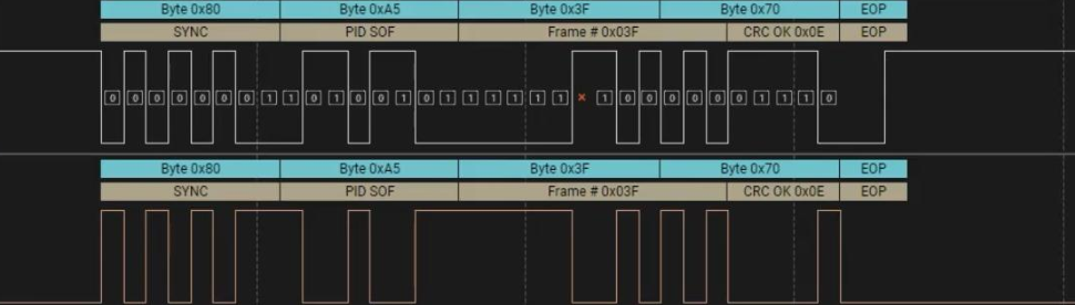
In the figure above, it is a start-of-frame packet. The SYNC field starts with 0x80 (10000000) to indicate clock synchronization. The PID field value is 0xA5, marked as SOF in the figure, indicating that this is a start-of-frame packet.

On the left is a token packet. The SYNC field starts with 0x80 (10000000) to indicate clock synchronization. The PID field value is 0x69, marked as IN in the figure, indicating that the device is notified to send data. Next, the host requests data from endpoint 2.
In the figure above, on the right is a handshake packet. The SYNC field starts with 0x80 (10000000) to indicate clock synchronization. The PID field value is 0x5A, marked as NAK in the figure, indicating that the device is temporarily unable to respond.

This waveform is a control transfer request in the enumeration phase. The SYNC field starts with 0x80 (10000000) to indicate clock synchronization. The PID field is SETUP, indicating that the device is notified that a control transfer is about to begin. Next are the address field Address=0x11 and the endpoint field Endpoint=0x00, indicating that the host sends a control request to endpoint 0. Finally, there is the CRC field, and the packet ends with EOP.
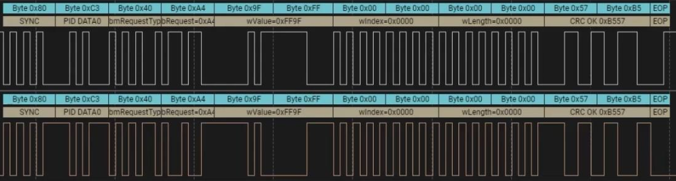
The SYNC field starts with 0x80 (10000000) to indicate clock synchronization. The PID field is DATA0, indicating that it is used for the data stage of a control transfer.
Application Programming Basics
Introduction to the libusb Library
libusb is a library written in C that provides a general-purpose access method for USB devices. Through it, applications can easily access USB devices without writing USB device drivers. The libusb library has three characteristics:
- Good portability, supporting Linux, macOS, and Windows systems.
- Simple and easy to use; applications do not need privileged mode or to elevate their permissions to access USB devices.
- Supports all USB protocols from USB 1.0 to USB 3.1, and the API interface remains unchanged, making development convenient.
Compiling libusb
Source code:

Local compilation
123456 | sudo apt install autoconf automake libtool libudev-dev m4./bootstrap.sh./autogen.shmake -j$(nproc)make install |
In the examples directory of the libusb source code, libusb provides some official examples, as shown below:
123456 | $ ls examplesdpfp ezusb.c fxload.o listdevs.c sam3u_benchmark testlibusb.odpfp.c ezusb.h hotplugtest listdevs.o sam3u_benchmark.c xusbdpfp.o ezusb.o hotplugtest.c Makefile sam3u_benchmark.o xusb.cdpfp_threaded fxload hotplugtest.o Makefile.am testlibusb xusb.odpfp_threaded-dpfp.o fxload.c listdevs Makefile.in testlibusb.c |
hotplugtest.cUsed to monitor the insertion and removal of USB devices in the system.listdevs.cGet and display the current USB device information of the system, including: VID, PID, bus number, device address, port number.testlibusb.cUsed to print detailed information of the USB device list: including device descriptors, configurations, interfaces, endpoint descriptors.
Cross compilation
123456789101112 | make distclean./autogen.shmkdir _install # Create installation directory# Add $HOME/tools/gcc-arm-11.2-2022.02-x86_64-aarch64-none-linux-gnu/bin to the environment variable./configure --host=aarch64-none-linux-gnu --disable-udev --prefix=$PWD/_install CC=aarch64-none-linux-gnu-gcc CXX=aarch64-none-linux-gnu-g++make -j$(nproc)make installls _install |
Compile examples
123456 | make -C examples \ CC=aarch64-none-linux-gnu-gcc \ CXX=aarch64-none-linux-gnu-g++ \ LDFLAGS="-L$(pwd)/_install/lib -pthread -static" \ CFLAGS="-I$(pwd)/_install/include/libusb-1.0" \ CPPFLAGS="-I$(pwd)/_install/include/libusb-1.0" |
libusb API
libusb_init()
| Item | Description |
|---|---|
| Function prototype | int libusb_init(libusb_context **ctx); |
| Parameters | libusb_context **ctx: context pointer, can be NULL to use the default context |
| Return value | Returns 0 on success; returns a negative error code on failure. |
| Function description | Initialize the libusb library; must be called before other libusb operations. |
libusb_get_device_list()
| Item | Description |
|---|---|
| Function prototype | ssize_t libusb_get_device_list(libusb_context *ctx, libusb_device ***list); |
| Parameters | ctx: contextlist: output device array |
| Return value | Returns the number of devices on success; returns a negative number on failure. |
| Function description | Get the list of currently connected USB devices. |
libusb_free_device_list()
| Item | Description |
|---|---|
| Function prototype | void libusb_free_device_list(libusb_device **list, int unref_devices); |
| Parameters | list: device listunref_devices: whether to decrease the reference count |
| Return value | None |
| Function description | Release device list |
libusb_open_device_with_vid_pid()
| Item | Description |
|---|---|
| Function prototype | libusb_device_handle *libusb_open_device_with_vid_pid(libusb_context *ctx, uint16_t vid, uint16_t pid); |
| Parameters | ctx: contextvid: vendor IDpid: product ID |
| Return value | Returns the device handle on success; returns NULL on failure. |
| Function description | Find and open device by VID/PID |
libusb_open()
| Item | Description |
|---|---|
| Function prototype | int libusb_open(libusb_device *dev, libusb_device_handle **dev_handle); |
| Parameters | dev: device pointerdev_handle: output device handle |
| Return value | Returns 0 on success; returns a negative number on failure |
| Function description | Open the specified USB device |
libusb_get_device_descriptor()
| Item | Description |
|---|---|
| Function prototype | int libusb_get_device_descriptor(libusb_device *dev, struct libusb_device_descriptor *desc); |
| Parameters | dev: devicedesc: output device descriptor |
| Return value | Returns 0 on success; Returns a negative number on failure |
| Function description | Get device descriptor |
libusb_get_config_descriptor()
| Item | Description |
|---|---|
| Function prototype | int libusb_get_config_descriptor(libusb_device *dev, uint8_t config_index, struct libusb_config_descriptor **config); |
| Parameters | dev: deviceconfig_index: configuration indexconfig: output configuration descriptor |
| Return value | Returns 0 on success; Returns a negative number on failure |
| Function description | Get device configuration descriptor |
libusb_free_config_descriptor()
| Item | Description |
|---|---|
| Function prototype | void libusb_free_config_descriptor(struct libusb_config_descriptor *config); |
| Parameters | config: configuration descriptor |
| Return value | None |
| Function description | Release configuration descriptor |
libusb_bulk_transfer()
| Item | Description |
|---|---|
| Function prototype | int libusb_bulk_transfer(libusb_device_handle *dev_handle, unsigned char endpoint, unsigned char *data, int length, int *actual_length, unsigned int timeout); |
| Parameters | dev_handle: Device handleendpoint: endpoint addressdata: Bufferlength: Lengthactual_length: Actual lengthtimeout: Timeout (ms) |
| Return value | Returns 0 on success; Returns a negative number on failure |
| Function description | Perform USB bulk transfer |
libusb_interrupt_transfer()
| Item | Description |
|---|---|
| Function prototype | int libusb_interrupt_transfer(libusb_device_handle *dev_handle, unsigned char endpoint, unsigned char *data, int length, int *actual_length, unsigned int timeout); |
| Parameters | dev_handle: Device handleendpoint: endpoint addressdata: Bufferlength: Lengthactual_length: Actual lengthtimeout: Timeout (ms) |
| Return value | Returns 0 on success; Returns a negative number on failure |
| Function description | Perform USB interrupt transfer |
libusb_set_auto_detach_kernel_driver()
| Item | Description |
|---|---|
| Function prototype | int libusb_set_auto_detach_kernel_driver(libusb_device_handle *dev_handle, int enable); |
| Parameters | dev_handle: Device handleenable: 1 enable / 0 disable |
| Return value | Returns 0 on success; Returns a negative number on failure |
| Function description | Automatically detach kernel driver |
libusb_claim_interface()
| Item | Description |
|---|---|
| Function prototype | int libusb_claim_interface(libusb_device_handle *dev_handle, int interface_number); |
| Parameters | dev_handle: Device handleinterface_number: Interface number |
| Return value | Returns 0 on success; Returns a negative number on failure |
| Function description | Declare device interface |
libusb_alloc_transfer()
| Item | Description |
|---|---|
| Function prototype | struct libusb_transfer *libusb_alloc_transfer(int iso_packets); |
| Parameters | iso_packets: Number of isochronous transfer packets |
| Return value | Returns the transfer pointer on success; Returns NULL on failure |
| Function description | Allocate asynchronous transfer structure |
libusb_fill_interrupt_transfer()
| Item | Description |
|---|---|
| Function prototype | void libusb_fill_interrupt_transfer(struct libusb_transfer *transfer, libusb_device_handle *dev_handle,unsigned char endpoint, unsigned char *buffer, int length,libusb_transfer_cb_fn callback, void *user_data, unsigned int timeout) |
| Parameters | transfer: Transfer objectdev_handle: Device handleendpoint: Endpointbuffer: Bufferlength: Lengthcallback: Callback functionuser_data: User datatimeout: Timeout |
| Return value | None |
| Function description | Configure asynchronous interrupt transfer object |
libusb_submit_transfer()
| Item | Description |
|---|---|
| Function prototype | int libusb_submit_transfer(struct libusb_transfer *transfer); |
| Parameters | transfer: Configured transfer object |
| Return value | Returns 0 on success; Returns a negative number on failure |
| Function description | Submit asynchronous transfer |
libusb_cancel_transfer()
| Item | Description |
|---|---|
| Function prototype | int libusb_cancel_transfer(struct libusb_transfer *transfer); |
| Parameters | transfer: Transfer object |
| Return value | Returns 0 on success; Returns a negative number on failure |
| Function description | Cancel asynchronous transfer |
libusb_free_transfer()
| Item | Description |
|---|---|
| Function prototype | void libusb_free_transfer(struct libusb_transfer *transfer); |
| Parameters | transfer: Transfer object |
| Return value | None |
| Function description | Release transfer structure |
libusb_handle_events()
| Item | Description |
|---|---|
| Function prototype | int libusb_handle_events(libusb_context *ctx); |
| Parameters | ctx: context |
| Return value | Returns 0 on success; Returns a negative number on failure |
| Function description | Process pending events (blocking mode) |
example
Example 1
123456789101112131415161718192021222324252627282930313233343536373839404142434445464748 | int main(void){ int ret; // Function return value storage int cnt; // Device count libusb_device **device = NULL; // Device list pointer libusb_device *dev; // Single device pointer int i = 0; // Loop counter // Initialize libusb library ret = libusb_init(NULL); if (ret < 0) { printf("libusb_init error \n"); return ret; } // Get USB device list cnt = libusb_get_device_list(NULL, &device); if (cnt < 0) { printf("libusb_get_device_list error \n"); return cnt; } // Iterate through device list while (dev = device[i++]) { struct libusb_device_descriptor desc; // Device descriptor // Get device descriptor ret = libusb_get_device_descriptor(dev, &desc); if (ret < 0) { printf("libusb_get_device_descriptor error \n"); return ret; } // Print vendor ID and product ID printf("%04x : %04x\n", desc.idVendor, desc.idProduct); } // Release device list (unref=1 means decrement reference count) libusb_free_device_list(device, 1); // Release all resources occupied by the libusb library libusb_exit(NULL); return 0;} |
Example 2
123456789101112131415161718192021222324252627282930313233343536373839404142434445464748495051525354555657585960616263646566676869707172737475767778798081828384858687888990919293949596979899100101102 | int main(void){ // Variable declaration area int ret; // Store function return value int cnt; // Device counter libusb_device **device = NULL; // USB device list pointer libusb_device *dev; // Single USB device pointer int i = 0, k = 0, j = 0; // Loop counter int endpoint; // Endpoint address int flag = 0; // Flags // Descriptor struct struct libusb_config_descriptor *config_desc = NULL; // USB configuration descriptor const struct libusb_interface_descriptor *interface_descriptor = NULL; // Interface descriptor. libusb_device_handle *dev_handle = NULL; // USB device handle // Data buffer unsigned char buffer[16]; // Data receive buffer int transferred; // Actual number of bytes transferred // Initialize libusb library ret = libusb_init(NULL); if (ret < 0) { printf("libusb初始化失败\n"); return ret; } // Get USB device list cnt = libusb_get_device_list(NULL, &device); if (cnt < 0) { printf("获取设备列表失败\n"); return cnt; } // Traverse device list to find HID device while (dev = device[i++]) { // Get device configuration descriptor ret = libusb_get_config_descriptor(dev, 0, &config_desc); if (ret < 0) { printf("获取配置描述符失败\n"); return ret; } // Traverse all interfaces for (k = 0; k < config_desc->bNumInterfaces; k++) { interface_descriptor = &config_desc->interface[k].altsetting[0]; // Find HID class device (Class=3) and keyboard protocol (Protocol=1) if (interface_descriptor->bInterfaceClass == 3 && interface_descriptor->bInterfaceProtocol == 1) { // Traverse endpoints to find interrupt input endpoint for (j = 0; j < interface_descriptor->bNumEndpoints; j++) { if ((interface_descriptor->endpoint[j].bmAttributes & 3) == LIBUSB_TRANSFER_TYPE_INTERRUPT || (interface_descriptor->endpoint[j].bmAttributes & 0x80) == LIBUSB_ENDPOINT_IN) { endpoint = interface_descriptor->endpoint[j].bEndpointAddress; flag = 1; // Found target device break; } } } if (flag) break; } if (flag) break; } // Open target device ret = libusb_open(dev, &dev_handle); if (ret < 0) { printf("打开设备失败\n"); return ret; } // Set auto-unload kernel driver libusb_set_auto_detach_kernel_driver(dev_handle, 1); // Declare interface libusb_claim_interface(dev_handle, interface_descriptor->bInterfaceNumber); // Main loop: continuously read keyboard data while (1) { // Read keyboard data using interrupt transfer ret = libusb_interrupt_transfer(dev_handle, endpoint, buffer, 16, &transferred, 5000); if (ret >= 0) { // Read successful // Print received keyboard data for (i = 0; i < transferred; i++) { printf("%02x ", buffer[i]); } printf("\n"); } } // Resource release libusb_free_config_descriptor(config_desc); // Release configuration descriptor libusb_free_device_list(device, 1); // Release device list libusb_exit(NULL); // Release libusb resources return 0;} |
Example 3
123456789101112131415161718192021222324252627282930313233343536373839404142434445464748495051525354555657585960616263646566676869707172737475767778798081828384858687888990919293949596979899100101102103104105106107108109110111112113114115116117118119120121122123124125126127128 | // Global variable declarationstruct libusb_transfer *keyboard_transfer = NULL; // Asynchronous transfer control blockunsigned char buffer[16]; // Keyboard data receive bufferint ret; // Function return value storage// Asynchronous transfer callback functionvoid callback_recv(struct libusb_transfer *transfer) { int k; if (keyboard_transfer->status == LIBUSB_TRANSFER_COMPLETED) { if (transfer->actual_length > 0) { // Print received keyboard data (hex) for (k = 0; k < transfer->actual_length; k++) { printf("%02x ", buffer[k]); } printf("\n"); } } // Resubmit transfer request (to achieve continuous listening) ret = libusb_submit_transfer(keyboard_transfer); if (ret < 0) { libusb_cancel_transfer(keyboard_transfer); libusb_free_transfer(keyboard_transfer); }}int main(void) { // Device enumeration variables int cnt; // Device count counter libusb_device **device = NULL; // USB device list libusb_device *dev = NULL; // Current device pointer int i = 0, k = 0, j = 0; // Loop counter int endpoint; // Endpoint address int flag = 0; // Device lookup flag // USB descriptor pointer struct libusb_config_descriptor *config_desc = NULL; // Configuration Descriptor const struct libusb_interface_descriptor *interface_descriptor = NULL; // Interface descriptor. libusb_device_handle *dev_handle = NULL; // Device operation handle // Initialize libusb library ret = libusb_init(NULL); if (ret < 0) { printf("libusb初始化失败\n"); return ret; } // Get USB device list cnt = libusb_get_device_list(NULL, &device); if (cnt < 0) { printf("获取设备列表失败\n"); return cnt; } // Traverse devices to find HID keyboard while ((dev = device[i++])) { // Get default configuration descriptor ret = libusb_get_config_descriptor(dev, 0, &config_desc); if (ret < 0) { printf("获取配置描述符失败\n"); return ret; } // Traverse all interfaces for (k = 0; k < config_desc->bNumInterfaces; k++) { interface_descriptor = &config_desc->interface[k].altsetting[0]; // Check if it is a HID keyboard device (Class=3, Protocol=1) if (interface_descriptor->bInterfaceClass == 3 && interface_descriptor->bInterfaceProtocol == 1) { // Find interrupt input endpoint for (j = 0; j < interface_descriptor->bNumEndpoints; j++) { if ((interface_descriptor->endpoint[j].bmAttributes & 3) == LIBUSB_TRANSFER_TYPE_INTERRUPT || (interface_descriptor->endpoint[j].bmAttributes & 0x80) == LIBUSB_ENDPOINT_IN) { endpoint = interface_descriptor->endpoint[j].bEndpointAddress; flag = 1; // Mark target device as found break; } } } if (flag) break; } if (flag) break; } // Open the found keyboard device ret = libusb_open(dev, &dev_handle); if (ret < 0) { printf("打开设备失败\n"); return ret; } // Set auto-detach kernel driver (to avoid conflict) libusb_set_auto_detach_kernel_driver(dev_handle, 1); // Claim the interface libusb_claim_interface(dev_handle, interface_descriptor->bInterfaceNumber); // Configure asynchronous transfer keyboard_transfer = libusb_alloc_transfer(0); // Allocate transfer control block libusb_fill_interrupt_transfer( // Fill interrupt transfer parameters keyboard_transfer, dev_handle, endpoint, buffer, 16, callback_recv, NULL, 5000); // Submit asynchronous transfer request ret = libusb_submit_transfer(keyboard_transfer); if (ret < 0) { libusb_cancel_transfer(keyboard_transfer); libusb_free_transfer(keyboard_transfer); return ret; } // Main event loop (handle USB events) while (1) { libusb_handle_events(NULL); } // Resource cleanup (not actually reached here) libusb_free_config_descriptor(config_desc); libusb_free_device_list(device, 1); libusb_exit(NULL); return 0;} |
USB driver development framework
In the Linux kernel, USB driver development is mainly divided into two categories:
- Host-side driver
- and device-side driver.
The host-side driver is responsible for managing USB devices plugged into the host; the device-side driver is responsible for the way the device communicates with the host as a USB device.
Since the term “USB devices drivers” is prone to confusion, people usually use “usb gadget driver” to describe USB device drivers.
At the hardware level, the USB controllers on the host side and device side are called the Host Controller and USB Device Controller (UDC), respectively, as shown in the figure below.
12345678910111213141516 | ┌─────────────────────┐ ┌─────────────────────┐│ USB设备驱动 │ │ Gadget Function驱动 │└───────────┬─────────┘ └───────────┬─────────┘ │ │┌───────────▼─────────┐ ┌───────────▼─────────┐│ USB核心层 │ │ Gadget Function API │└───────────┬─────────┘ └───────────┬─────────┘ │ │┌───────────▼─────────┐ ┌───────────▼─────────┐│ USB主机控制器驱动 │ │ UDC驱动 │└───────────┬─────────┘ └───────────┬─────────┘ └──────────────┬──────────────┘ │ ┌────────▼────────┐ │ USB总线 │ └─────────────────┘ |
In Linux, USB drivers can be viewed from both the host side and the device side. From the host side, the USB host controller driver is at the bottom of the USB driver stack and is responsible for controlling the hardware. Above it runs the USB core layer, and above that is the USB device driver.
From the device side, the USB device-side driver has three layers: the UDC driver, the Gadget Function API, and the Gadget Function driver.
The USB driver architecture is shown in the figure below.

The Linux USB protocol stack is a layered architecture. On the left are USB Device drivers, on the right are USB Host drivers, the top layer is the application layer, the bottom layer consists of drivers for the different USB controllers and PHYs of Rockchip series chips, and in the middle is the USB core layer.
USB keyboard driver example
Let the iTOP-RK3568 development board act as a USB host, connecting external USB devices such as a USB keyboard.
In Rockchip’s official kernel source, the USB keyboard and mouse drivers are enabled by default. To proceed with subsequent USB keyboard driver development experiments, you need to disable this default driver setting. Since USB mice and keyboards are HID devices, we can open the kernel configuration interface by entering the following command to enable or disable the HID driver.
123456 | ---> Device Drivers ---> HID support ---> USB HID support <*> USB HID transport layer [ ] PID device support [*] /dev/hiddev raw HID device support |
Disable the USB HID transport layer.
Its help information is as follows:
1234567891011121314151617181920 | CONFIG_USB_HID:Say Y here if you want to connect USB keyboards, mice, joysticks, graphic tablets, or any other HID based devices to your computer via USB, as well as Uninterruptible Power Supply (UPS) and monitor control devices.You can't use this driver and the HIDBP (Boot Protocol) keyboard and mouse drivers at the same time. More information is available: file:Documentation/input/input.rst.If unsure, say Y.To compile this driver as a module, choose M here: the module will be called usbhid.Symbol: USB_HID [=y]Type : tristateDefined at drivers/hid/usbhid/Kconfig:5 Prompt: USB HID transport layer Depends on: USB [=y] && INPUT [=y] Location: -> Device Drivers -> HID support -> USB HID supportSelects: HID [=y] |
struct usb_driver *driver
is the driver description structure, whose core members are defined as follows:
12345678910111213141516171819202122232425262728293031323334353637383940414243444546474849505152535455565758596061626364656667686970717273747576777879808182838485868788899091929394 | /** * struct usb_driver - identifies USB interface driver to usbcore * @name: The driver name should be unique among USB drivers, * and should normally be the same as the module name. * @probe: Called to see if the driver is willing to manage a particular * interface on a device. If it is, probe returns zero and uses * usb_set_intfdata() to associate driver-specific data with the * interface. It may also use usb_set_interface() to specify the * appropriate altsetting. If unwilling to manage the interface, * return -ENODEV, if genuine IO errors occurred, an appropriate * negative errno value. * @disconnect: Called when the interface is no longer accessible, usually * because its device has been (or is being) disconnected or the * driver module is being unloaded. * @unlocked_ioctl: Used for drivers that want to talk to userspace through * the "usbfs" filesystem. This lets devices provide ways to * expose information to user space regardless of where they * do (or don't) show up otherwise in the filesystem. * @suspend: Called when the device is going to be suspended by the * system either from system sleep or runtime suspend context. The * return value will be ignored in system sleep context, so do NOT * try to continue using the device if suspend fails in this case. * Instead, let the resume or reset-resume routine recover from * the failure. * @resume: Called when the device is being resumed by the system. * @reset_resume: Called when the suspended device has been reset instead * of being resumed. * @pre_reset: Called by usb_reset_device() when the device is about to be * reset. This routine must not return until the driver has no active * URBs for the device, and no more URBs may be submitted until the * post_reset method is called. * @post_reset: Called by usb_reset_device() after the device * has been reset * @id_table: USB drivers use ID table to support hotplugging. * Export this with MODULE_DEVICE_TABLE(usb,...). This must be set * or your driver's probe function will never get called. * @dev_groups: Attributes attached to the device that will be created once it * is bound to the driver. * @dynids: used internally to hold the list of dynamically added device * ids for this driver. * @drvwrap: Driver-model core structure wrapper. * @no_dynamic_id: if set to 1, the USB core will not allow dynamic ids to be * added to this driver by preventing the sysfs file from being created. * @supports_autosuspend: if set to 0, the USB core will not allow autosuspend * for interfaces bound to this driver. * @soft_unbind: if set to 1, the USB core will not kill URBs and disable * endpoints before calling the driver's disconnect method. * @disable_hub_initiated_lpm: if set to 1, the USB core will not allow hubs * to initiate lower power link state transitions when an idle timeout * occurs. Device-initiated USB 3.0 link PM will still be allowed. * * USB interface drivers must provide a name, probe() and disconnect() * methods, and an id_table. Other driver fields are optional. * * The id_table is used in hotplugging. It holds a set of descriptors, * and specialized data may be associated with each entry. That table * is used by both user and kernel mode hotplugging support. * * The probe() and disconnect() methods are called in a context where * they can sleep, but they should avoid abusing the privilege. Most * work to connect to a device should be done when the device is opened, * and undone at the last close. The disconnect code needs to address * concurrency issues with respect to open() and close() methods, as * well as forcing all pending I/O requests to complete (by unlinking * them as necessary, and blocking until the unlinks complete). */struct usb_driver { const char *name;// Driver name int (*probe) (struct usb_interface *intf, const struct usb_device_id *id); // When a matching USB device is detected, the kernel calls this function. void (*disconnect) (struct usb_interface *intf); // Called when the device is disconnected or the driver is unloaded. int (*unlocked_ioctl) (struct usb_interface *intf, unsigned int code, void *buf); int (*suspend) (struct usb_interface *intf, pm_message_t message); int (*resume) (struct usb_interface *intf); int (*reset_resume)(struct usb_interface *intf); int (*pre_reset)(struct usb_interface *intf); int (*post_reset)(struct usb_interface *intf); const struct usb_device_id *id_table; // Pointer to usb_device_id structure array, defining the list of devices supported by the driver. const struct attribute_group **dev_groups; struct usb_dynids dynids; struct usbdrv_wrap drvwrap; unsigned int no_dynamic_id:1; unsigned int supports_autosuspend:1; unsigned int disable_hub_initiated_lpm:1; unsigned int soft_unbind:1;}; |
struct usb_device_id
In the main structure of the driverusb_driverthrough.id_tablefield binds the device table to the driver
1234567891011121314151617181920212223242526272829303132333435363738394041424344454647484950515253545556575859606162636465666768697071727374 | /** * struct usb_device_id - identifies USB devices for probing and hotplugging * @match_flags: Bit mask controlling which of the other fields are used to * match against new devices. Any field except for driver_info may be * used, although some only make sense in conjunction with other fields. * This is usually set by a USB_DEVICE_*() macro, which sets all * other fields in this structure except for driver_info. * @idVendor: USB vendor ID for a device; numbers are assigned * by the USB forum to its members. * @idProduct: Vendor-assigned product ID. * @bcdDevice_lo: Low end of range of vendor-assigned product version numbers. * This is also used to identify individual product versions, for * a range consisting of a single device. * @bcdDevice_hi: High end of version number range. The range of product * versions is inclusive. * @bDeviceClass: Class of device; numbers are assigned * by the USB forum. Products may choose to implement classes, * or be vendor-specific. Device classes specify behavior of all * the interfaces on a device. * @bDeviceSubClass: Subclass of device; associated with bDeviceClass. * @bDeviceProtocol: Protocol of device; associated with bDeviceClass. * @bInterfaceClass: Class of interface; numbers are assigned * by the USB forum. Products may choose to implement classes, * or be vendor-specific. Interface classes specify behavior only * of a given interface; other interfaces may support other classes. * @bInterfaceSubClass: Subclass of interface; associated with bInterfaceClass. * @bInterfaceProtocol: Protocol of interface; associated with bInterfaceClass. * @bInterfaceNumber: Number of interface; composite devices may use * fixed interface numbers to differentiate between vendor-specific * interfaces. * @driver_info: Holds information used by the driver. Usually it holds * a pointer to a descriptor understood by the driver, or perhaps * device flags. * * In most cases, drivers will create a table of device IDs by using * USB_DEVICE(), or similar macros designed for that purpose. * They will then export it to userspace using MODULE_DEVICE_TABLE(), * and provide it to the USB core through their usb_driver structure. * * See the usb_match_id() function for information about how matches are * performed. Briefly, you will normally use one of several macros to help * construct these entries. Each entry you provide will either identify * one or more specific products, or will identify a class of products * which have agreed to behave the same. You should put the more specific * matches towards the beginning of your table, so that driver_info can * record quirks of specific products. */struct usb_device_id { /* which fields to match against? */ __u16 match_flags; // Match flags (specify which fields participate in matching /* Used for product specific matches; range is inclusive */ __u16 idVendor; // Vendor ID (VID) __u16 idProduct; // Product ID (PID) __u16 bcdDevice_lo; // Device version lower limit __u16 bcdDevice_hi; // Device version upper limit /* Used for device class matches */ __u8 bDeviceClass; // Device class __u8 bDeviceSubClass; // Device subclass __u8 bDeviceProtocol; // Device protocol /* Used for interface class matches */ __u8 bInterfaceClass; // Interface class __u8 bInterfaceSubClass; // Interface subclass __u8 bInterfaceProtocol; // Interface protocol /* Used for vendor-specific interface matches */ __u8 bInterfaceNumber; /* not matched against */ kernel_ulong_t driver_info __attribute__((aligned(sizeof(kernel_ulong_t)))); // Driver private data (optional)}; |
usb_register()
| Item | Description |
|---|---|
| Function prototype | int usb_register(struct usb_driver *driver); |
| Header file | #include <linux/usb.h> |
| Parameters | struct usb_driver *driver: USB driver description structure pointer |
| Return value | Returns 0 on success; Returns a negative error code on failure |
| Function description | Register the USB driver with the Linux USB subsystem, enabling the driver to respond to plug/unplug events of matching devices. |
Beforeusb_registerIn the function, its underlying callusb_register_driver, the driver structureusb_driverregisters with the kernel USB subsystem. Callingusb_register_driverafter, theusb_driverstructure is mounted to the USB bus (usb_bus_type) in the driver list, as shown below:
123 | /* use a define to avoid include chaining to get THIS_MODULE & friends */ |
usb_register_driver()
123456789101112131415161718192021222324252627282930313233343536373839404142434445464748495051525354555657 | /** * usb_register_driver - register a USB interface driver * @new_driver: USB operations for the interface driver * @owner: module owner of this driver. * @mod_name: module name string * * Registers a USB interface driver with the USB core. The list of * unattached interfaces will be rescanned whenever a new driver is * added, allowing the new driver to attach to any recognized interfaces. * * Return: A negative error code on failure and 0 on success. * * NOTE: if you want your driver to use the USB major number, you must call * usb_register_dev() to enable that functionality. This function no longer * takes care of that. */int usb_register_driver(struct usb_driver *new_driver, struct module *owner, const char *mod_name){ int retval = 0; if (usb_disabled()) return -ENODEV; new_driver->drvwrap.for_devices = 0; new_driver->drvwrap.driver.name = new_driver->name; new_driver->drvwrap.driver.bus = &usb_bus_type; new_driver->drvwrap.driver.probe = usb_probe_interface; new_driver->drvwrap.driver.remove = usb_unbind_interface; new_driver->drvwrap.driver.owner = owner; new_driver->drvwrap.driver.mod_name = mod_name; new_driver->drvwrap.driver.dev_groups = new_driver->dev_groups; spin_lock_init(&new_driver->dynids.lock); INIT_LIST_HEAD(&new_driver->dynids.list); retval = driver_register(&new_driver->drvwrap.driver); if (retval) goto out; retval = usb_create_newid_files(new_driver); if (retval) goto out_newid; pr_info("%s: registered new interface driver %s\n", usbcore_name, new_driver->name);out: return retval;out_newid: driver_unregister(&new_driver->drvwrap.driver); pr_err("%s: error %d registering interface driver %s\n", usbcore_name, retval, new_driver->name); goto out;}EXPORT_SYMBOL_GPL(usb_register_driver); |
usb_bus_typeThe structure has a match member,usb_device_matchThe function is responsible for the matching logic.
123456 | struct bus_type usb_bus_type = { .name = "usb", .match = usb_device_match, .uevent = usb_uevent, .need_parent_lock = true,}; |
usb_device_match()
12345678910111213141516171819202122232425262728293031323334353637383940414243444546474849 | static int usb_device_match(struct device *dev, struct device_driver *drv){ /* devices and interfaces are handled separately */ if (is_usb_device(dev)) { // Determine whether it is a USB device object. struct usb_device *udev; struct usb_device_driver *udrv; /* interface drivers never match devices */ if (!is_usb_device_driver(drv)) // Check whether the driver is a device-level driver. return 0; udev = to_usb_device(dev); udrv = to_usb_device_driver(drv); /* If the device driver under consideration does not have a * id_table or a match function, then let the driver's probe * function decide. */ if (!udrv->id_table && !udrv->match) return 1; return usb_driver_applicable(udev, udrv); } else if (is_usb_interface(dev)) { // Determine whether it is a USB interface object. struct usb_interface *intf; struct usb_driver *usb_drv; const struct usb_device_id *id; /* device drivers never match interfaces */ /* Device driver does not match interface: prevent the device driver from being incorrectly bound to the interface. */ if (is_usb_device_driver(drv)) return 0; intf = to_usb_interface(dev); // Get the interface instance. usb_drv = to_usb_driver(drv); // Get the USB driver instance. /* Match static device ID table (id_table defined at driver registration) */ id = usb_match_id(intf, usb_drv->id_table); if (id) return 1; /* Match dynamic IDs (e.g., temporary device IDs added via sysfs) */ id = usb_match_dynamic_id(intf, usb_drv); if (id) return 1; } return 0;} |
Used in the above functionusb_match_idThe function matches the static device ID table,usb_match_idThe function implementation is as follows:
usb_match_id()
123456789101112131415161718192021222324252627282930313233343536373839404142434445464748495051525354555657585960616263646566676869707172737475767778798081828384858687888990919293949596979899100 | /** * usb_match_id - find first usb_device_id matching device or interface * @interface: the interface of interest * @id: array of usb_device_id structures, terminated by zero entry * * usb_match_id searches an array of usb_device_id's and returns * the first one matching the device or interface, or null. * This is used when binding (or rebinding) a driver to an interface. * Most USB device drivers will use this indirectly, through the usb core, * but some layered driver frameworks use it directly. * These device tables are exported with MODULE_DEVICE_TABLE, through * modutils, to support the driver loading functionality of USB hotplugging. * * Return: The first matching usb_device_id, or %NULL. * * What Matches: * * The "match_flags" element in a usb_device_id controls which * members are used. If the corresponding bit is set, the * value in the device_id must match its corresponding member * in the device or interface descriptor, or else the device_id * does not match. * * "driver_info" is normally used only by device drivers, * but you can create a wildcard "matches anything" usb_device_id * as a driver's "modules.usbmap" entry if you provide an id with * only a nonzero "driver_info" field. If you do this, the USB device * driver's probe() routine should use additional intelligence to * decide whether to bind to the specified interface. * * What Makes Good usb_device_id Tables: * * The match algorithm is very simple, so that intelligence in * driver selection must come from smart driver id records. * Unless you have good reasons to use another selection policy, * provide match elements only in related groups, and order match * specifiers from specific to general. Use the macros provided * for that purpose if you can. * * The most specific match specifiers use device descriptor * data. These are commonly used with product-specific matches; * the USB_DEVICE macro lets you provide vendor and product IDs, * and you can also match against ranges of product revisions. * These are widely used for devices with application or vendor * specific bDeviceClass values. * * Matches based on device class/subclass/protocol specifications * are slightly more general; use the USB_DEVICE_INFO macro, or * its siblings. These are used with single-function devices * where bDeviceClass doesn't specify that each interface has * its own class. * * Matches based on interface class/subclass/protocol are the * most general; they let drivers bind to any interface on a * multiple-function device. Use the USB_INTERFACE_INFO * macro, or its siblings, to match class-per-interface style * devices (as recorded in bInterfaceClass). * * Note that an entry created by USB_INTERFACE_INFO won't match * any interface if the device class is set to Vendor-Specific. * This is deliberate; according to the USB spec the meanings of * the interface class/subclass/protocol for these devices are also * vendor-specific, and hence matching against a standard product * class wouldn't work anyway. If you really want to use an * interface-based match for such a device, create a match record * that also specifies the vendor ID. (Unforunately there isn't a * standard macro for creating records like this.) * * Within those groups, remember that not all combinations are * meaningful. For example, don't give a product version range * without vendor and product IDs; or specify a protocol without * its associated class and subclass. */const struct usb_device_id *usb_match_id(struct usb_interface *interface, const struct usb_device_id *id){ /* proc_connectinfo in devio.c may call us with id == NULL. */ /* Handle special case: return directly when the id table is empty */ if (id == NULL) return NULL; /* It is important to check that id->driver_info is nonzero, since an entry that is all zeroes except for a nonzero id->driver_info is the way to create an entry that indicates that the driver want to examine every device and interface. */ /* * Traverse the device ID table ID Table,until an all-zero terminator entry is encountered: * Loop condition check id field is not all zeros */ for (; id->idVendor || id->idProduct || id->bDeviceClass || id->bInterfaceClass || id->driver_info; id++) { /* Call the core match function to check whether the current id matches the interface */ if (usb_match_one_id(interface, id)) return id; // If match succeeds, return the entry } return NULL; // No match found after traversing all entries}EXPORT_SYMBOL_GPL(usb_match_id); |
In the above code,usb_match_one_idthe function is used to determine whether a USB interface matchesusb_device_idmatches, and the function implementation is as follows:
usb_match_one_id()
123456789101112131415161718192021222324 | /* returns 0 if no match, 1 if match */int usb_match_one_id(struct usb_interface *interface, const struct usb_device_id *id){ struct usb_host_interface *intf; struct usb_device *dev; /* proc_connectinfo in devio.c may call us with id == NULL. */ // 1. Null pointer protection: if id is NULL, return no match directly if (id == NULL) return 0; // 2. Get the current interface's setting (cur_altsetting) and the associated USB device intf = interface->cur_altsetting; dev = interface_to_usbdev(interface); // 3. Device-level matching: check the device descriptor (VID/PID/device class, etc.) if (!usb_match_device(dev, id)) return 0; // 4. Interface-level matching: check the interface descriptor (interface class/subclass/protocol, etc.) return usb_match_one_id_intf(dev, intf, id);}EXPORT_SYMBOL_GPL(usb_match_one_id); |
According tousb_device_idinmatch_flagsfield, which determines the fields to match (e.g., VID, PID, interface class, etc.), an example match table is shown below
12345 | // Define the device match tablestatic const struct usb_device_id my_kbd_id_table[] = { {USB_INTERFACE_INFO(USB_INTERFACE_CLASS_HID, USB_INTERFACE_SUBCLASS_BOOT, USB_INTERFACE_PROTOCOL_KEYBOARD)}, {}, // Terminator (must keep an empty entry) }; |
usb_deregister()
| Item | Description |
|---|---|
| Function prototype | void usb_deregister(struct usb_driver *driver); |
| Header file | #include <linux/usb.h> |
| Parameters | struct usb_driver *driver: registered USB driver |
| Return value | None |
| Function description | Unregister the driver from the USB subsystem and trigger the disconnect() callback for all matching devices. |
USB Request Block
URB, i.e., USB Request Block, is called USB request block in Chinese. In USB device drivers, it is the basic carrier and core data structure used to describe communication with USB devices, and is similar to the one in network device drivers.sk_buffThe structure is extremely similar. The URB structure is as follows:
123456789101112131415161718192021222324252627282930313233343536373839404142434445464748495051525354555657585960616263646566676869707172737475767778798081828384858687888990919293949596979899100101102103104105106107108109110111112113114115116117118119120121122123124125126127128129130131132133134135136137138139140141142143144145146147148149150151152153154155156157158159160161162163164165166167168169170171172173174175176177178179180181182183184185186187188189190191192193194195196197198199200201202203204205206207208209210211212213214215216217218219220221222223 | /** * struct urb - USB Request Block * @urb_list: For use by current owner of the URB. * @anchor_list: membership in the list of an anchor * @anchor: to anchor URBs to a common mooring * @ep: Points to the endpoint's data structure. Will eventually * replace @pipe. * @pipe: Holds endpoint number, direction, type, and more. * Create these values with the eight macros available; * usb_{snd,rcv}TYPEpipe(dev,endpoint), where the TYPE is "ctrl" * (control), "bulk", "int" (interrupt), or "iso" (isochronous). * For example usb_sndbulkpipe() or usb_rcvintpipe(). Endpoint * numbers range from zero to fifteen. Note that "in" endpoint two * is a different endpoint (and pipe) from "out" endpoint two. * The current configuration controls the existence, type, and * maximum packet size of any given endpoint. * @stream_id: the endpoint's stream ID for bulk streams * @dev: Identifies the USB device to perform the request. * @status: This is read in non-iso completion functions to get the * status of the particular request. ISO requests only use it * to tell whether the URB was unlinked; detailed status for * each frame is in the fields of the iso_frame-desc. * @transfer_flags: A variety of flags may be used to affect how URB * submission, unlinking, or operation are handled. Different * kinds of URB can use different flags. * @transfer_buffer: This identifies the buffer to (or from) which the I/O * request will be performed unless URB_NO_TRANSFER_DMA_MAP is set * (however, do not leave garbage in transfer_buffer even then). * This buffer must be suitable for DMA; allocate it with * kmalloc() or equivalent. For transfers to "in" endpoints, contents * of this buffer will be modified. This buffer is used for the data * stage of control transfers. * @transfer_dma: When transfer_flags includes URB_NO_TRANSFER_DMA_MAP, * the device driver is saying that it provided this DMA address, * which the host controller driver should use in preference to the * transfer_buffer. * @sg: scatter gather buffer list, the buffer size of each element in * the list (except the last) must be divisible by the endpoint's * max packet size if no_sg_constraint isn't set in 'struct usb_bus' * @num_mapped_sgs: (internal) number of mapped sg entries * @num_sgs: number of entries in the sg list * @transfer_buffer_length: How big is transfer_buffer. The transfer may * be broken up into chunks according to the current maximum packet * size for the endpoint, which is a function of the configuration * and is encoded in the pipe. When the length is zero, neither * transfer_buffer nor transfer_dma is used. * @actual_length: This is read in non-iso completion functions, and * it tells how many bytes (out of transfer_buffer_length) were * transferred. It will normally be the same as requested, unless * either an error was reported or a short read was performed. * The URB_SHORT_NOT_OK transfer flag may be used to make such * short reads be reported as errors. * @setup_packet: Only used for control transfers, this points to eight bytes * of setup data. Control transfers always start by sending this data * to the device. Then transfer_buffer is read or written, if needed. * @setup_dma: DMA pointer for the setup packet. The caller must not use * this field; setup_packet must point to a valid buffer. * @start_frame: Returns the initial frame for isochronous transfers. * @number_of_packets: Lists the number of ISO transfer buffers. * @interval: Specifies the polling interval for interrupt or isochronous * transfers. The units are frames (milliseconds) for full and low * speed devices, and microframes (1/8 millisecond) for highspeed * and SuperSpeed devices. * @error_count: Returns the number of ISO transfers that reported errors. * @context: For use in completion functions. This normally points to * request-specific driver context. * @complete: Completion handler. This URB is passed as the parameter to the * completion function. The completion function may then do what * it likes with the URB, including resubmitting or freeing it. * @iso_frame_desc: Used to provide arrays of ISO transfer buffers and to * collect the transfer status for each buffer. * * This structure identifies USB transfer requests. URBs must be allocated by * calling usb_alloc_urb() and freed with a call to usb_free_urb(). * Initialization may be done using various usb_fill_*_urb() functions. URBs * are submitted using usb_submit_urb(), and pending requests may be canceled * using usb_unlink_urb() or usb_kill_urb(). * * Data Transfer Buffers: * * Normally drivers provide I/O buffers allocated with kmalloc() or otherwise * taken from the general page pool. That is provided by transfer_buffer * (control requests also use setup_packet), and host controller drivers * perform a dma mapping (and unmapping) for each buffer transferred. Those * mapping operations can be expensive on some platforms (perhaps using a dma * bounce buffer or talking to an IOMMU), * although they're cheap on commodity x86 and ppc hardware. * * Alternatively, drivers may pass the URB_NO_TRANSFER_DMA_MAP transfer flag, * which tells the host controller driver that no such mapping is needed for * the transfer_buffer since * the device driver is DMA-aware. For example, a device driver might * allocate a DMA buffer with usb_alloc_coherent() or call usb_buffer_map(). * When this transfer flag is provided, host controller drivers will * attempt to use the dma address found in the transfer_dma * field rather than determining a dma address themselves. * * Note that transfer_buffer must still be set if the controller * does not support DMA (as indicated by hcd_uses_dma()) and when talking * to root hub. If you have to trasfer between highmem zone and the device * on such controller, create a bounce buffer or bail out with an error. * If transfer_buffer cannot be set (is in highmem) and the controller is DMA * capable, assign NULL to it, so that usbmon knows not to use the value. * The setup_packet must always be set, so it cannot be located in highmem. * * Initialization: * * All URBs submitted must initialize the dev, pipe, transfer_flags (may be * zero), and complete fields. All URBs must also initialize * transfer_buffer and transfer_buffer_length. They may provide the * URB_SHORT_NOT_OK transfer flag, indicating that short reads are * to be treated as errors; that flag is invalid for write requests. * * Bulk URBs may * use the URB_ZERO_PACKET transfer flag, indicating that bulk OUT transfers * should always terminate with a short packet, even if it means adding an * extra zero length packet. * * Control URBs must provide a valid pointer in the setup_packet field. * Unlike the transfer_buffer, the setup_packet may not be mapped for DMA * beforehand. * * Interrupt URBs must provide an interval, saying how often (in milliseconds * or, for highspeed devices, 125 microsecond units) * to poll for transfers. After the URB has been submitted, the interval * field reflects how the transfer was actually scheduled. * The polling interval may be more frequent than requested. * For example, some controllers have a maximum interval of 32 milliseconds, * while others support intervals of up to 1024 milliseconds. * Isochronous URBs also have transfer intervals. (Note that for isochronous * endpoints, as well as high speed interrupt endpoints, the encoding of * the transfer interval in the endpoint descriptor is logarithmic. * Device drivers must convert that value to linear units themselves.) * * If an isochronous endpoint queue isn't already running, the host * controller will schedule a new URB to start as soon as bandwidth * utilization allows. If the queue is running then a new URB will be * scheduled to start in the first transfer slot following the end of the * preceding URB, if that slot has not already expired. If the slot has * expired (which can happen when IRQ delivery is delayed for a long time), * the scheduling behavior depends on the URB_ISO_ASAP flag. If the flag * is clear then the URB will be scheduled to start in the expired slot, * implying that some of its packets will not be transferred; if the flag * is set then the URB will be scheduled in the first unexpired slot, * breaking the queue's synchronization. Upon URB completion, the * start_frame field will be set to the (micro)frame number in which the * transfer was scheduled. Ranges for frame counter values are HC-specific * and can go from as low as 256 to as high as 65536 frames. * * Isochronous URBs have a different data transfer model, in part because * the quality of service is only "best effort". Callers provide specially * allocated URBs, with number_of_packets worth of iso_frame_desc structures * at the end. Each such packet is an individual ISO transfer. Isochronous * URBs are normally queued, submitted by drivers to arrange that * transfers are at least double buffered, and then explicitly resubmitted * in completion handlers, so * that data (such as audio or video) streams at as constant a rate as the * host controller scheduler can support. * * Completion Callbacks: * * The completion callback is made in_interrupt(), and one of the first * things that a completion handler should do is check the status field. * The status field is provided for all URBs. It is used to report * unlinked URBs, and status for all non-ISO transfers. It should not * be examined before the URB is returned to the completion handler. * * The context field is normally used to link URBs back to the relevant * driver or request state. * * When the completion callback is invoked for non-isochronous URBs, the * actual_length field tells how many bytes were transferred. This field * is updated even when the URB terminated with an error or was unlinked. * * ISO transfer status is reported in the status and actual_length fields * of the iso_frame_desc array, and the number of errors is reported in * error_count. Completion callbacks for ISO transfers will normally * (re)submit URBs to ensure a constant transfer rate. * * Note that even fields marked "public" should not be touched by the driver * when the urb is owned by the hcd, that is, since the call to * usb_submit_urb() till the entry into the completion routine. */struct urb { /* private: usb core and host controller only fields in the urb */ struct kref kref; /* reference count of the URB */ int unlinked; /* unlink error code */ void *hcpriv; /* private data for host controller */ atomic_t use_count; /* concurrent submissions counter */ atomic_t reject; /* submissions will fail */ /* public: documented fields in the urb that can be used by drivers */ struct list_head urb_list; /* list head for use by the urb's * current owner */ struct list_head anchor_list; /* the URB may be anchored */ struct usb_anchor *anchor; struct usb_device *dev; /* (in) pointer to associated device */ struct usb_host_endpoint *ep; /* (internal) pointer to endpoint */ unsigned int pipe; /* (in) pipe information */ unsigned int stream_id; /* (in) stream ID */ int status; /* (return) non-ISO status */ unsigned int transfer_flags; /* (in) URB_SHORT_NOT_OK | ...*/ void *transfer_buffer; /* (in) associated data buffer */ dma_addr_t transfer_dma; /* (in) dma addr for transfer_buffer */ struct scatterlist *sg; /* (in) scatter gather buffer list */ int num_mapped_sgs; /* (internal) mapped sg entries */ int num_sgs; /* (in) number of entries in the sg list */ u32 transfer_buffer_length; /* (in) data buffer length */ u32 actual_length; /* (return) actual transfer length */ unsigned char *setup_packet; /* (in) setup packet (control only) */ dma_addr_t setup_dma; /* (in) dma addr for setup_packet */ int start_frame; /* (modify) start frame (ISO) */ int number_of_packets; /* (in) number of ISO packets */ int interval; /* (modify) transfer interval * (INT/ISO) */ int error_count; /* (return) number of ISO errors */ void *context; /* (in) context for completion */ usb_complete_t complete; /* (in) completion routine */ struct usb_iso_packet_descriptor iso_frame_desc[]; /* (in) ISO ONLY */}; |
Each endpoint in a USB device handles a URB queue. The USB communication steps are as follows:
USB communication steps
The first step usesusb_alloc_urbthe function to create the URB structure,usb_alloc_urbThe function is described as follows:
1 | struct urb *usb_alloc_urb(int iso_packets, gfp_t mem_flags); |
usb_alloc_urbThe function is used to create a USB Request Block (URB) to manage data transfer requests for USB devices. URB is the core structure for data transfer in USB driver development and supports the following transfer types:
- Control Transfer: device initialization and configuration.
- Interrupt Transfer: devices with high real-time requirements (such as keyboards and mice).
- Bulk Transfer: large-capacity data transfer (such as USB flash drives).
- Isochronous Transfer: real-time streaming data (such as cameras and audio devices).
Function parameters:
int iso_packets: the number of packets for isochronous transfer (only used for isochronous transfer; set to 0 for other transfer types)gfp_t mem_flags: Memory allocation flag, specifying the memory allocation method (such asGFP_KERNEL、GFP_ATOMIC)
On success, returns the allocated URB pointer; on failure, returns NULL.
The second step is URB initialization, which is specified for a specific endpoint of a specific USB device. For interrupt URBs, useusb_fill_int_urbthe function to initialize the URB,usb_fill_int_urbThe function is described as follows:
12345678 | static inline void usb_fill_int_urb(struct urb *urb, // Target URB pointer struct usb_device *dev, // USB device instance unsigned int pipe, // Endpoint pipe (direction + endpoint number) void *transfer_buffer, // Data buffer int buffer_length, // Buffer length usb_complete_t complete_fn, // Transfer completion callback function void *context, // Callback function context data int interval) // Polling interval (unit: ms) |
usb_fill_int_urbThe function is used to initialize an interrupt transfer URB.
Function parameters:
struct urb *urb: Pointer to the URB to be initializedstruct usb_device *dev: Pointer to the USB device to which this URB is to be sentunsigned int pipe: The specific endpoint of the USB device to which this URB is to be sent
The pipe parameter is created using the following function
void *transfer_buffer: Pointer to the buffer for sending or receiving dataint buffer_length: istransfer_bufferThe size of the buffer pointed to by the pointerusb_complete_t complete_fn: Transfer completion callback functionvoid *context: The “context” of the completion handler (usually a driver private structure pointer)int interval: Polling interval (in ms for full-speed/low-speed devices, in 125μs microframes for high-speed devices)
For bulk URBs, use usb_fill_bulk_urb() function to initialize. For control URBs, use usb_fill_control_urb() function to initialize.
After completing the first and second steps of creating and initializing the URB, the URB can be submitted to the USB core usingusb_submit_urbfunction to complete.usb_submit_urbThe function is described as follows
1 | int usb_submit_urb(struct urb *urb, gfp_t mem_flags); |
Function purpose:
Submit the initialized USB Request Block (URB) to the kernel’s USB subsystem to start data transfer. When the transfer completes, the callback function specified in the URB will be triggered.
Function parameters:
struct urb *urb: Pointer to the URBgfp_t mem_flags: Memory allocation flag, specifying the memory allocation method (such asGFP_KERNEL、GFP_ATOMIC)GFP_ATOMIC: In interrupt handler, bottom half,tasklet, timer handler, and URB completion function, when the caller holds a spinlock or read-write lock, and when the driver setscurrent->statechanges to non-TASK_RUNNINGthis flag should be used.GFP_NOIO: In the block I/O and error handling paths of storage devices, this flag should be used.GFP_KERNEL: If there is no reason to useGFP_ATOMICandGFP_NOIO, then useGFP_KERNEL。
Returns 0 on success, and a negative error code on submission failure.
Step 4: Submit to the USB host controller driver specified by the USB core.
Step 5: Processed by the USB host controller to perform a transfer to the USB device. Steps 4 and 5 are completed by the USB core and host controller, and are not under the control of the USB device driver.
Step 6: When the URB processing is complete, the USB host controller driver notifies the USB device driver.
The data reported by a USB keyboard is 8 bytes. These 8 bytes represent the data of a USB key press and release.

The format is as follows:
| Offset | Size | Description |
|---|---|---|
| 0 | Byte | Specific function keys |
| 1 | Byte | Reserved bit |
| 2 | Byte | Key 1 |
| 3 | Byte | Key 2 |
| 4 | Byte | Key 3 |
| 5 | Byte | Key 4 |
| 6 | Byte | Key 5 |
| 7 | Byte | Key 6 |
Among them, buff[0] is a bit field, each bit corresponds to the function of a special key. When a bit is set to 1, it indicates that the key is pressed. The bit field structure is shown in the following table:
| Bit | Bit Length | Description |
|---|---|---|
| 0 | 1 | Left Ctrl |
| 1 | 1 | Left Shift |
| 2 | 1 | Left Alt |
| 3 | 1 | Left GUI(Windows/Super key) |
| 4 | 1 | Right Ctrl |
| 5 | 1 | Right Shift |
| 6 | 1 | Right Alt |
| 7 | 1 | Right GUI(Windows/Super key) |
example
123456789101112131415161718192021222324252627282930313233343536373839404142434445464748495051525354555657585960616263646566676869707172737475767778798081828384858687888990919293949596979899100101102103104105106107108109110111112113114115116117118119120121122123124125126127128129130131132133134135136137138139140141142143144145146147148149150151152153154155156157158159160161162163164165166167168169170171172173174175176177 | struct input_dev *mykbd_inputdev = NULL;struct urb *mykbd_urb;unsigned char *mykbd_buf;unsigned char mykbd_buf_old[8];int mykbd_size;dma_addr_t mykbd_dma;// Keyboard keycode table, containing the key mapping of a standard keyboardstatic const unsigned char usb_kbd_keycode[256] = { 0, 0, 0, 0, 30, 48, 46, 32, 18, 33, 34, 35, 23, 36, 37, 38, 50, 49, 24, 25, 16, 19, 31, 20, 22, 47, 17, 45, 21, 44, 2, 3, 4, 5, 6, 7, 8, 9, 10, 11, 28, 1, 14, 15, 57, 12, 13, 26, 27, 43, 43, 39, 40, 41, 51, 52, 53, 58, 59, 60, 61, 62, 63, 64, 65, 66, 67, 68, 87, 88, 99, 70, 119, 110, 102, 104, 111, 107, 109, 106, 105, 108, 103, 69, 98, 55, 74, 78, 96, 79, 80, 81, 75, 76, 77, 71, 72, 73, 82, 83, 86, 127, 116, 117, 183, 184, 185, 186, 187, 188, 189, 190, 191, 192, 193, 194, 134, 138, 130, 132, 128, 129, 131, 137, 133, 135, 136, 113, 115, 114, 0, 0, 0, 121, 0, 89, 93, 124, 92, 94, 95, 0, 0, 0, 122, 123, 90, 91, 85, 0, 0, 0, 0, 0, 0, 0, 0, 0, 0, 0, 0, 0, 0, 0, 0, 0, 0, 0, 0, 0, 0, 0, 0, 0, 0, 0, 0, 0, 0, 0, 0, 0, 0, 0, 0, 0, 0, 0, 0, 0, 0, 0, 0, 0, 0, 0, 0, 0, 0, 0, 0, 0, 0, 0, 0, 0, 0, 0, 0, 0, 0, 0, 0, 0, 0, 0, 0, 0, 0, 0, 0, 0, 0, 0, 29, 42, 56, 125, 97, 54, 100, 126, 164, 166, 165, 163, 161, 115, 114, 113, 150, 158, 159, 128, 136, 177, 178, 176, 142, 152, 173, 140};// USB device ID match table (currently empty, needs to be filled with supported devices)const struct usb_device_id my_kbd_id_table[] = { { USB_INTERFACE_INFO(USB_INTERFACE_CLASS_HID, USB_INTERFACE_SUBCLASS_BOOT, USB_INTERFACE_PROTOCOL_KEYBOARD) }, {}, };// Callback function for handling USB keyboard datavoid mykbd_func(struct urb *urb){ int i; // Handle key data for (i = 0; i < 8; i++) { input_report_key(mykbd_inputdev, usb_kbd_keycode[i + 224], (mykbd_buf[0] >> i) & 1); } // Handle key state changes for (i = 2; i < 8; i++) { // Check old key state if (mykbd_buf_old[i] > 3 && memscan(mykbd_buf + 2, mykbd_buf_old[i], 6) == mykbd_buf + 8) { if (usb_kbd_keycode[mykbd_buf_old[i]]) { input_report_key(mykbd_inputdev, usb_kbd_keycode[mykbd_buf_old[i]], 0); } } // Check new key state if (mykbd_buf[i] > 3 && memscan(mykbd_buf_old + 2, mykbd_buf[i], 6) == mykbd_buf_old + 8) { if (usb_kbd_keycode[mykbd_buf[i]]) { input_report_key(mykbd_inputdev, usb_kbd_keycode[mykbd_buf[i]], 1); } } } // Synchronize input device state input_sync(mykbd_inputdev); // Save current key state memcpy(mykbd_buf_old, mykbd_buf, 8); // Resubmit URB to continue receiving data usb_submit_urb(mykbd_urb, GFP_ATOMIC);}// Probe function: called when a device is matchedint my_kbd_probe(struct usb_interface *intf, const struct usb_device_id *id){ int i; int ret; int pipe; struct usb_host_interface *interface; struct usb_endpoint_descriptor *endpoint; struct usb_device *mykbd_dev = interface_to_usbdev(intf); // Initialize interface interface = intf->cur_altsetting; // Get endpoint descriptor endpoint = &interface->endpoint[0].desc; // Allocate memory for input device mykbd_inputdev = input_allocate_device(); mykbd_inputdev->name = "mykbd_inputdev"; __set_bit(EV_KEY, mykbd_inputdev->evbit); __set_bit(EV_REP, mykbd_inputdev->evbit); for (i = 0; i < 255; i++) { __set_bit(usb_kbd_keycode[i], mykbd_inputdev->keybit); } clear_bit(0, mykbd_inputdev->keybit); // Register input device ret = input_register_device(mykbd_inputdev); //Allocate URB mykbd_urb = usb_alloc_urb(0,GFP_KERNEL); //Get endpoint maximum packet size mykbd_size = endpoint->wMaxPacketSize; mykbd_buf = usb_alloc_coherent(mykbd_dev, mykbd_size, GFP_ATOMIC, &mykbd_dma); // Get receive interrupt pipe pipe = usb_rcvintpipe(mykbd_dev, endpoint->bEndpointAddress); // Fill URB usb_fill_int_urb(mykbd_urb, mykbd_dev, pipe, mykbd_buf, mykbd_size, mykbd_func, 0, endpoint->bInterval); mykbd_urb->transfer_dma = mykbd_dma; mykbd_urb->transfer_flags |= URB_NO_TRANSFER_DMA_MAP; // Submit URB for data transfer usb_submit_urb(mykbd_urb, GFP_KERNEL); return 0;}// Disconnect function: called when device is removed or driver is unloadedvoid my_kbd_disconnect(struct usb_interface *intf){ struct usb_device *mykbd_dev = interface_to_usbdev(intf); // Cancel URB transfer usb_kill_urb(mykbd_urb); // Release URB usb_free_urb(mykbd_urb); // Release consistent memory usb_free_coherent(mykbd_dev, mykbd_size, mykbd_buf, mykbd_dma); // Unregister input device input_unregister_device(mykbd_inputdev); // Release input device input_free_device(mykbd_inputdev);}// USB driver structure definitionstruct usb_driver my_kbd_driver = { .name = "my_kbd", // Driver name (visible under /sys/bus/usb/drivers/) .probe = my_kbd_probe, // Callback on device match .disconnect = my_kbd_disconnect, // Callback on device disconnect .id_table = my_kbd_id_table, // Device match table (to be filled)};// Module initialization functionstatic int my_kdb_init(void){ int ret; // Register USB driver to kernel subsystem ret = usb_register(&my_kbd_driver); if (ret < 0) { printk(KERN_ERR "USB驱动注册失败: %d\n", ret); return ret; } printk(KERN_INFO "USB键盘驱动已加载\n"); return 0;}// Module exit functionstatic void my_kdb_exit(void){ // Unregister driver (triggers disconnect callback for all devices) usb_deregister(&my_kbd_driver); printk(KERN_INFO "USB键盘驱动已卸载\n");}// Module declarationmodule_init(my_kdb_init); // Specify initialization functionmodule_exit(my_kdb_exit); // Specify exit functionMODULE_LICENSE("GPL"); // Must declare GPL license |
UDC and Gadget drivers
USB gadget refers to the driver framework on the USB device side, mainly used to configure a USB-capable device as a peripheral to communicate with the host.
Taking a smartphone as an example, when the phone is connected to a computer via a USB cable, the phone plays the role of a USB Gadget. In the following experiments, we will use the development board to replace the phone and play the role of a USB Gadget.
According to the USB driver development framework diagram below, the Gadget framework provides a set of standardized API interfaces (Gadget Function API), which are implemented at the bottom layer by the USB Device Controller (UDC) driver.
12345678910111213141516 | ┌─────────────────────┐ ┌─────────────────────┐│ USB设备驱动 │ │ Gadget Function驱动 │└───────────┬─────────┘ └───────────┬─────────┘ │ │┌───────────▼─────────┐ ┌───────────▼─────────┐│ USB核心层 │ │ Gadget Function API │└───────────┬─────────┘ └───────────┬─────────┘ │ │┌───────────▼─────────┐ ┌───────────▼─────────┐│ USB主机控制器驱动 │ │ UDC驱动 │└───────────┬─────────┘ └───────────┬─────────┘ └──────────────┬──────────────┘ │ ┌────────▼────────┐ │ USB总线 │ └─────────────────┘ |
It is worth noting that different UDCs (USB Device Controllers) may need to adapt different drivers, and even different hardware boards based on the same UDC may require modifications to the driver. The USB Gadget module in the kernel
1234567891011121314151617181920212223242526272829 | DeviceDrivers---> [*]USB support---> [*] USB Gadget Support---> ... USBGadget Drivers (USB functions configurable through configfs) [ ] Generic serial bulk in/out [*] Abstract Control Model (CDC ACM) [ ] Object Exchange Model (CDC OBEX) [ ] Network Control Model (CDC NCM) [ ] Ethernet Control Model (CDC ECM) [ ] Ethernet Control Model (CDC ECM) subset [*] RNDIS [ ] Ethernet Emulation Model (EEM) [*] Mass storage [ ] Loopback and sourcesink function (for testing) [*] Function filesystem (FunctionFS) [*] MTP gadget [*] PTP gadget [*] Accessory gadget [*] Audio Source gadget [*] Uevent notification of Gadget state [ ] Audio Class 1.0 [ ] Audio Class 2.0 [*] MIDI function [ ] HID function [ ] USB Webcam function [ ] Printer function |
Configure the iTOP-RK3568 development board as a USB network card device
- Enable the RNDIS driver (if you choose to compile it as a module, compiling the kernel alone will not generate the .ko file, in order to save the tedious mounting steps)
- Next, select some network protocol configurations
As shown in the figure:

Next, find USB Gadget precomposed configurations, select with CDC Ethernet support, as shown in the figure below

After configuration is complete, recompile the kernel source, then reflash the kernel image. After the development board completes the reboot process, executeifconfig -acommand to list network configuration interfaces, and you will be able to observe the usb0 network interface.
host and phy drivers

In the Linux kernel source code, the USB host and PHY drivers are loaded by default. The USB PHY module is located at the following path in the kernel.
12345 | Device Drivers---> PHY Subsystem---> <*> Rockchip INNO USB2PHY Driver <*> Rockchip TYPEC PHY Driver <*> Rockchip INNO USB 3.0 PHY Driver |
- USB 2.0 PHY uses Innosilicon IP, so you should select ‘Rockchip INNO USB2PHY Driver’.
- USB 3.0 PHY uses Type-C, so you should select ‘Rockchip TYPEC PHY Driver’.
- USB 3.0 PHY uses Innosilicon USB 3.0 PHY, so you should select: ‘Rockchip INNO USB 3.0 PHY Driver’
The configuration of the USB Host module is located at the following path in the kernel
123456789101112 | Device Drivers---> -*- Support for Host-side USB [*] USB support---> <*> xHCI HCD (USB 3.0) support -*- Generic xHCI driver for a platform device <*> EHCI HCD (USB 2.0) support [ ] Root Hub Transaction Translators [*] Improved Transaction Translator scheduling <*> Generic EHCI driver for a platform device <*> OHCI HCD (USB 1.1) support < > OHCI support for PCI-bus USB controllers <*> Generic OHCI driver for a platform device |
You must select the USB Support option to enable USB module support and perform further configuration. To support USB Host, you first need to select<*>Supportfor Host-side USBoption, and then the following Host-related configuration options will appear, where:
- For USB Host 1.1, select the OHCI Driver configuration
- For USB Host 2.0, select the EHCI Driver configuration
- For USB Host 3.0, select the xHCI Driver configuration.
After confirming that the above modules are selected, proceed to configure the device tree.
123456789101112131415161718192021222324252627282930313233343536373839404142434445464748495051525354555657585960616263646566676869707172737475767778798081828384858687888990919293949596979899100101102103104105106107108109110111112113114115116117118119120121122123124125126127128129130131132133134135136137138139140141142143144145146147148149150151152153154155156157158159160161162163164165166167168169170171 | // rk3568.dtsi /* USB 3.0 OTG/SATA Combo PHY_0 */ combphy0_us: phy@fe820000 { compatible = "rockchip,rk3568-naneng-combphy"; reg = <0x0 0xfe820000 0x0 0x100>; clocks = <&pmucru CLK_PCIEPHY0_REF>, <&cru PCLK_PIPEPHY0>, <&cru PCLK_PIPE>; clock-names = "refclk", "apbclk", "pipe_clk"; assigned-clocks = <&pmucru CLK_PCIEPHY0_REF>; assigned-clock-rates = <100000000>; resets = <&cru SRST_P_PIPEPHY0>, <&cru SRST_PIPEPHY0>; reset-names = "combphy-apb", "combphy"; rockchip,pipe-grf = <&pipegrf>; rockchip,pipe-phy-grf = <&pipe_phy_grf0>; status = "disabled"; }; /* USB 3.0 Host/SATA/QSGMII Combo PHY_1 */ combphy1_usq: phy@fe830000 { compatible = "rockchip,rk3568-naneng-combphy"; reg = <0x0 0xfe830000 0x0 0x100>; clocks = <&pmucru CLK_PCIEPHY1_REF>, <&cru PCLK_PIPEPHY1>, <&cru PCLK_PIPE>; clock-names = "refclk", "apbclk", "pipe_clk"; assigned-clocks = <&pmucru CLK_PCIEPHY1_REF>; assigned-clock-rates = <100000000>; resets = <&cru SRST_P_PIPEPHY1>, <&cru SRST_PIPEPHY1>; reset-names = "combphy-apb", "combphy"; rockchip,pipe-grf = <&pipegrf>; rockchip,pipe-phy-grf = <&pipe_phy_grf1>; status = "disabled"; }; combphy2_psq: phy@fe840000 { compatible = "rockchip,rk3568-naneng-combphy"; reg = <0x0 0xfe840000 0x0 0x100>; clocks = <&pmucru CLK_PCIEPHY2_REF>, <&cru PCLK_PIPEPHY2>, <&cru PCLK_PIPE>; clock-names = "refclk", "apbclk", "pipe_clk"; assigned-clocks = <&pmucru CLK_PCIEPHY2_REF>; assigned-clock-rates = <100000000>; resets = <&cru SRST_P_PIPEPHY2>, <&cru SRST_PIPEPHY2>; reset-names = "combphy-apb", "combphy"; rockchip,pipe-grf = <&pipegrf>; rockchip,pipe-phy-grf = <&pipe_phy_grf2>; status = "disabled"; }; /* USB 3.0 OTG controller */ usbdrd30: usbdrd { compatible = "rockchip,rk3568-dwc3", "rockchip,rk3399-dwc3"; clocks = <&cru CLK_USB3OTG0_REF>, <&cru CLK_USB3OTG0_SUSPEND>, <&cru ACLK_USB3OTG0>, <&cru PCLK_PIPE>; clock-names = "ref_clk", "suspend_clk", "bus_clk", "pipe_clk"; ranges; status = "disabled"; usbdrd_dwc3: dwc3@fcc00000 { compatible = "snps,dwc3"; reg = <0x0 0xfcc00000 0x0 0x400000>; interrupts = <GIC_SPI 169 IRQ_TYPE_LEVEL_HIGH>; dr_mode = "otg"; phys = <&u2phy0_otg>, <&combphy0_us PHY_TYPE_USB3>; phy-names = "usb2-phy", "usb3-phy"; phy_type = "utmi_wide"; power-domains = <&power RK3568_PD_PIPE>; resets = <&cru SRST_USB3OTG0>; reset-names = "usb3-otg"; snps,dis_enblslpm_quirk; snps,dis-u1-entry-quirk; snps,dis-u2-entry-quirk; snps,dis-u2-freeclk-exists-quirk; snps,dis-del-phy-power-chg-quirk; snps,dis-tx-ipgap-linecheck-quirk; snps,dis_rxdet_inp3_quirk; snps,parkmode-disable-hs-quirk; snps,parkmode-disable-ss-quirk; quirk-skip-phy-init; status = "disabled"; }; }; /* USB 3.0 Host_1 controller */ usbhost30: usbhost { compatible = "rockchip,rk3568-dwc3", "rockchip,rk3399-dwc3"; clocks = <&cru CLK_USB3OTG1_REF>, <&cru CLK_USB3OTG1_SUSPEND>, <&cru ACLK_USB3OTG1>, <&cru PCLK_PIPE>; clock-names = "ref_clk", "suspend_clk", "bus_clk", "pipe_clk"; ranges; status = "disabled"; usbhost_dwc3: dwc3@fd000000 { compatible = "snps,dwc3"; reg = <0x0 0xfd000000 0x0 0x400000>; interrupts = <GIC_SPI 170 IRQ_TYPE_LEVEL_HIGH>; dr_mode = "host"; phys = <&u2phy0_host>, <&combphy1_usq PHY_TYPE_USB3>; phy-names = "usb2-phy", "usb3-phy"; phy_type = "utmi_wide"; power-domains = <&power RK3568_PD_PIPE>; resets = <&cru SRST_USB3OTG1>; reset-names = "usb3-host"; snps,dis_enblslpm_quirk; snps,dis-u2-freeclk-exists-quirk; snps,dis-del-phy-power-chg-quirk; snps,dis-tx-ipgap-linecheck-quirk; snps,dis_rxdet_inp3_quirk; snps,parkmode-disable-hs-quirk; snps,parkmode-disable-ss-quirk; status = "disabled"; }; }; /* USB 2.0 Host_2 EHCI controller for high speed */ usb_host0_ehci: usb@fd800000 { compatible = "generic-ehci"; reg = <0x0 0xfd800000 0x0 0x40000>; interrupts = <GIC_SPI 130 IRQ_TYPE_LEVEL_HIGH>; clocks = <&cru HCLK_USB2HOST0>, <&cru HCLK_USB2HOST0_ARB>, <&cru PCLK_USB>, <&usb2phy1>; clock-names = "usbhost", "arbiter", "pclk", "utmi"; phys = <&u2phy1_otg>; phy-names = "usb2-phy"; status = "disabled"; }; /* USB 2.0 Host_2 OHCI controller for full/low speed */ usb_host0_ohci: usb@fd840000 { compatible = "generic-ohci"; reg = <0x0 0xfd840000 0x0 0x40000>; interrupts = <GIC_SPI 131 IRQ_TYPE_LEVEL_HIGH>; clocks = <&cru HCLK_USB2HOST0>, <&cru HCLK_USB2HOST0_ARB>, <&cru PCLK_USB>, <&usb2phy1>; clock-names = "usbhost", "arbiter", "pclk", "utmi"; phys = <&u2phy1_otg>; phy-names = "usb2-phy"; status = "disabled"; }; usb_host1_ehci: usb@fd880000 { compatible = "generic-ehci"; reg = <0x0 0xfd880000 0x0 0x40000>; interrupts = <GIC_SPI 133 IRQ_TYPE_LEVEL_HIGH>; clocks = <&cru HCLK_USB2HOST1>, <&cru HCLK_USB2HOST1_ARB>, <&cru PCLK_USB>, <&usb2phy1>; clock-names = "usbhost", "arbiter", "pclk", "utmi"; phys = <&u2phy1_host>; phy-names = "usb2-phy"; status = "disabled"; }; usb_host1_ohci: usb@fd8c0000 { compatible = "generic-ohci"; reg = <0x0 0xfd8c0000 0x0 0x40000>; interrupts = <GIC_SPI 134 IRQ_TYPE_LEVEL_HIGH>; clocks = <&cru HCLK_USB2HOST1>, <&cru HCLK_USB2HOST1_ARB>, <&cru PCLK_USB>, <&usb2phy1>; clock-names = "usbhost", "arbiter", "pclk", "utmi"; phys = <&u2phy1_host>; phy-names = "usb2-phy"; status = "disabled"; }; |
To configure the USB 3.0 OTG function, the device tree configuration is as follows:
12345678910111213141516 | // topeet-rk3568-linux.dtsi&usbdrd_dwc3 { dr_mode = "otg"; extcon = <&usb2phy0>; status = "okay";};&usbdrd30 { status = "okay";};// topeet-rk3568-linux.dts//USB and sata0 share the combphy0_us phy node&combphy0_us { status = "okay";}; |
HOST1 is configured as USB 3.0 Host function, the device tree configuration is as follows:
12345678910111213 | // topeet-rk3568-linux.dtsi&usbhost_dwc3 { status = "okay";};&usbhost30 { status = "okay";};// topeet-rk3568-linux.dts&combphy1_usq { status = "okay";}; |
HOST1 is configured as USB 2.0 Host, the device tree configuration is as follows:
12345678910111213141516171819202122232425 | &usbhost30 { status = "okay";};&usbhost_dwc3 { phys = <&u2phy0_host>; phy-names = "usb2-phy"; maximum-speed = "high-speed"; status = "okay";};&combphy1_usq { rockchip,dis-u3otg1-port; /*If HOST1, SATA1, and QSGMII do not use combphy1_usq, then this is disabled here */ status = "okay";};&usb2phy0 { status = "okay";};&u2phy0_host { phy-supply = <&vcc5v0_host>; status = "okay";} |
For more detailed information, please refer to the official Rockchip documentationrk356x_linux/doc/Common/USB/Rockchip_Developer_Guide_USB_CN.pdf。
4G Module Porting

The U58 interface in the figure above is compatible with both 4G and 5G modules. Here, it connects to the CPU via a USB interface, with the purpose of The CPU mounts the EM05-CE (4G) module to the system via the USB interface, emulating the EM05-CE as one network device and four USB serial port devices
- The serial port devices are used to perform initialization operations, error detection, reading positioning information, etc. on the module
- The network device serves to use the EM05-CE as a general-purpose network card device for upper-layer socket calls.
For porting 4G or 5G modules, please refer to the Quectel technical documentation.
Kernel driver porting
First, modify the driver to support the PID and VID of the EM05-CE module. Opendrivers/usb/serial/option.cfile,struct usb_device_id option_ids[]Add the following code to the array:
123456789101112131415 | static const struct usb_device_id option_ids[] = { { USB_DEVICE(0x2C7C, 0x0125) }, // add { USB_DEVICE(0x1286, 0x4e3c) }, { USB_DEVICE_AND_INTERFACE_INFO(0x2c7c, 0x0900, 0xff, 0x00, 0x00) }, { USB_DEVICE(OPTION_VENDOR_ID, OPTION_PRODUCT_COLT) }, { USB_DEVICE(OPTION_VENDOR_ID, OPTION_PRODUCT_RICOLA) }, { USB_DEVICE(OPTION_VENDOR_ID, OPTION_PRODUCT_RICOLA_LIGHT) }, { USB_DEVICE(OPTION_VENDOR_ID, OPTION_PRODUCT_RICOLA_QUAD) }, ... { USB_DEVICE_AND_INTERFACE_INFO(OPPO_VENDOR_ID, OPPO_PRODUCT_R11, 0xff, 0xff, 0x30) }, { USB_DEVICE_AND_INTERFACE_INFO(SIERRA_VENDOR_ID, SIERRA_PRODUCT_EM9191, 0xff, 0xff, 0x30) }, { USB_DEVICE_AND_INTERFACE_INFO(SIERRA_VENDOR_ID, SIERRA_PRODUCT_EM9191, 0xff, 0, 0) }, { } /* Terminating entry */};MODULE_DEVICE_TABLE(usb, option_ids); |
Modifydrivers/usb/serial/usb_wwan.cfile, add the zero-packet mechanism
123456789101112131415161718192021222324252627282930 | static struct urb *usb_wwan_setup_urb(struct usb_serial_port *port, int endpoint, int dir, void *ctx, char *buf, int len, void (*callback) (struct urb *)){ struct usb_serial *serial = port->serial; struct usb_wwan_intf_private *intfdata = usb_get_serial_data(serial); struct urb *urb; urb = usb_alloc_urb(0, GFP_KERNEL); /* No ISO */ if (!urb) return NULL; usb_fill_bulk_urb(urb, serial->dev, usb_sndbulkpipe(serial->dev, endpoint) | dir, buf, len, callback, ctx); if (dir == USB_DIR_OUT) { struct usb_device_descriptor *desc = &serial->dev->descriptor; if (desc->idVendor == cpu_to_le16(0x2C7C)) urb->transfer_flags |= URB_ZERO_PACKET; } if (intfdata->use_zlp && dir == USB_DIR_OUT) urb->transfer_flags |= URB_ZERO_PACKET; return urb;} |
Then add the restart and sleep mechanism. Opendrivers/usb/serial/option.cfile, add the following statement:
123456789101112131415161718192021222324252627282930313233 | static struct usb_serial_driver option_1port_device = { .driver = { .owner = THIS_MODULE, .name = "option1", }, .description = "GSM modem (1-port)", .id_table = option_ids, .num_ports = 1, .probe = option_probe, .open = usb_wwan_open, .close = usb_wwan_close, .dtr_rts = usb_wwan_dtr_rts, .write = usb_wwan_write, .write_room = usb_wwan_write_room, .chars_in_buffer = usb_wwan_chars_in_buffer, .tiocmget = usb_wwan_tiocmget, .tiocmset = usb_wwan_tiocmset, .get_serial = usb_wwan_get_serial_info, .set_serial = usb_wwan_set_serial_info, .attach = option_attach, .release = option_release, .port_probe = usb_wwan_port_probe, .port_remove = usb_wwan_port_remove, .read_int_callback = option_instat_callback, .suspend = usb_wwan_suspend, .resume = usb_wwan_resume, .reset_resume = usb_wwan_resume, }; |
For modules accessed via the USB interface, integrate the USB driver in the Linux kernel. We need to configure the kernel to select the USB-to-serial driver that supports GSM and CDMA modules. Select the driver at the following path. This driver is used to virtualize the following serial ports in the kernel:/dev/ttyUSB0、/dev/ttyUSB1、/dev/ttyUSB2、/dev/ttyUSB3These serial ports are used for error diagnosis, GPS information interface, and the module’s communication interface, respectively. As shown below.
1234 | --> Device Drivers --> USB support (USB_SUPPORT [=y]) --> USB Serial Converter support (USB_SERIAL [=y]) --> USB driver for GSM and CDMA modems |
Dial-up script porting
First, configure the kernel to support PPP dial-up. In menuconfig, select the following options as shown below.
12345678910111213 | --> Device Drivers --> Network device support <*>PPP (point-to-point protocol) support <*>PPP BSD-Compress compression <*>PPP Deflate compression <*>PPP filtering <*>PPP MPPE compression (encryption) <*>PPP multilink support <*>PPP over Ethernet <*>PPP on L2TP Access Concentrator <*>PPP on PPTP Network Server <*>PPP support for async serial ports <*>PPP support for sync tty ports |
After the hardware is connected, power on the development board. Switch to ECM dial-up and enter the commandcat /dev/ttyUSB2 & echo -e “AT+QCFG=\”usbnet\”,1\r\n” > /dev/ttyUSB2, then restart the development board.
After the development board restarts, it will automatically dial. Then enter the ‘ifconfig’ command in the debug serial terminal. You can see the usb0 node, then enterping www.baidu.comcommand to check whether the network can be pinged.
In addition to the ECM dial-up mentioned above, we can also use the quectel-CM tool for dial-up
After compilation, the quectel-CM executable is generated. We copy this program to the development board for the following test. In the previous operation, ECM dial-up was used. Before using quectel-CM dial-up, we need to entercat /dev/ttyUSB2 & echo -e “AT+QCFG=\”usbnet\”,0\r\n” > /dev/ttyUSB2command to switch to RmNET dial-up. Then run the quectel-CM executable, as shown below:
After the dial-up script is executed, enter the following command in the serial terminalifconfigcommand to see that there is an additional wwan0 node.