
时间轴
时间轴
2026-01-05
init
本文介绍了Linux系统中RTC(实时时钟)的基础知识,包括其定义、主要功能、应用场景及低功耗、高精度、独立运行等特点。文章重点对比了内部RTC与外部RTC两种实现方案:外部RTC(如iTOP-RK3568开发板上的RX8010芯片)精度高、独立性强,但成本高、设计复杂;内部RTC(如RK809电源管理芯片内置)成本低、设计简单,但精度有限且依赖主控供电。最后,文章分析了RK3568开发板RTC外设电路,该电路通过主电源与备用电池的切换,确保系统断电时RTC模块仍能继续工作,保持时间信息不丢失。
Linux 驱动笔记
| 目录 | 链接 |
|---|---|
| 1. Linux 驱动框架 | |
| 2. Linux 驱动加载逻辑 | |
| 3. 字符设备基础 | |
| 4. 并发与竞争 | |
| 5. 高级字符设备进阶 | |
| 6. 中断 | |
| 7. 平台总线 | |
| 8. 设备树 | |
| 9. 设备模型 | |
| 10. 热插拔 | |
| 11. pinctrl 子系统 | |
| 12. gpio 子系统 | |
| 13. 输入子系统 | |
| 14. 单总线 | |
| 15. I2C | |
| 16. SPI | |
| 17. UART | |
| 18. PWM | |
| 19. RTC | |
| 20. Watchdog | |
| 21. CAN | |
| 22. 网络设备 | |
| 23. ADC | |
| 24. IIO | |
| 25. USB | |
| 26. LCD |

RTC 基础
RTC 介绍
RTC(Real-Time Clock) 即实时时钟,是一种集成电路或模块,用于在电子系统中提供精确的时间信息。
与系统主处理器(CPU)不同,RTC 主要负责维护系统的实时日期和时间,
RTC 的主要功能:
- 提供实时时间:RTC 能够持续跟踪当前的日期和时间,通常包括年、月、日、时、分、秒等信息。
- 断电保持时间:RTC 通常配备有备用电池(如纽扣电池),即使主系统断电,RTC也能继续运行,确保时间信息不会丢失。
RTC 的应用场景:
- 电子时钟:如电脑、手机、智能手表等设备中的时钟功能。
- 嵌入式系统:在工业控制、物联网设备中,RTC 用于记录事件发生的时间。
- 数据记录:在需要时间戳的场景中,RTC 提供准确的时间信息。
- 定时任务:用于定时唤醒设备或执行特定操作。
RTC 的特点:
- 低功耗:RTC 通常设计为低功耗运行,适合长时间使用。
- 高精度:能够提供较为精确的时间信息,误差较小。
- 独立性:即使主系统关闭,RTC 也能独立运行。
内部 RTC 和外部 RTC
实时时钟有着外部 RTC 和内部 RTC 这两种常见的实现方案。
外部 RTC 是独立于主控芯片的专用 RTC 芯片,通过 I2C、SPI 等通信接口与主控芯片连接。
- 优点
- 具备高精度的特点,能够提供更准确的时间记录。
- 外部 RTC 拥有独立的电源管理电路,可配备纽扣电池实现长时间独立运行,即使主控芯片断电或损坏,也能确保时间记录的连续性。
- 缺点
- 外部 RTC 的成本较高,需要额外采购芯片及相关元件,同时增加了电路设计的复杂性和开发难度,并占用主控芯片的通信资源。
因此,外部 RTC 更适合对时间精度、可靠性和功能有较高要求的场景。在 iTOP-RK3568 开发板上就集成了外部 RTC,所使用的芯片是 RX8010,如下图所示:

内部 RTC 是集成在主控芯片内部的实时时钟模块
- 优点
- 具有硬件集成的特点,无需额外硬件组件,因此设计简单、成本低且易于使用。
- 缺点
- 内部 RTC 依赖主控芯片的供电,通常需要备用电池来维持断电后的时间记录。
内部 RTC 非常容易受到温度和电压波动的影响,导致时间漂移较大,可靠性也相对较低 。
因此,内部 RTC 更适合对时间精度要求不高、成本敏感的场景,例如家用电器、简单的物联网设备或实时性要求较低的系统。
而 iTOP-RK3568 核心板的电源管理芯片 RK809 默认是集成了内部 RTC 的,但由于上述内部 RTC 的种种缺点,且底板上已经有了外部 RTC,所以内部 RTC 并没有被使能,RK809 电源管理芯片的内部 RTC 电路如下所示:

总结
| 类别 | 内部 RTC | 外部 RTC |
|---|---|---|
| 定义 | 集成在主控芯片内的 RTC 模块 | 独立的专用 RTC 芯片,通过 I²C/SPI 等接口连接 |
| 特点 | - 硬件集成 - 低功耗模式支持 - 依赖主控电源 - 精度有限 | - 独立运行 - 高精度 - 多功能扩展 |
| 优点 | 1. 成本低 2. 设计简单 3. 易于使用 | 1. 高精度 2. 独立性强 3. 功能丰富 4. 可靠性高 |
| 缺点 | 1. 精度不足 2. 可靠性较低 3. 缺乏独立性 | 1. 成本较高 2. 设计复杂 3. 占用资源 |
| 适用场景 | 对时间精度要求不高、成本敏感、实时性要求低的系统 | 对时间精度要求高、需长时间独立运行、需额外功能的场景 |
RK3568 RTC 外设
可以将这个电路分为 RTC 电源供电部分以及 RTC 芯片电路部分,根据 RTC 芯片电路部分可以得到 RX8010 挂载到了 I2C5 上。

该系统的主要功能是通过主电源供电模式和备用电池供电模式的切换,确保 RTC 模块在主电源(VCC3V3_SYS)断电时仍能通过备用电池(CR1220)继续工作,从而保持时间信息不丢失,分为以下两种情况:
- 在系统正常运行时,
VCC3V3_SYS提供 3.3V 电源,二极管 D2 正向导通为 RTC 模块供电,同时二极管 D3 反向截止以防止主电源向电池充电或消耗电池电量; - 当系统断电(
VCC3V3_SYS失效)时,二极管 D2 反向截止以防止电池电量通过主电源回路消耗,同时二极管 D3 正向导通,由CR1220电池为 RTC 模块供电,确保 RTC 继续运行。
RX8010 驱动分析和移植
RTC子系统框架
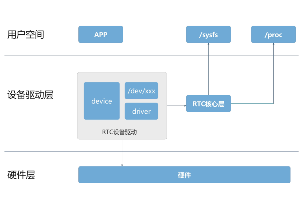
在上图中 RTC 子系统被划分为了三个层次,分别为用户空间、设备驱动层和硬件层,设备驱动层又包括 RTC 设备驱动和 RTC 核心层:
用户空间是应用程序运行的层级,在这一层,应用程序通过不同的接口与系统进行交互,比如访问
/dev/xxx设备节点来读写 RTC 时间,或通过sysfs和proc文件系统来获取或设置硬件状态。中间的设备驱动层又分为了 RTC 设备驱动和 RTC 核心层。
- RTC 设备驱动负责操作硬件的具体细节,通过与硬件(RTC 芯片)进行直接通信来实现硬件控制,设备驱动程序还负责将硬件设备暴露给上层系统,如
device(设备文件)和driver(驱动程序)。/dev/xxx是指用于操作设备的接口文件,用户应用程序通过它与 RTC 硬件进行交互。driver部分则是系统内核的一个模块,负责具体的硬件控制操作。
- RTC 核心层负责管理和协调 RTC 的时间管理功能。它确保系统正确地读取和设置时间,同时确保时钟在断电时继续运行。
- RTC 设备驱动负责操作硬件的具体细节,通过与硬件(RTC 芯片)进行直接通信来实现硬件控制,设备驱动程序还负责将硬件设备暴露给上层系统,如
RTC 硬件层代表实际的 RTC 硬件,通过硬件接口(如 I2C、SPI 等)与设备驱动层进行通信,提供实际的时间计时功能。
RTC 驱动源码分析
设备树
123456789101112 | //RTC 芯片使能&i2c5 { status = "okay"; rx8010: rx8010@32 { compatible = "epson,rx8010"; reg = <0x32>; status = "okay"; };}; |
通过 compatible 属性epson,rx8010找到匹配的驱动文件,驱动的具体路径为drivers/rtc/rtc-rx8010.c,先来找到驱动的入口函数:
12345678910 | static struct i2c_driver rx8010_driver = { .driver = { .name = "rtc-rx8010", .of_match_table = of_match_ptr(rx8010_of_match), }, .probe = rx8010_probe, .id_table = rx8010_id,};module_i2c_driver(rx8010_driver); |
module_i2c_driver()
这个宏是用来简化 I2C 设备驱动的注册和注销过程的,定义在include/linux/i2c.h文件中,具体如下所示。
123456789101112 | /** * module_i2c_driver() - Helper macro for registering a modular I2C driver * @__i2c_driver: i2c_driver struct * * Helper macro for I2C drivers which do not do anything special in module * init/exit. This eliminates a lot of boilerplate. Each module may only * use this macro once, and calling it replaces module_init() and module_exit() */ |
module_driver()
module_driver宏也是一个用来简化的宏,对应的宏定义如下所示
include/linux/device/driver.h
12345678910111213141516171819202122232425 | /** * module_driver() - Helper macro for drivers that don't do anything * special in module init/exit. This eliminates a lot of boilerplate. * Each module may only use this macro once, and calling it replaces * module_init() and module_exit(). * * @__driver: driver name * @__register: register function for this driver type * @__unregister: unregister function for this driver type * @...: Additional arguments to be passed to __register and __unregister. * * Use this macro to construct bus specific macros for registering * drivers, and do not use it on its own. */ |
最后来对上述宏进行代入,展开可以得到如下内容:
1234567891011 | static int __init rx8010_driver_init(void){ return i2c_add_driver(&rx8010_driver);}module_init(rx8010_driver_init);static void __exit rx8010_driver_exit(void){ i2c_del_driver(&rx8010_driver);}module_exit(rx8010_driver_exit); |
rx8010_driver_init函数在模块加载时被调用,它通过i2c_add_driver函数将rx8010_driver注册到内核中。rx8010_driver_exit函数在模块卸载时被调用,它通过i2c_del_driver函数将rx8010_driver从内核中注销。
rx8010_probe()
当 compatible 匹配之后会进入到 probe 函数,probe 函数内容如下所示。
123456789101112131415161718192021222324252627282930313233343536373839404142434445464748495051525354555657585960616263 | static int rx8010_probe(struct i2c_client *client, const struct i2c_device_id *id){ struct i2c_adapter *adapter = to_i2c_adapter(client->dev.parent);// 获取 I2C 适配器对象,用于检查功能支持 const struct rtc_class_ops *rtc_ops;// RTC 操作函数指针 struct rx8010_data *rx8010;// 用于存储设备私有数据的结构体 int err = 0;// 错误码初始化为 0 // 检查 I2C 适配器是否支持所需的 SMBus 字节数据和块数据功能 if (!i2c_check_functionality(adapter, I2C_FUNC_SMBUS_BYTE_DATA | I2C_FUNC_SMBUS_I2C_BLOCK)) { dev_err(&adapter->dev, "doesn't support required functionality\n"); return -EIO;// 如果不支持,打印错误信息并返回 -EIO(输入/输出错误) } // 分配一块清零的内存,并将其与设备生命周期绑定。 rx8010 = devm_kzalloc(&client->dev, sizeof(struct rx8010_data), GFP_KERNEL); if (!rx8010)// 如果内存分配失败,返回 -ENOMEM(内存不足错误) return -ENOMEM; // 初始化设备私有数据 rx8010->client = client; i2c_set_clientdata(client, rx8010); // 将私有数据与 I2C 客户端关联 // 初始化 RX8010 设备 err = rx8010_init_client(client); if (err) return err;// 如果初始化失败,直接返回错误码 if (client->irq > 0) {// 检查设备是否提供了中断号 dev_info(&client->dev, "IRQ %d supplied\n", client->irq); // 请求线程化的中断处理程序 err = devm_request_threaded_irq(&client->dev, client->irq, NULL, rx8010_irq_1_handler, IRQF_TRIGGER_LOW | IRQF_ONESHOT, "rx8010", client); if (err) { // 如果请求中断失败,打印错误信息并返回错误码 dev_err(&client->dev, "unable to request IRQ\n"); return err; } // 如果有中断支持,使用带有报警功能的 RTC 操作函数 rtc_ops = &rx8010_rtc_ops_alarm; } else { // 如果没有中断支持,使用默认的 RTC 操作函数 rtc_ops = &rx8010_rtc_ops_default; } // 注册 RTC 设备 rx8010->rtc = devm_rtc_device_register(&client->dev, client->name, rtc_ops, THIS_MODULE); if (IS_ERR(rx8010->rtc)) { // 如果注册失败,打印错误信息并返回错误码 dev_err(&client->dev, "unable to register the class device\n"); return PTR_ERR(rx8010->rtc); } rx8010->rtc->max_user_freq = 1;// 设置 RTC 设备的最大用户频率 return err;// 返回成功状态} |
probe 函数中定义了一个用于存储设备私有数据的rx8010_data结构体变量 rx8010,该结构体定义如下所示:
struct rx8010_data
12345 | struct rx8010_data { struct i2c_client *client; // I2C 客户端,用于与 RX8010 设备通信 struct rtc_device *rtc; // RTC 设备,用于管理实时时钟功能 u8 ctrlreg; // 控制寄存器的值,用于存储或配置 RX8010 的控制状态}; |
i2c_client是指向 I2C 客户端的指针,用于与 RX8010 设备通信,而rtc_device结构体表示与 RX8010 设备关联的 RTC(实时时钟)设备,该结构体的定义如下所示:
struct rtc_device
123456789101112131415161718192021222324252627282930313233343536373839404142434445464748495051525354555657585960 | struct rtc_device { struct device dev;// 设备结构体,用于与设备模型集成 struct module *owner;// 拥有该 RTC 设备的模块 int id;// RTC 设备的 ID const struct rtc_class_ops *ops;// RTC 设备的操作函数集 struct mutex ops_lock;// 用于保护操作函数集的互斥锁 struct cdev char_dev;// 字符设备,用于用户空间访问 RTC 设备 unsigned long flags;// RTC 设备的标志位 unsigned long irq_data;// 中断相关数据 spinlock_t irq_lock;// 用于保护中断数据的自旋锁 wait_queue_head_t irq_queue;// 等待队列,用于处理中断事件 struct fasync_struct *async_queue;// 异步通知队列 int irq_freq;// 中断频率 int max_user_freq;// 用户空间允许的最大中断频率 struct timerqueue_head timerqueue;// 定时器队列,用于管理定时器事件 struct rtc_timer aie_timer; // 闹钟中断定时器 struct rtc_timer uie_rtctimer; // 更新中断定时器 struct hrtimer pie_timer; /* sub second exp, so needs hrtimer */ // 高精度定时器,用于处理亚秒级的中断 int pie_enabled;// 高精度定时器是否启用 struct work_struct irqwork;// 中断处理的工作队列 /* Some hardware can't support UIE mode */ int uie_unsupported;// 硬件是否不支持更新中断模式 /* Number of nsec it takes to set the RTC clock. This influences when * the set ops are called. An offset: * - of 0.5 s will call RTC set for wall clock time 10.0 s at 9.5 s * - of 1.5 s will call RTC set for wall clock time 10.0 s at 8.5 s * - of -0.5 s will call RTC set for wall clock time 10.0 s at 10.5 s */ long set_offset_nsec;/* 设置 RTC 时钟时的偏移时间(纳秒) */ bool registered;// 设备是否已注册 /* Old ABI support */ bool nvram_old_abi;// 是否使用旧的 NVRAM ABI struct bin_attribute *nvram;// NVRAM 的二进制属性 time64_t range_min;// RTC 设备支持的最小时间范围 timeu64_t range_max;// RTC 设备支持的最大时间范围 time64_t start_secs;// RTC 设备的起始时间(秒) time64_t offset_secs;// RTC 设备的偏移时间(秒) bool set_start_time;// 是否设置了起始时间 struct work_struct uie_task;// 更新中断模拟任务 struct timer_list uie_timer;// 更新中断模拟定时器 /* Those fields are protected by rtc->irq_lock */ /* 以下字段由 rtc->irq_lock 保护 */ unsigned int oldsecs;// 上一次读取的秒数 unsigned int uie_irq_active:1;// 更新中断是否激活 unsigned int stop_uie_polling:1;// 是否停止更新中断轮询 unsigned int uie_task_active:1;// 更新中断任务是否激活 unsigned int uie_timer_active:1;// 更新中断定时器是否激活}; |
该结构体是 Linux 内核中 RTC 设备的核心数据结构,涵盖了 RTC 设备的所有功能和状态。
rx8010_init_client()
probe 函数中通过rx8010_init_client函数对 RX8010 芯片进行初始化和配置,由于不同的 RTC 芯片寄存器并不相同,因此初始化代码也不同。以下是对该函数的逐行分析。
1234567891011121314151617181920212223242526272829303132333435363738394041424344454647484950515253545556575859606162 | static int rx8010_init_client(struct i2c_client *client){ struct rx8010_data *rx8010 = i2c_get_clientdata(client); u8 ctrl[2]; int need_clear = 0, err = 0; u8 flag; flag = i2c_smbus_read_byte_data(client, RX8010_FLAG); if(flag < 0) return flag; flag &= ~(RX8010_FLAG_VLF); err = i2c_smbus_write_byte_data(client, RX8010_FLAG, flag); /* Initialize reserved registers as specified in datasheet */ err = i2c_smbus_write_byte_data(client, RX8010_RESV17, 0xD8); if (err < 0) return err; err = i2c_smbus_write_byte_data(client, RX8010_RESV30, 0x00); if (err < 0) return err; err = i2c_smbus_write_byte_data(client, RX8010_RESV31, 0x08); if (err < 0) return err; err = i2c_smbus_write_byte_data(client, RX8010_IRQ, 0x00); if (err < 0) return err; err = i2c_smbus_read_i2c_block_data(rx8010->client, RX8010_FLAG, 2, ctrl); if (err != 2) return err < 0 ? err : -EIO; if (ctrl[0] & RX8010_FLAG_VLF) dev_warn(&client->dev, "Frequency stop was detected\n"); if (ctrl[0] & RX8010_FLAG_AF) { dev_warn(&client->dev, "Alarm was detected\n"); need_clear = 1; } if (ctrl[0] & RX8010_FLAG_TF) need_clear = 1; if (ctrl[0] & RX8010_FLAG_UF) need_clear = 1; if (need_clear) { ctrl[0] &= ~(RX8010_FLAG_AF | RX8010_FLAG_TF | RX8010_FLAG_UF); err = i2c_smbus_write_byte_data(client, RX8010_FLAG, ctrl[0]); if (err < 0) return err; } rx8010->ctrlreg = (ctrl[1] & ~RX8010_CTRL_TEST); return 0;} |
struct rtc_class_ops
12345678910111213141516171819 | if (client->irq > 0) {// 检查设备是否提供了中断号 dev_info(&client->dev, "IRQ %d supplied\n", client->irq); // 请求线程化的中断处理程序 err = devm_request_threaded_irq(&client->dev, client->irq, NULL, rx8010_irq_1_handler, IRQF_TRIGGER_LOW | IRQF_ONESHOT, "rx8010", client); if (err) { // 如果请求中断失败,打印错误信息并返回错误码 dev_err(&client->dev, "unable to request IRQ\n"); return err; } // 如果有中断支持,使用带有报警功能的 RTC 操作函数 rtc_ops = &rx8010_rtc_ops_alarm;} else { // 如果没有中断支持,使用默认的 RTC 操作函数 rtc_ops = &rx8010_rtc_ops_default;} |
probe 函数中会根据设备是否提供了中断号来决定 RTC 芯片的操作模式,但无论是硬件连接还是设备树配置中都没有使用中断,所以进入的是第二个判断,也就是rtc_ops = &rx8010_rtc_ops_default;。
12345 | static const struct rtc_class_ops rx8010_rtc_ops_default = { .read_time = rx8010_get_time, // 读取当前时间的函数指针 .set_time = rx8010_set_time, // 设置当前时间的函数指针 .ioctl = rx8010_ioctl, // 提供额外控制功能的函数指针}; |
rx8010_rtc_ops_default为 RX8010 实时时钟芯片提供一组默认的操作函数接口,包括读取当前时间的函数指针、设置当前时间的函数指针以及 ioctl 额外控制功能
devm_rtc_device_register()
在 probe 函数中,使用devm_rtc_device_register函数注册 rtc 设备,该函数在drivers/rtc/class.c文件中,函数具体内容如下所示:
1234567891011121314151617181920212223242526272829303132333435 | /** * devm_rtc_device_register - resource managed rtc_device_register() * @dev: the device to register * @name: the name of the device (unused) * @ops: the rtc operations structure * @owner: the module owner * * @return a struct rtc on success, or an ERR_PTR on error * * Managed rtc_device_register(). The rtc_device returned from this function * are automatically freed on driver detach. * This function is deprecated, use devm_rtc_allocate_device and * rtc_register_device instead */struct rtc_device *devm_rtc_device_register(struct device *dev, const char *name, const struct rtc_class_ops *ops, struct module *owner){ struct rtc_device *rtc; int err; // 分配设备资源管理器的内存,用于存储 RTC 设备指针 rtc = devm_rtc_allocate_device(dev); if (IS_ERR(rtc)) return rtc;// 如果分配失败,返回错误指针(内存不足) rtc->ops = ops; err = __rtc_register_device(owner, rtc);// 调用 rtc_device_register 注册 RTC 设备 if (err) return ERR_PTR(err); return rtc;}EXPORT_SYMBOL_GPL(devm_rtc_device_register); |
__rtc_register_device()
1234567891011121314151617181920212223242526272829303132333435363738394041424344 | int __rtc_register_device(struct module *owner, struct rtc_device *rtc){ struct rtc_wkalrm alrm;// 用于存储报警信息 int err; if (!rtc->ops) { dev_dbg(&rtc->dev, "no ops set\n"); return -EINVAL; } rtc->owner = owner;// 设置模块所有者 rtc_device_get_offset(rtc);// 获取 RTC 设备的时间偏移量 /* Check to see if there is an ALARM already set in hw */ // 检查硬件中是否已经设置了报警 err = __rtc_read_alarm(rtc, &alrm);// 尝试读取硬件中的报警信息 if (!err && !rtc_valid_tm(&alrm.time))// 如果读取成功且时间有效 rtc_initialize_alarm(rtc, &alrm);// 初始化报警 rtc_dev_prepare(rtc);// 准备 RTC 设备的字符设备接口 // 将 RTC 设备的字符设备和设备结构体添加到内核 err = cdev_device_add(&rtc->char_dev, &rtc->dev); if (err) dev_warn(rtc->dev.parent, "failed to add char device %d:%d\n", MAJOR(rtc->dev.devt), rtc->id); else dev_dbg(rtc->dev.parent, "char device (%d:%d)\n", MAJOR(rtc->dev.devt), rtc->id); rtc_proc_add_device(rtc);// 将 RTC 设备添加到 proc 文件系统中 rtc->registered = true; dev_info(rtc->dev.parent, "registered as %s\n", dev_name(&rtc->dev)); if (!strcmp(dev_name(&rtc->dev), CONFIG_RTC_HCTOSYS_DEVICE)) rtc_hctosys(rtc); return 0;}EXPORT_SYMBOL_GPL(__rtc_register_device); |
该函数主要作用是注册一个 RTC 设备到 Linux 内核的 RTC 子系统中。它完成了一系列初始化和资源分配工作,使得内核可以通过标准接口与该 RTC 设备交互。
重点是调用了cdev_device_add函数,将 RTC 设备的字符设备和设备结构体注册到内核中,使 RTC 设备正式成为内核的一部分,可供用户空间或其他内核模块使用。
然后是其中的rtc_proc_add_device,将 RTC 设备的信息添加到 proc 子系统当中,便于调试和监控。
移植 RX8010 驱动

可以确定 RX8010 挂载到了 I2C5 上,所以需要在设备树的 i2c5 节点下添加 rx8010 的节点,添加内容如下所示:
123456789 | &i2c5 { status = "okay"; rx8010: rx8010@32 { compatible = "epson,rx8010"; reg = <0x32>; status = "okay"; };}; |
reg 属性表示 RX8010 的地址为 0x32,这里的地址可以根据 RX8010 数据手册得到,具体如下所示:

这里总共有 8 位的数据,这是因为在实际的数据传输过程中主设备发送的第一个字节包含了从设备地址和读/写位,其中从设备地址占字节的高 7 位(bit 7 到 bit 1),所以从上图可以得到 RX8010 的地址为 0110010,换算就可以得到 0x32 了。
然后来到 Linux 内核源码的根目录,使用 menuconfig 打开 RX8010 驱动。
123 | Device Drivers Real Time Clock <*> Epson RX8010SJ |
除此之外还要确保 RK 电源管理芯片的内部 RTC 没有被勾选,确保系统里面不会存在两个 RTC 设备。
123 | Device Drivers Real Time Clock <*> Rockchip RK805/RK808/RK809/RK816/RK817/RK818 RTC |
时间相关命令
date 命令
date 是 Linux 系统中一个非常强大的命令行工具,用于显示或设置系统的日期和时间。它不仅可以查看当前的系统时间,还可以设置系统时间、格式化日期和时间的输出、解析时间字符串并进行时间计算。
- 显示当前日期和时间
直接运行 date 命令会显示当前系统的日期和时间,格式为默认的本地时间格式,如下所示
12 | $ dateMon Jan 5 09:37:49 PM CST 2026 |
CST表示时区(China Standard Time)
- 设置系统时间
使用 date 命令可以设置系统时间的命令格式如下所示:
12345678 | date [MMDDhhmm[[CC]YY][.ss]]# MM:月份(两位数字,如 10 表示十月)。# DD:日期(两位数字,如 30 表示 30 日)。# hh:小时(24 小时制,两位数字,如 14 表示下午 2 点)。# mm:分钟(两位数字,如 23 表示 23 分钟)。# CC:世纪(可选,两位数字,如 20 表示 2000 年代)。# YY:年份(两位数字,如 23 表示 2023 年)。# .ss:秒数(可选,两位数字,如 .45 表示 45 秒)。 |
例如将系统时间设置为 2025 年 1 月 20 日 14:23:45:
1 | date 012014232025.45 |
- 格式化输出
date 命令支持通过格式化字符串自定义输出的日期和时间格式。在 date 命令后加上 + 和格式化字符串,可以指定输出格式。
| 格式符 | 描述 | 示例 |
|---|---|---|
%Y | 年份(四位数字) | 2023 |
%m | 月份(两位数字) | 10 |
%d | 日期(两位数字) | 30 |
%H | 小时(24小时制,两位数字) | 14 |
%I | 小时(12小时制,两位数字) | 02 |
%M | 分钟(两位数字) | 23 |
%S | 秒数(两位数字) | 45 |
%A | 星期几(完整名称) | Monday |
%a | 星期几(缩写名称) | Mon |
%B | 月份(完整名称) | October |
%b | 月份(缩写名称) | Oct |
%p | AM/PM | PM |
%Z | 时区 | CST |
例如,将格式为YYYY-MM-DD HH:MM:SS,并输出当前时间:
1 | date "+%Y-%m-%d %H:%M:%S" |
hwclock 命令
hwclock 是 Linux 系统中用于管理硬件时钟的命令行工具。包括查看、设置和同步硬件时钟与系统时钟。
- 查看硬件时钟
直接运行 hwclock 命令会显示当前硬件时钟的时间。
12 | $ sudo hwclock2026-01-05 21:52:44.991760+08:00 |
hwclock 命令显示的是硬件时钟的时间。硬件时钟通常默认存储的是 UTC 时间,UTC 是目前全球使用的标准时间,它是基于原子时钟的精确时间定义,并且不受地球自转变化的影响。
UTC 是全球时间的基准,不属于任何时区,因此它也被称为世界标准时间。
而 date 命令显示的是系统时钟的时间,系统时钟会根据操作系统的时区设置来调整时间。
上面打印的时区为 CST,即中国时区,那么 date 命令显示的时间会是 UTC+8。因此,系统时钟和硬件时钟使用不同的时间标准,导致二者之间的时间差。假设你在中国(UTC+8),那么两者的时间差正好是 8 小时。
- 同步硬件时钟与系统时钟
hwclock -s(--hctosys)将硬件时钟同步到系统时钟hwclock -w(--systohc)将系统时钟同步到硬件时钟
每次系统上电启动之后,都会将 RTC 里面的硬件时间同步到系统时间,具体的实现在内核drivers/rtc/class.c文件的rtc_hctosys函数。该函数的具体内容如下所示:
1234567891011121314151617181920212223242526272829303132333435363738394041424344454647484950 | /* Result of the last RTC to system clock attempt. */int rtc_hctosys_ret = -ENODEV;/* IMPORTANT: the RTC only stores whole seconds. It is arbitrary * whether it stores the most close value or the value with partial * seconds truncated. However, it is important that we use it to store * the truncated value. This is because otherwise it is necessary, * in an rtc sync function, to read both xtime.tv_sec and * xtime.tv_nsec. On some processors (i.e. ARM), an atomic read * of >32bits is not possible. So storing the most close value would * slow down the sync API. So here we have the truncated value and * the best guess is to add 0.5s. */static void rtc_hctosys(struct rtc_device *rtc){ int err; struct rtc_time tm;// 用于存储从 RTC 设备读取的时间 struct timespec64 tv64 = { .tv_nsec = NSEC_PER_SEC >> 1, // 设置纳秒部分为 0.5 秒(用于时间精度调整) }; // 从 RTC 设备读取当前时间 err = rtc_read_time(rtc, &tm); if (err) {// 如果读取时间失败 dev_err(rtc->dev.parent, "hctosys: unable to read the hardware clock\n"); goto err_read; } // 将 RTC 时间转换为 Unix 时间戳(自 1970 年 1 月 1 日以来的秒数) tv64.tv_sec = rtc_tm_to_time64(&tm); if (tv64.tv_sec > INT_MAX) {// 在 32 位系统上,检查时间戳是否超出范围 err = -ERANGE; // 如果超出范围,设置错误码为 "超出范围" goto err_read;// 跳转到错误处理标签 } err = do_settimeofday64(&tv64);// 将时间戳设置为系统时钟 dev_info(rtc->dev.parent, "setting system clock to %ptR UTC (%lld)\n", &tm, (long long)tv64.tv_sec);err_read: rtc_hctosys_ret = err;} |
通过rtc_read_time函数读取 RTC 硬件里面存储的时间,然后通过do_settimeofday64函数将转换之后的时间戳设置为系统时钟。
RTC 应用程序编写
ioctl宏定义解析
RTC_RD_TIME
1 | |
_IOR(type, nr, data_type):表示 从内核读取数据到用户空间。'p':魔数(magic number),用于区分不同设备的ioctl命令(RTC 固定为'p')。0x09:命令编号。struct rtc_time:期望的数据类型。
功能:读取 RTC 硬件当前时间(注意:不是系统时间!)
RTC_SET_TIME
1 | |
_IOW(type, nr, data_type):表示 从用户空间写入数据到内核。- 其他参数同上。
功能:将用户指定的时间写入 RTC 硬件(通常需要 root 权限)。
struct rtc_time结构体
这是 Linux 内核定义的标准时间结构(位于<linux/rtc.h>),与 C 标准库的struct tm几乎相同,但不保证完全兼容(尤其在跨平台时)。
| 字段 | 范围 | 说明 | ⚠️ 注意 |
|---|---|---|---|
tm_sec | 0–59 | 秒 | — |
tm_min | 0–59 | 分钟 | — |
tm_hour | 0–23 | 小时(24小时制) | — |
tm_mday | 1–31 | 日期(1号起) | 不是 0-based! |
tm_mon | 0–11 | 月份(0=Jan) | 容易出错! |
tm_year | 年份 - 1900 | 如 2023 →123 | 必须减 1900! |
tm_wday | 0–6 | 星期(0=Sun) | 驱动通常自动计算 |
tm_yday | 0–365 | 年内第几天 | 驱动通常自动计算 |
tm_isdst | 通常为 0 | 夏令时标志 | RTC 硬件一般不支持 |
关键陷阱:
- 设置 2023 年 2 月 15 日 →
.tm_year = 123,.tm_mon = 1- 打印时要加回去:
tm_year + 1900,tm_mon + 1
示例
12345678910111213141516171819202122232425262728293031323334353637383940414243444546474849505152535455565758596061626364656667 | int main() { int fd; struct rtc_time tm; // 必须以 O_RDWR 打开才能写 RTC fd = open("/dev/rtc0", O_RDWR); if (fd < 0) { perror("Failed to open /dev/rtc0 (try running as root)"); return EXIT_FAILURE; } // 读取当前 RTC 时间 if (ioctl(fd, RTC_RD_TIME, &tm) < 0) { perror("RTC_RD_TIME"); close(fd); return EXIT_FAILURE; } printf("Current RTC time: %d-%02d-%02d %02d:%02d:%02d\n", tm.tm_year + 1900, tm.tm_mon + 1, tm.tm_mday, tm.tm_hour, tm.tm_min, tm.tm_sec); // === 安全修改时间示例:设置为 2023-06-15 12:00:00 === // 注意:这里假设你要设置一个完整、合法的时间 tm.tm_year = 123; // 2023 tm.tm_mon = 5; // June (0-based) tm.tm_mday = 15; // 15th tm.tm_hour = 12; tm.tm_min = 0; tm.tm_sec = 0; // 可选:清零其他字段(驱动通常会自动计算 wday/yday) tm.tm_wday = tm.tm_yday = tm.tm_isdst = 0; // 写入 RTC if (ioctl(fd, RTC_SET_TIME, &tm) < 0) { if (errno == EPERM || errno == EACCES) { fprintf(stderr, "Error: Permission denied. Run as root or use 'sudo'.\n"); } else { perror("RTC_SET_TIME"); } close(fd); return EXIT_FAILURE; } // 验证写入结果 if (ioctl(fd, RTC_RD_TIME, &tm) < 0) { perror("RTC_RD_TIME (after set)"); close(fd); return EXIT_FAILURE; } printf("Modified RTC time: %d-%02d-%02d %02d:%02d:%02d\n", tm.tm_year + 1900, tm.tm_mon + 1, tm.tm_mday, tm.tm_hour, tm.tm_min, tm.tm_sec); close(fd); return EXIT_SUCCESS;} |
读取:通常普通用户可读(取决于 udev 规则)。
写入(
RTC_SET_TIME):需要 root 权限 或CAP_SYS_TIME能力。