
Timeline
Timeline
2026-01-05
init
This article introduces the basics of RTC (Real-Time Clock) in Linux systems, including its definition, main functions, application scenarios, and characteristics such as low power consumption, high precision, and independent operation. The article focuses on comparing two implementation schemes: internal RTC and external RTC. External RTC (such as the RX8010 chip on the iTOP-RK3568 development board) has high precision and strong independence, but is costly and complex to design. Internal RTC (such as the one built into the RK809 power management IC) is low-cost and simple to design, but has limited precision and relies on the main controller for power. Finally, the article analyzes the RTC peripheral circuit of the RK3568 development board. This circuit ensures that the RTC module can continue to work when the system is powered off by switching between the main power supply and a backup battery, so that time information is not lost.
Linux Driver Notes
| Table of Contents | Links |
|---|---|
| 1. Linux Driver Framework | |
| 2. Linux Driver Loading Logic | |
| 3. Character Device Basics | |
| 4. Concurrency and Race Conditions | |
| 5. Advanced Character Device Topics | |
| 6. Interrupts | |
| 7. Platform Bus | |
| 8. Device Tree | |
| 9. Device Model | |
| 10. Hotplug | |
| 11. pinctrl Subsystem | |
| 12. GPIO subsystem | |
| 13. Input subsystem | |
| 14. 1-Wire | |
| 15. I2C | |
| 16. SPI | |
| 17. UART | |
| 18. PWM | |
| 19. RTC | |
| 20. Watchdog | |
| 21. CAN | |
| 22. Network devices | |
| 23. ADC | |
| 24. IIO | |
| 25. USB | |
| 26. LCD |

RTC Basics
RTC Introduction
RTC(Real-Time Clock) that is,Real-Time Clock, is an integrated circuit or module used toprovide precise time information in electronic systems。
Unlike the system’s main processor (CPU),RTC is mainly responsible for maintaining the system’s real-time date and time,
Main Functions of RTC:
- Provide real-time time: RTC can continuously track the current date and time, usually including year, month, day, hour, minute, second and other information.
- Maintain time during power failure: RTC is usually equipped with a backup battery (such as a coin cell battery). Even if the main system loses power, the RTC can continue to run, ensuring that time information is not lost.
Application Scenarios of RTC:
- Electronic clocks: such as clock functions in devices like computers, mobile phones, and smart watches.
- Embedded systems: In industrial control and IoT devices, RTC is used to record the time when events occur.
- Data logging: In scenarios requiring timestamps, RTC provides accurate time information.
- Scheduled tasks: Used to periodically wake up the device or perform specific operations.
Characteristics of RTC:
- low power consumption: RTC is usually designed for low-power operation, suitable for long-term use.
- High precision: Can provide relatively accurate time information with small error.
- Independence: Even when the main system is powered off, the RTC can operate independently.
Internal RTC and External RTC
Real-time clocks have two common implementation approaches: external RTC and internal RTC.
An external RTC is a dedicated RTC chip independent of the main control chip, connected to the main control chip via communication interfaces such as I2C and SPI.。
- Advantages
- It features high precision and can provide more accurate time recording.
- The external RTC has an independent power management circuit and can be equipped with a button cell battery for long-term independent operation, ensuring continuity of time recording even if the main control chip is powered off or damaged.
- Disadvantages
- The external RTC has a higher cost, requiring additional procurement of the chip and related components, while also increasing the complexity of circuit design and development difficulty, and occupying communication resources of the main control chip.
Therefore, the external RTC is more suitable for scenarios with higher requirements for time accuracy, reliability, and functionality. The iTOP-RK3568 development board integrates an external RTC, using the RX8010 chip, as shown in the following figure:

The internal RTC is a real-time clock module integrated inside the main control chip.
- Advantages
- It features hardware integration and requires no additional hardware components, making the design simple, low-cost, and easy to use.
- Disadvantages
- The internal RTC relies on the power supply of the main control chip and usually requires a backup battery to maintain time recording after a power outage.
Internal RTC It is very susceptible to temperature and voltage fluctuations.,This leads to significant time drift.,Reliability is also relatively low. 。
Therefore, the internal RTC is more suitable for scenarios that are not demanding on time accuracy and are cost-sensitive, such as home appliances, simple IoT devices, or systems with low real-time requirements.
The power management chip RK809 on the iTOP-RK3568 core board integrates an internal RTC by default. However, due to the various disadvantages of the internal RTC mentioned above, and because the base board already has an external RTC, the internal RTC is not enabled. The internal RTC circuit of the RK809 power management chip is shown below:

Summary
| Category | Internal RTC | External RTC |
|---|---|---|
| Definition | RTC module integrated inside the main control chip | Independent dedicated RTC chip, connected via interfaces such as I²C/SPI |
| Features | - Hardware integration - Low power mode support - Depends on main controller power - Limited accuracy | - Independent operation - High accuracy - Multi-function expansion |
| Advantages | 1. Low cost 2. Simple design 3. Easy to use | 1. High accuracy 2. Strong independence 3. Rich features 4. High reliability |
| Disadvantages | 1. Insufficient accuracy 2. Lower reliability 3. Lack of independence | 1. Higher cost 2. Complex design 3. Resource consumption |
| Applicable scenarios | Systems with low time accuracy requirements, cost sensitivity, and low real-time requirements | Scenarios requiring high time accuracy, long-term independent operation, and additional functions |
RK3568 RTC peripheral
This circuit can be divided into the RTC power supply part and the RTC chip circuit part. According to the RTC chip circuit part, it can be seen that the RX8010 is mounted on I2C5.

The main function of this system is throughSwitching between main power supply mode and backup battery power supply mode, ensuring that the RTC module when the main power supply (VCC3V3_SYS) is powered off, can still continue to work through the backup battery (CR1220) to continue working, thereby keeping time information from being lost, divided into the following two cases:
- When the system is running normally,
VCC3V3_SYSprovides 3.3V power, diode D2 is forward-biased to supply power to the RTC module, while diode D3 is reverse-biased to prevent the main power supply from charging the battery or consuming battery power; - When the system is powered off (
VCC3V3_SYSfails), diode D2 is reverse-biased to prevent battery power from being consumed through the main power supply circuit, while diode D3 is forward-biased, andCR1220the battery supplies power to the RTC module, ensuring the RTC continues to run.
RX8010 Driver Analysis and Porting
RTC Subsystem Framework
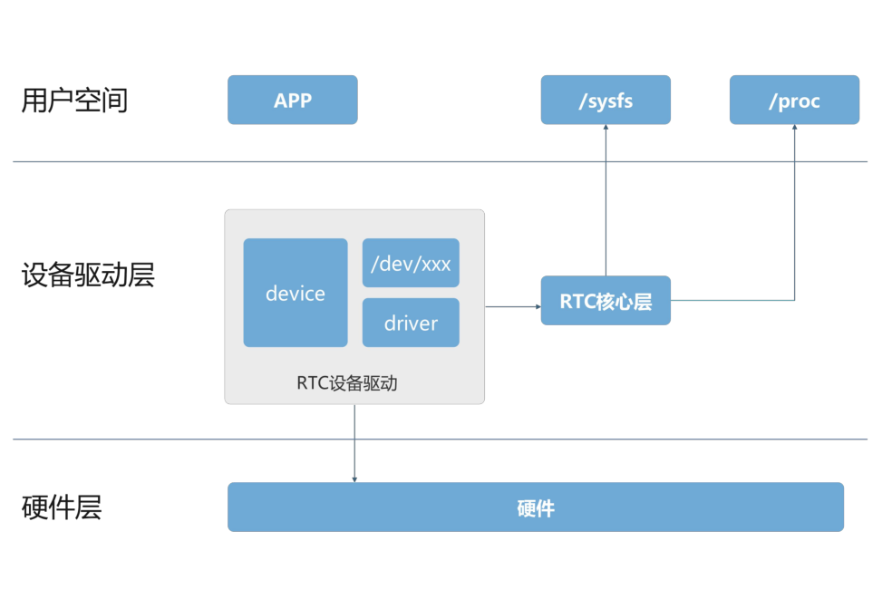
In the above figure, the RTC subsystem is divided into three layers: user space, device driver layer, and hardware layer. The device driver layer further includes the RTC device driver and the RTC core layer:
User space is the layer where applications run. At this layer, applications interact with the system through different interfaces, such as accessing
/dev/xxxdevice nodes to read and write RTC time, or throughsysfsandprocfile system to obtain or set hardware status.The middle device driver layer is further divided into the RTC device driver and the RTC core layer.
- The RTC device driver is responsible for the specific details of operating the hardware. It implements hardware control by communicating directly with the hardware (RTC chip). The device driver is also responsible for exposing the hardware device to the upper-level system, such as
device(device file) anddriver(driver)./dev/xxxrefers to the interface file used to operate the device, through which user applications interact with the RTC hardware.driverThe part is a module of the system kernel, responsible for specific hardware control operations.
- The RTC core layer is responsible for managing and coordinating the RTC’s time management functions. It ensures that the system correctly reads and sets the time, while also ensuring that the clock continues to run during power outages.
- The RTC device driver is responsible for the specific details of operating the hardware. It implements hardware control by communicating directly with the hardware (RTC chip). The device driver is also responsible for exposing the hardware device to the upper-level system, such as
The RTC hardware layer represents the actual RTC hardware. It communicates with the device driver layer through hardware interfaces (such as I2C, SPI, etc.) and provides the actual timekeeping function.
RTC Driver Source Code Analysis
Device Tree
123456789101112 | //RTC chip enable&i2c5 { status = "okay"; rx8010: rx8010@32 { compatible = "epson,rx8010"; reg = <0x32>; status = "okay"; };}; |
Through the compatible propertyepson,rx8010Find the matching driver file, the specific path of the driver isdrivers/rtc/rtc-rx8010.cFirst, let’s find the driver’s entry function:
12345678910 | static struct i2c_driver rx8010_driver = { .driver = { .name = "rtc-rx8010", .of_match_table = of_match_ptr(rx8010_of_match), }, .probe = rx8010_probe, .id_table = rx8010_id,};module_i2c_driver(rx8010_driver); |
module_i2c_driver()
This macro is used to simplify the registration and deregistration process of I2C device drivers, defined ininclude/linux/i2c.hfile, as shown below.
123456789101112 | /** * module_i2c_driver() - Helper macro for registering a modular I2C driver * @__i2c_driver: i2c_driver struct * * Helper macro for I2C drivers which do not do anything special in module * init/exit. This eliminates a lot of boilerplate. Each module may only * use this macro once, and calling it replaces module_init() and module_exit() */ |
module_driver()
module_driverThe macro is also a macro used for simplification, and the corresponding macro definition is as follows
include/linux/device/driver.h
12345678910111213141516171819202122232425 | /** * module_driver() - Helper macro for drivers that don't do anything * special in module init/exit. This eliminates a lot of boilerplate. * Each module may only use this macro once, and calling it replaces * module_init() and module_exit(). * * @__driver: driver name * @__register: register function for this driver type * @__unregister: unregister function for this driver type * @...: Additional arguments to be passed to __register and __unregister. * * Use this macro to construct bus specific macros for registering * drivers, and do not use it on its own. */ |
Finally, substitute the above macros, and the expansion yields the following:
1234567891011 | static int __init rx8010_driver_init(void){ return i2c_add_driver(&rx8010_driver);}module_init(rx8010_driver_init);static void __exit rx8010_driver_exit(void){ i2c_del_driver(&rx8010_driver);}module_exit(rx8010_driver_exit); |
rx8010_driver_initThe function is called when the module is loaded, and it uses thei2c_add_driverfunction torx8010_driverregister into the kernel.rx8010_driver_exitThe function is called when the module is unloaded, and it uses thei2c_del_driverfunction torx8010_driverunregister from the kernel.
rx8010_probe()
When the compatible matches, it enters the probe function. The probe function content is as follows.
123456789101112131415161718192021222324252627282930313233343536373839404142434445464748495051525354555657585960616263 | static int rx8010_probe(struct i2c_client *client, const struct i2c_device_id *id){ struct i2c_adapter *adapter = to_i2c_adapter(client->dev.parent);// Get the I2C adapter object to check feature support const struct rtc_class_ops *rtc_ops;// RTC operation function pointer struct rx8010_data *rx8010;// Structure for storing device private data int err = 0;// Error code initialized to 0 // Check whether the I2C adapter supports the required SMBus byte data and block data functions if (!i2c_check_functionality(adapter, I2C_FUNC_SMBUS_BYTE_DATA | I2C_FUNC_SMBUS_I2C_BLOCK)) { dev_err(&adapter->dev, "doesn't support required functionality\n"); return -EIO;// If not supported, print an error message and return -EIO (input/output error) } // Allocate a zeroed memory block and bind it to the device lifecycle. rx8010 = devm_kzalloc(&client->dev, sizeof(struct rx8010_data), GFP_KERNEL); if (!rx8010)// If memory allocation fails, return -ENOMEM (out of memory error) return -ENOMEM; // Initialize device private data rx8010->client = client; i2c_set_clientdata(client, rx8010); // Associate the private data with the I2C client // Initialize RX8010 device err = rx8010_init_client(client); if (err) return err;// If initialization fails, return the error code directly if (client->irq > 0) {// Check whether the device provides an interrupt number dev_info(&client->dev, "IRQ %d supplied\n", client->irq); // Request a threaded interrupt handler err = devm_request_threaded_irq(&client->dev, client->irq, NULL, rx8010_irq_1_handler, IRQF_TRIGGER_LOW | IRQF_ONESHOT, "rx8010", client); if (err) { // If requesting the interrupt fails, print an error message and return the error code dev_err(&client->dev, "unable to request IRQ\n"); return err; } // If interrupt support is available, use the RTC operation functions with alarm capability rtc_ops = &rx8010_rtc_ops_alarm; } else { // If interrupt support is not available, use the default RTC operation functions rtc_ops = &rx8010_rtc_ops_default; } // Register the RTC device rx8010->rtc = devm_rtc_device_register(&client->dev, client->name, rtc_ops, THIS_MODULE); if (IS_ERR(rx8010->rtc)) { // If registration fails, print an error message and return the error code dev_err(&client->dev, "unable to register the class device\n"); return PTR_ERR(rx8010->rtc); } rx8010->rtc->max_user_freq = 1;// Set the maximum user frequency of the RTC device return err;// Return success status} |
In the probe function, a variable for storing device private data is definedrx8010_datastructure variable rx8010, and the structure is defined as follows:
struct rx8010_data
12345 | struct rx8010_data { struct i2c_client *client; // I2C client, used to communicate with the RX8010 device struct rtc_device *rtc; // RTC device, used to manage the real-time clock function u8 ctrlreg; // Control register value, used to store or configure the control state of the RX8010}; |
i2c_clientis a pointer to the I2C client, used to communicate with the RX8010 device, andrtc_deviceThe structure represents the RTC (real-time clock) device associated with the RX8010 device, and the definition of the structure is as follows:
struct rtc_device
123456789101112131415161718192021222324252627282930313233343536373839404142434445464748495051525354555657585960 | struct rtc_device { struct device dev;// Device structure, used for integration with the device model struct module *owner;// The module that owns the RTC device int id;// ID of the RTC device const struct rtc_class_ops *ops;// Operation function set of the RTC device struct mutex ops_lock;// Mutex used to protect the operation function set struct cdev char_dev;// Character device, used for user-space access to the RTC device unsigned long flags;// Flag bits of the RTC device unsigned long irq_data;// Interrupt-related data spinlock_t irq_lock;// Spinlock for protecting interrupt data wait_queue_head_t irq_queue;// Wait queue for handling interrupt events struct fasync_struct *async_queue;// Asynchronous notification queue int irq_freq;// Interrupt frequency int max_user_freq;// Maximum interrupt frequency allowed by user space struct timerqueue_head timerqueue;// Timer queue for managing timer events struct rtc_timer aie_timer; // Alarm interrupt timer struct rtc_timer uie_rtctimer; // Update interrupt timer struct hrtimer pie_timer; /* sub second exp, so needs hrtimer */ // High-resolution timer for handling sub-second interrupts int pie_enabled;// Whether high-resolution timer is enabled struct work_struct irqwork;// Work queue for interrupt handling /* Some hardware can't support UIE mode */ int uie_unsupported;// Whether hardware does not support update interrupt mode /* Number of nsec it takes to set the RTC clock. This influences when * the set ops are called. An offset: * - of 0.5 s will call RTC set for wall clock time 10.0 s at 9.5 s * - of 1.5 s will call RTC set for wall clock time 10.0 s at 8.5 s * - of -0.5 s will call RTC set for wall clock time 10.0 s at 10.5 s */ long set_offset_nsec;/* Offset time (nanoseconds) when setting the RTC clock */ bool registered;// Whether the device is registered /* Old ABI support */ bool nvram_old_abi;// Whether to use old NVRAM ABI struct bin_attribute *nvram;// NVRAM binary attribute time64_t range_min;// Minimum time range supported by the RTC device timeu64_t range_max;// Maximum time range supported by the RTC device time64_t start_secs;// RTC device start time (seconds) time64_t offset_secs;// RTC device offset time (seconds) bool set_start_time;// Whether the start time is set struct work_struct uie_task;// Update interrupt simulation task struct timer_list uie_timer;// Update interrupt simulation timer /* Those fields are protected by rtc->irq_lock */ /* 以下字段由 rtc->irq_lock 保护 */ unsigned int oldsecs;// Seconds of the last read unsigned int uie_irq_active:1;// Whether the update interrupt is active unsigned int stop_uie_polling:1;// Whether to stop update interrupt polling unsigned int uie_task_active:1;// Whether the update interrupt task is active unsigned int uie_timer_active:1;// Whether the update interrupt timer is active}; |
This structure is the core data structure of the RTC device in the Linux kernel, covering all functions and states of the RTC device.
rx8010_init_client()
In the probe function, throughrx8010_init_clientThe function initializes and configures the RX8010 chip. Since different RTC chips have different registers, the initialization code also differs. The following is a line-by-line analysis of this function.
1234567891011121314151617181920212223242526272829303132333435363738394041424344454647484950515253545556575859606162 | static int rx8010_init_client(struct i2c_client *client){ struct rx8010_data *rx8010 = i2c_get_clientdata(client); u8 ctrl[2]; int need_clear = 0, err = 0; u8 flag; flag = i2c_smbus_read_byte_data(client, RX8010_FLAG); if(flag < 0) return flag; flag &= ~(RX8010_FLAG_VLF); err = i2c_smbus_write_byte_data(client, RX8010_FLAG, flag); /* Initialize reserved registers as specified in datasheet */ err = i2c_smbus_write_byte_data(client, RX8010_RESV17, 0xD8); if (err < 0) return err; err = i2c_smbus_write_byte_data(client, RX8010_RESV30, 0x00); if (err < 0) return err; err = i2c_smbus_write_byte_data(client, RX8010_RESV31, 0x08); if (err < 0) return err; err = i2c_smbus_write_byte_data(client, RX8010_IRQ, 0x00); if (err < 0) return err; err = i2c_smbus_read_i2c_block_data(rx8010->client, RX8010_FLAG, 2, ctrl); if (err != 2) return err < 0 ? err : -EIO; if (ctrl[0] & RX8010_FLAG_VLF) dev_warn(&client->dev, "Frequency stop was detected\n"); if (ctrl[0] & RX8010_FLAG_AF) { dev_warn(&client->dev, "Alarm was detected\n"); need_clear = 1; } if (ctrl[0] & RX8010_FLAG_TF) need_clear = 1; if (ctrl[0] & RX8010_FLAG_UF) need_clear = 1; if (need_clear) { ctrl[0] &= ~(RX8010_FLAG_AF | RX8010_FLAG_TF | RX8010_FLAG_UF); err = i2c_smbus_write_byte_data(client, RX8010_FLAG, ctrl[0]); if (err < 0) return err; } rx8010->ctrlreg = (ctrl[1] & ~RX8010_CTRL_TEST); return 0;} |
struct rtc_class_ops
12345678910111213141516171819 | if (client->irq > 0) {// Check whether the device provides an interrupt number dev_info(&client->dev, "IRQ %d supplied\n", client->irq); // Request a threaded interrupt handler err = devm_request_threaded_irq(&client->dev, client->irq, NULL, rx8010_irq_1_handler, IRQF_TRIGGER_LOW | IRQF_ONESHOT, "rx8010", client); if (err) { // If requesting the interrupt fails, print an error message and return the error code dev_err(&client->dev, "unable to request IRQ\n"); return err; } // If interrupt support is available, use the RTC operation functions with alarm capability rtc_ops = &rx8010_rtc_ops_alarm;} else { // If interrupt support is not available, use the default RTC operation functions rtc_ops = &rx8010_rtc_ops_default;} |
In the probe function, the operation mode of the RTC chip is determined by whether the device provides an interrupt number. However, since interrupts are not used in either the hardware connection or the device tree configuration, the second branch is taken, namelyrtc_ops = &rx8010_rtc_ops_default;。
12345 | static const struct rtc_class_ops rx8010_rtc_ops_default = { .read_time = rx8010_get_time, // Function pointer for reading the current time .set_time = rx8010_set_time, // Function pointer for setting the current time .ioctl = rx8010_ioctl, // Function pointer for providing additional control functions}; |
rx8010_rtc_ops_defaultProvides a set of default operation function interfaces for the RX8010 real-time clock chip, including a function pointer for reading the current time, a function pointer for setting the current time, and additional ioctl control functions.
devm_rtc_device_register()
In the probe function, usedevm_rtc_device_registerThe function registers the RTC device. This function is indrivers/rtc/class.cIn the file, the function is as follows:
1234567891011121314151617181920212223242526272829303132333435 | /** * devm_rtc_device_register - resource managed rtc_device_register() * @dev: the device to register * @name: the name of the device (unused) * @ops: the rtc operations structure * @owner: the module owner * * @return a struct rtc on success, or an ERR_PTR on error * * Managed rtc_device_register(). The rtc_device returned from this function * are automatically freed on driver detach. * This function is deprecated, use devm_rtc_allocate_device and * rtc_register_device instead */struct rtc_device *devm_rtc_device_register(struct device *dev, const char *name, const struct rtc_class_ops *ops, struct module *owner){ struct rtc_device *rtc; int err; // Allocate memory from the device resource manager to store the RTC device pointer rtc = devm_rtc_allocate_device(dev); if (IS_ERR(rtc)) return rtc;// If allocation fails, return an error pointer (out of memory). rtc->ops = ops; err = __rtc_register_device(owner, rtc);// Call rtc_device_register registers the RTC device if (err) return ERR_PTR(err); return rtc;}EXPORT_SYMBOL_GPL(devm_rtc_device_register); |
__rtc_register_device()
1234567891011121314151617181920212223242526272829303132333435363738394041424344 | int __rtc_register_device(struct module *owner, struct rtc_device *rtc){ struct rtc_wkalrm alrm;// Used to store alarm information. int err; if (!rtc->ops) { dev_dbg(&rtc->dev, "no ops set\n"); return -EINVAL; } rtc->owner = owner;// Set module owner rtc_device_get_offset(rtc);// Get the time offset of the RTC device /* Check to see if there is an ALARM already set in hw */ // Check whether an alarm has already been set in the hardware err = __rtc_read_alarm(rtc, &alrm);// Attempt to read the alarm information from the hardware if (!err && !rtc_valid_tm(&alrm.time))// If the read succeeds and the time is valid rtc_initialize_alarm(rtc, &alrm);// Initialize the alarm rtc_dev_prepare(rtc);// Prepare the character device interface of the RTC device // Add the RTC device's character device and device structure to the kernel err = cdev_device_add(&rtc->char_dev, &rtc->dev); if (err) dev_warn(rtc->dev.parent, "failed to add char device %d:%d\n", MAJOR(rtc->dev.devt), rtc->id); else dev_dbg(rtc->dev.parent, "char device (%d:%d)\n", MAJOR(rtc->dev.devt), rtc->id); rtc_proc_add_device(rtc);// Add the RTC device to the proc file system rtc->registered = true; dev_info(rtc->dev.parent, "registered as %s\n", dev_name(&rtc->dev)); if (!strcmp(dev_name(&rtc->dev), CONFIG_RTC_HCTOSYS_DEVICE)) rtc_hctosys(rtc); return 0;}EXPORT_SYMBOL_GPL(__rtc_register_device); |
The main purpose of this function is to register an RTC device into the Linux kernel’s RTC subsystem. It completes a series of initialization and resource allocation tasks, enabling the kernel to interact with the RTC device through standard interfaces.
The key point is the call tocdev_device_addfunction, which registers the RTC device’s character device and device structure into the kernel, making the RTC device officially part of the kernel and available for use by user space or other kernel modules.
Then there is thertc_proc_add_device, which adds the RTC device information to the proc subsystem for debugging and monitoring.
Porting the RX8010 driver

It can be determined that the RX8010 is mounted on I2C5, so it is necessary to add an rx8010 node under the i2c5 node in the device tree. The added content is as follows:
123456789 | &i2c5 { status = "okay"; rx8010: rx8010@32 { compatible = "epson,rx8010"; reg = <0x32>; status = "okay"; };}; |
The reg attribute indicates that the address of the RX8010 is 0x32. This address can be obtained from the RX8010 datasheet, as shown below:

There are 8 bits of data in total here, because in the actual data transmission processThe first byte sent by the master device contains the slave device address and the read/write bit, where the slave device address occupies the upper 7 bits of the byte (bit 7 to bit 1), so from the figure above, the address of the RX8010 is 0110010, which can be converted to 0x32.
Then go to the root directory of the Linux kernel source code and use menuconfig to enable the RX8010 driver.
123 | Device Drivers Real Time Clock <*> Epson RX8010SJ |
In addition, make sure that the internal RTC of the RK power management chip is not selected, to ensure that there are not two RTC devices in the system.
123 | Device Drivers Real Time Clock <*> Rockchip RK805/RK808/RK809/RK816/RK817/RK818 RTC |
Time-related commands
date command
date is a very powerful command-line tool in Linux systems, used to display or set the system date and time. It can not only view the current system time, but also set the system time, format the output of date and time, parse time strings, and perform time calculations.
- Display current date and time
Running the date command directly will display the current system date and time in the default local time format, as shown below:
12 | $ dateMon Jan 5 09:37:49 PM CST 2026 |
CST indicates the time zone (China Standard Time)
- Set system time
The command format for setting the system time using the date command is as follows:
12345678 | date [MMDDhhmm[[CC]YY][.ss]]# MM: month (two digits, e.g., 10 means October).# DD: day (two digits, e.g., 30 means the 30th day).# hh: hour (24-hour format, two digits, e.g., 14 means 2 PM).# mm: minute (two digits, e.g., 23 means 23 minutes).# CC: century (optional, two digits, e.g., 20 means the 2000s).# YY: year (two digits, e.g., 23 means 2023).# .ss: seconds (optional, two digits, e.g., .45 means 45 seconds). |
For example, to set the system time to January 20, 2025, 14:23:45:
1 | date 012014232025.45 |
- Formatting output
The date command supports customizing the output date and time format through format strings. By adding + and a format string after the date command, you can specify the output format.
| Format specifiers | Description | example |
|---|---|---|
%Y | Year (four digits) | 2023 |
%m | Month (two digits) | 10 |
%d | Day (two digits) | 30 |
%H | Hour (24-hour format, two digits) | 14 |
%I | Hour (12-hour format, two digits) | 02 |
%M | Minutes (two digits) | 23 |
%S | Seconds (two digits) | 45 |
%A | Day of the week (full name) | Monday |
%a | Day of the week (abbreviated name) | Mon |
%B | Month (full name) | October |
%b | Month (abbreviated name) | Oct |
%p | AM/PM | PM |
%Z | Time zone | CST |
For example, set the format toYYYY-MM-DD HH:MM:SS, and output the current time:
1 | date "+%Y-%m-%d %H:%M:%S" |
hwclock command
hwclock is a command-line tool in Linux used tomanage the hardware clockIt includes viewing, setting, and synchronizing the hardware clock with the system clock.
- Viewing the hardware clock
Running the hwclock command directly will display the current hardware clock time.
12 | $ sudo hwclock2026-01-05 21:52:44.991760+08:00 |
The hwclock command displays the hardware clock time. The hardware clock typically stores UTC time by default. UTC is the standard time used worldwide today, based on the precise time definition of atomic clocks and unaffected by variations in the Earth’s rotation.
UTC is the global time reference and does not belong to any time zone, so it is also known as the world standard time.
The date command, on the other hand, displays the system clock time, which is adjusted according to the operating system’s time zone settings.
The time zone printed above is CST, which is the China time zone, so the time displayed by the date command will be UTC+8. Therefore, the system clock and the hardware clock use different time standards, resulting in a time difference between the two. If you are in China (UTC+8), the time difference between the two is exactly 8 hours.
- Synchronizing the hardware clock and the system clock
hwclock -s(--hctosys) Synchronize the hardware clock to the system clockhwclock -w(--systohc) Synchronize the system clock to the hardware clock
After each system power-on, the hardware time in the RTC is synchronized to the system time. The specific implementation is in the kerneldrivers/rtc/class.cfile’srtc_hctosysfunction. The specific content of this function is as follows:
1234567891011121314151617181920212223242526272829303132333435363738394041424344454647484950 | /* Result of the last RTC to system clock attempt. */int rtc_hctosys_ret = -ENODEV;/* IMPORTANT: the RTC only stores whole seconds. It is arbitrary * whether it stores the most close value or the value with partial * seconds truncated. However, it is important that we use it to store * the truncated value. This is because otherwise it is necessary, * in an rtc sync function, to read both xtime.tv_sec and * xtime.tv_nsec. On some processors (i.e. ARM), an atomic read * of >32bits is not possible. So storing the most close value would * slow down the sync API. So here we have the truncated value and * the best guess is to add 0.5s. */static void rtc_hctosys(struct rtc_device *rtc){ int err; struct rtc_time tm;// Used to store the time read from the RTC device struct timespec64 tv64 = { .tv_nsec = NSEC_PER_SEC >> 1, // Set the nanosecond part to 0.5 seconds (for time precision adjustment) }; // Read the current time from the RTC device err = rtc_read_time(rtc, &tm); if (err) {// If reading the time fails dev_err(rtc->dev.parent, "hctosys: unable to read the hardware clock\n"); goto err_read; } // Convert RTC time to Unix timestamp (seconds since January 1, 1970) tv64.tv_sec = rtc_tm_to_time64(&tm); if (tv64.tv_sec > INT_MAX) {// On 32-bit systems, check whether the timestamp is out of range err = -ERANGE; // If out of range, set the error code to "out of range" goto err_read;// Jump to the error handling label } err = do_settimeofday64(&tv64);// Set the system clock to the timestamp dev_info(rtc->dev.parent, "setting system clock to %ptR UTC (%lld)\n", &tm, (long long)tv64.tv_sec);err_read: rtc_hctosys_ret = err;} |
Through thertc_read_timeThe function reads the time stored in the RTC hardware, and then throughdo_settimeofday64The function sets the converted timestamp as the system clock.
RTC application programming
ioctlMacro definition parsing
RTC_RD_TIME
1 | |
_IOR(type, nr, data_type): indicates Read data from the kernel to user space。'p': magic number, used to distinguish different devicesioctlcommand (RTC is fixed to'p')。0x09: command number.struct rtc_time: expected data type.
Function:Read the current time from RTC hardware(Note: not the system time!)
RTC_SET_TIME
1 | |
_IOW(type, nr, data_type): indicates Write data from user space to the kernel。- Other parameters are the same as above.
Function:Write the user-specified time to the RTC hardware(Usually requires root privileges).
struct rtc_timeStruct
This is the standard time structure defined by the Linux kernel (located in<linux/rtc.h>), and the C standard library’sstruct tmAlmost identical, butnot guaranteed to be fully compatible(especially when cross-platform).
| field | Range | Description | ⚠️ Note |
|---|---|---|---|
tm_sec | 0–59 | Seconds | — |
tm_min | 0–59 | Minutes | — |
tm_hour | 0–23 | Hours (24-hour clock) | — |
tm_mday | 1–31 | Date (starting from 1) | Not 0-based! |
tm_mon | 0–11 | Month (0=Jan) | Error-prone! |
tm_year | Year - 1900 | e.g., 2023 →123 | Must subtract 1900! |
tm_wday | 0–6 | Weekday (0=Sun) | Driver usually calculates automatically |
tm_yday | 0–365 | Day of year | Driver usually calculates automatically |
tm_isdst | Usually 0 | Daylight saving time flag | RTC hardware generally does not support |
Key pitfalls:
- Set February 15, 2023 →
.tm_year = 123,.tm_mon = 1- Add it back when printing:
tm_year + 1900,tm_mon + 1
example
12345678910111213141516171819202122232425262728293031323334353637383940414243444546474849505152535455565758596061626364656667 | int main() { int fd; struct rtc_time tm; // Must be opened with O_RDWR to write to the RTC fd = open("/dev/rtc0", O_RDWR); if (fd < 0) { perror("Failed to open /dev/rtc0 (try running as root)"); return EXIT_FAILURE; } // Read the current RTC time if (ioctl(fd, RTC_RD_TIME, &tm) < 0) { perror("RTC_RD_TIME"); close(fd); return EXIT_FAILURE; } printf("Current RTC time: %d-%02d-%02d %02d:%02d:%02d\n", tm.tm_year + 1900, tm.tm_mon + 1, tm.tm_mday, tm.tm_hour, tm.tm_min, tm.tm_sec); // === Example of safely modifying the time: set to 2023-06-15 12:00:00 === // Note: This assumes you want to set a complete, valid time tm.tm_year = 123; // 2023 tm.tm_mon = 5; // June (0-based) tm.tm_mday = 15; // 15th tm.tm_hour = 12; tm.tm_min = 0; tm.tm_sec = 0; // Optional: Clear other fields (the driver usually calculates wday/yday automatically) tm.tm_wday = tm.tm_yday = tm.tm_isdst = 0; // Write to the RTC if (ioctl(fd, RTC_SET_TIME, &tm) < 0) { if (errno == EPERM || errno == EACCES) { fprintf(stderr, "Error: Permission denied. Run as root or use 'sudo'.\n"); } else { perror("RTC_SET_TIME"); } close(fd); return EXIT_FAILURE; } // Verify the write result if (ioctl(fd, RTC_RD_TIME, &tm) < 0) { perror("RTC_RD_TIME (after set)"); close(fd); return EXIT_FAILURE; } printf("Modified RTC time: %d-%02d-%02d %02d:%02d:%02d\n", tm.tm_year + 1900, tm.tm_mon + 1, tm.tm_mday, tm.tm_hour, tm.tm_min, tm.tm_sec); close(fd); return EXIT_SUCCESS;} |
Read: Usually readable by normal users (depends on udev rules).
Write (
RTC_SET_TIME):requires root privileges orCAP_SYS_TIMEcapability.