
Timeline
Timeline
2026-01-13
init
This article introduces the basics of network communication related to Linux network devices, including the history of network development, the characteristics and functions of common protocols such as TCP/IP, UDP, DNS, DHCP, FTP, and HTTP/HTTPS, as well as transmission media such as network cables, cables, and optical fibers, and types of network cables.
Linux Driver Notes
| Table of Contents | Links |
|---|---|
| 1. Linux Driver Framework | |
| 2. Linux Driver Loading Logic | |
| 3. Character Device Basics | |
| 4. Concurrency and Race Conditions | |
| 5. Advanced Character Device Topics | |
| 6. Interrupts | |
| 7. Platform Bus | |
| 8. Device Tree | |
| 9. Device Model | |
| 10. Hotplug | |
| 11. pinctrl Subsystem | |
| 12. GPIO subsystem | |
| 13. Input subsystem | |
| 14. 1-Wire | |
| 15. I2C | |
| 16. SPI | |
| 17. UART | |
| 18. PWM | |
| 19. RTC | |
| 20. Watchdog | |
| 21. CAN | |
| 22. Network devices | |
| 23. ADC | |
| 24. IIO | |
| 25. USB | |
| 26. LCD |

Network Communication Basics
Development History
In 1969, ARPANET initially connected computers at four American universities, using packet-switching technology to achieve data transmission between computers.
In 1972, the first transatlantic connection with computers in the United Kingdom and Norway was established.
In 1973, research began on the Transmission Control Protocol (TCP) and the Internet Protocol (IP).
In 1984, the TCP/IP protocol became the standard for computer network communication.
In 1986, the U.S. National Science Foundation (NSF) established a wide area network (the predecessor of the Internet).
In 1994, China’s NCFC network was officially connected to NSFnet, and China joined the Internet.
Network Protocols
Network protocols are the rules and conventions for devices to communicate in a network. Common network protocols include:
TCP/IP Protocol
TCP/IP (Transmission Control Protocol/Internet Protocol), namely the Transmission Control Protocol/Internet Protocol, is the fundamental protocol suite used for Internet communication.
Features
- connection-oriented: Before transmitting data, the TCP protocol establishes a connection through a ‘three-way handshake’ to ensure the reliability of both communicating parties and the orderly transmission of data.
- High reliability: TCP uses mechanisms such as sequence numbers, acknowledgment replies, retransmission, and flow control to ensure the reliability and integrity of data. If a data packet is lost or corrupted during transmission, TCP will request retransmission until the data arrives accurately and without error.
- Byte-stream based: TCP treats application-layer data as an unstructured byte stream and does not preserve message boundaries. This indicates that TCP does not care about the specific content of application-layer data, but merely transmits it as a series of bytes.
Function
- The TCP/IP protocol adopts a layered working approach, with each layer performing specific functions, providing a complete communication solution from network hardware to applications. This enables data exchange between different computers and networks.
UDP Protocol
UDP (User Datagram Protocol) is the User Datagram Protocol. Unlike TCP, UDP does not provide a connection-oriented communication method, nor does it ensure the reliability and integrity of data.
Features
Connectionless: UDP does not need to establish a connection before sending data. Each data packet is sent independently, and the receiver does not need to send an acknowledgment. This characteristic gives UDP lower latency and higher transmission efficiency.
Unreliability: UDP cannot guarantee the order, integrity, and reliability of data packets. If packets are lost or corrupted during transmission, UDP will not request retransmission.
Datagram-based: UDP encapsulates application-layer data into independent datagrams for transmission, each containing complete destination and source address information.
Function
UDP is suitable for scenarios with high real-time requirements, such as video streaming, audio streaming, and online gaming. In these applications, even if a small number of packets are lost, it will not seriously affect the overall experience.
DNS Protocol
DNS (Domain Name System) is a distributed database system whose main function is to convert domain names into corresponding IP addresses (e.g., 192.0.2.1). With DNS, users can access websites through easy-to-remember domain names without having to memorize complex IP addresses.
DHCP Protocol
DHCP (Dynamic Host Configuration Protocol) is a network protocol that automatically assigns network parameters such as IP addresses, subnet masks, default gateways, and DNS server addresses to client devices on a local area network.
FTP Protocol
FTP (File Transfer Protocol) is a protocol for network file transfer, used to achieve file sharing between different computers, and is one of the important tools for file transfer on the Internet.
HTTP/HTTPS Protocol
HTTP (HyperText Transfer Protocol) is an application-layer protocol for distributed, collaborative, hypermedia information systems, and is the foundation of data communication on the World Wide Web (WWW).
HTTPS (HyperText Transfer Protocol Secure) is the secure version of HTTP. It encrypts data through the SSL/TLS protocol, thereby ensuring the security of data transmission.
Function
The HTTP protocol enables users to access various resources on the Internet through browsers, such as web pages, images, and videos. The HTTPS protocol is dedicated to protecting users’ data security, preventing data from being stolen or tampered with during transmission, and is widely used in scenarios with high data security requirements, such as online banking, online payment, and e-commerce.
Transmission Medium
Including network cables, electrical cables, and optical fibers.
- Network Cable
A network cable is generally composed of several conductors, commonly 8 copper conductors twisted together in pairs to form 4 twisted pairs. The outside is wrapped with an insulating layer and a sheath, which protect the internal conductors and prevent information leakage and external electromagnetic interference.
- Cable
A cable is a device for transmitting electrical energy or signals, usually composed of several or several groups of conductors. A cable consists of conductors, an insulating layer, and a sheath layer.
- Optical Fiber
Optical fiber is a cable that uses light as the information carrier and transmits data by utilizing the principle of total internal reflection of light in fibers made of glass or plastic. It is mainly divided into single-mode fiber and multi-mode fiber.
Types of Network Cables
Category 1 and Category 2 cables
Category 1 and Category 2 cables were mainly used in early telephone communication systems and did not support data transmission or network applications in the modern sense. With the continuous advancement of network technology, these two types of cables have been phased out and are no longer used for network cabling.
Category 3 cable (Category 3, Cat 3)
Category 3 cable is one of the early Ethernet cable standards, mainly used for traditional Ethernet with a transmission rate of 10Mbps. In modern network environments, Category 3 cables are rarely used.
Category 4 network cable (Category 4, Cat 4)
Compared with Category 3 cable, Category 4 cable was improved, but in practical applications, due to its low cost-performance ratio, it was not widely promoted and was soon replaced by the more advanced Category 5 cable.
Category 5 cable (Category 5, Cat 5)
Category 5e cable (Category 5e, Cat 5e)
Category 6 cable (Category 6, Cat 6)
Category 6A cable (Category 6A, Cat 6a)
Augmented 6 Category cable is 6 A further upgraded version of the category cable,Supports 10Gbps transmission rate(10 Gigabit Ethernet)。Category 7 cable (Category 7, Cat 7)
7 Category cable is a shielded twisted pair(STP),Supports 10Gbps transmission rate,has higher bandwidth and lower signal attenuation rate。Network cable wiring standards
There are two standards for making network cables, namely T568A and T568B.
If both ends of the network cable use the same wiring standard, it is called a straight-through cable, used to connect different types of devices, such as a computer and a router.
If the wiring orders at the two ends are different, for example one end is T568A and the other is T568B, it is called a crossover cable, often used to connect devices of the same type, such as computer to computer, switch to switch.
T568A
T568A standard wiring order: green-white, green, orange-white, blue, blue-white, orange, brown-white, brown.

T568B
T568B standard wiring order: orange-white, orange, green-white, blue, blue-white, green, brown-white, brown

Network model
OSI seven-layer model
The OSI seven-layer network model is a network architecture standard developed by the International Organization for Standardization (ISO) specifically to achieve interconnection and intercommunication between different systems.
The OSI seven-layer model, from the bottom layer to the top layer, is as follows: physical layer, data link layer, network layer, transport layer, session layer, presentation layer, and application layer.

- Physical Layer
The physical layer only needs to consider how to send 0s and 1s, and how the receiving end recognizes them to complete the transmission of the bit stream, without needing to care about the specific meaning of the bit stream. In addition, it also specifies some electrical characteristics of the network.
- Data Link Layer
Mere 0s and 1s are meaningless. The data link layer converts the raw bit stream from the physical layer into individual frames. It is also responsible for the establishment, maintenance, and termination of link connections, and also has functions such as frame synchronization, error control, and flow control.
- Network layer
The network layer mainly handles the transmission and routing of data packets from source nodes to destination nodes. That is, it establishes host-to-host communication.
- Transport Layer
The transport layer is responsible for providing reliable port-to-port data transmission services, ensuring that data can be transmitted accurately and without errors from the sending end to the receiving end.
- Session layer
It is mainly responsible for managing user sessions, controlling the dialogue between applications, including the start, end, and data exchange process of the dialogue.
- Presentation layer
The presentation layer is responsible for converting data formats, such as conversion between a device’s native format and network standard formats. It can be understood as acting as a “translator”.
- Application layer
The application layer is the layer directly facing users, completing specific network applications through interaction between application programs.
TCP/IP four-layer model
The TCP/IP four-layer model is a simplification of the OSI seven-layer model. It divides network functions into the network interface layer, Internet layer, transport layer, and application layer, as shown in the following figure:

- Application layer
The application layer directly interacts with application programs. Common application layer protocols include HTTP, FTP, SMTP, DNS, etc. Different types of applications choose different protocols in the application layer according to their needs. For example, an email transmission application can choose the SMTP protocol.
- Transport Layer
It provides reliable port-to-port data transmission services. The most important protocols in the transport layer are TCP and UDP. TCP provides connection-oriented, reliable services. UDP provides connectionless, unreliable but fast services.
- Network layer
It provides host-to-host communication. The most important protocol in the network layer is the IP protocol, which adds an IP address to each data packet.
- Network interface layer
The network interface layer includes the physical layer and the data link layer, so the network interface layer includes both physical transmission and link establishment.
OSI (Open System Interconnection) is a seven-layer model developed by the International Organization for Standardization (ISO).
The TCP/IP four-layer model references the OSI seven-layer model and simplifies it into four layers, as shown in the following figure. Therefore, it is more efficient and lower in cost in applications. As a result, it developed rapidly and became the de facto standard.

Encapsulation and decapsulation of network data
In network communication, encapsulation refers to adding the current layer’s protocol header and protocol trailer to the upper-layer protocol data, forming a new data unit, and then passing it to the next layer for processing.
Decapsulation is the reverse process of encapsulation. That is, the receiver removes the current layer’s protocol header and protocol trailer from the received data unit, extracts the upper-layer protocol data, and then passes it to the upper layer for processing.
The processes of encapsulation and decapsulation are carried out sequentially at different network layers.
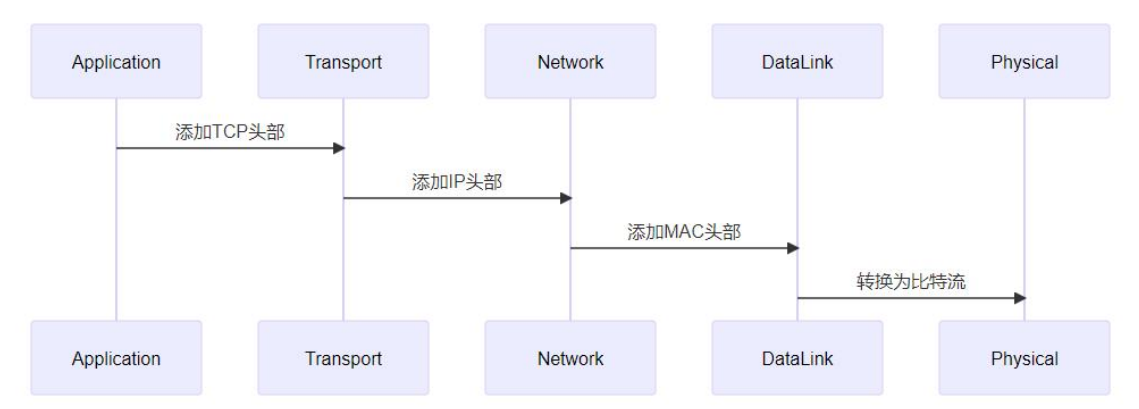
Application layer encapsulation: Application-generated data, such as web page data transmitted by the HTTP protocol and email data transmitted by the SMTP protocol, is called application data at this time. The application layer protocol formats the data according to its own needs. For example, HTTP adds request headers or response headers, containing information such as request method, URL, response status code, etc.
Transport layer encapsulation: Application data reaches the transport layer (such as TCP or UDP). Taking TCP as an example, TCP adds a TCP header to the data, containing information such as source port number, destination port number, sequence number, acknowledgment number, and control bits. The port number is used to identify the application, enabling the receiver to correctly deliver the data to the corresponding application. The UDP header is relatively simple, also having source and destination port numbers, used for multiplexing and demultiplexing. At this point, the data plus the TCP or UDP header is called a segment.
Network layer encapsulation: The transport layer’s segment arrives at the network layer (such as IPv4 or IPv6), which adds an IP header. The IP header contains key information such as the source IP address and destination IP address, used for routing between different networks. The data after adding the IP header is called a packet. For example, when you visit a website, your device encapsulates the TCP segment in an IP packet, with the destination IP address being the website server’s IP.
Data link layer encapsulation: The network layer’s packet arrives at the data link layer (such as Ethernet), which adds a frame header and frame trailer. The Ethernet frame header contains the source MAC address, destination MAC address, etc., and the frame trailer contains a cyclic redundancy check (CRC) value for error detection. The data at this point is called a frame. The frame is converted into electrical or optical signals by the physical layer and transmitted over the physical medium.
De-encapsulation is the reverse process of encapsulation. At the receiving end, data starts from the physical layer and passes upward through each network layer in sequence. Each layer removes the corresponding header information, restoring the data to a form that the application layer can process, as shown in the following figure:
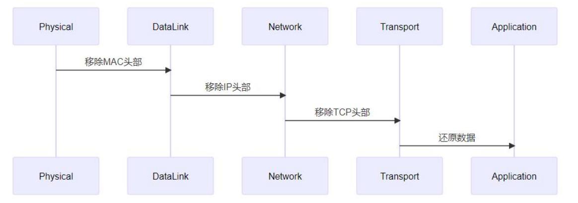
Data link layer de-encapsulation: The physical layer receives electrical or optical signals, converts them into frames, and hands them to the data link layer. The data link layer checks the frame header and trailer, uses CRC verification to ensure error-free data transmission, then removes the frame header and trailer and hands the packet to the network layer.
Network layer de-encapsulation: The network layer receives the packet, checks the IP header, and determines whether it is destined for this host based on the destination IP address. If so, it removes the IP header and hands the segment to the transport layer.
Transport layer de-encapsulation: The transport layer receives the segment, and based on the port number in the TCP or UDP header, delivers the data to the corresponding application, and removes the TCP or UDP header. At this point, the data is restored to application layer data, and the application layer program can process it.
Hardware Connection
RJ45 interface
RJ45 Yes Registered Jack 45 The abbreviation, in computer networks, RJ45 is the short name for the standard 8-core modular interface. RJ45 consists of a plug and a socket, and these two components are connected by a network cable. The RJ45 plug is shown in the following figure:

From an appearance perspective,RJ45 plugis rectangular, with a plastic shell on the outside,and has 8 metal contacts on the inside for electrical connection with the RJ45 socket.。
Corresponding to the RJ45 plug, in the RJ45 socketthere are also 8 metal contact pieces, used to connect with the RJ45 plug.. The 8 metal contacts at the front end of the RJ45 plug will come into close contact with the metal pieces inside the socket when inserted, thereby achieving signal transmission.

Both 100 Mbps Ethernet ports and Gigabit Ethernet ports use RJ45 interfaces for physical connection. However, although they look exactly the same, their transmission capabilities are quite different. The corresponding pin usage is also quite different.
100 Mbps RJ45 interfaceIt has 8 pins, which are:
| Pin number | Label | Chinese name | Description |
|---|---|---|---|
| 1 | TX+ | Transmit Data + | Positive terminal of the Ethernet differential transmit signal |
| 2 | TX- | Transmit Data - | Negative terminal of the Ethernet differential transmit signal |
| 3 | RX+ | Receive Data + | Positive terminal of the Ethernet differential receive signal |
| 4 | NC | Unused pin | No electrical connection, unused |
| 5 | NC | Unused pin | No electrical connection, unused |
| 6 | RX- | Receive Data - | Negative terminal of the Ethernet differential receive signal |
| 7 | NC | Unused pin | No electrical connection, unused |
| 8 | NC | Unused pin | No electrical connection, unused |
Differential signal: TX+/- and RX+/- are paired differential signal lines. Differential transmission provides anti-interference and improves the stability of Ethernet data transmission. This is the core design of the RJ45 network port.
Standard matching: This definition conforms toT568Bthe wiring standard (most commonly used in residential/industrial scenarios), and differs from the T568A standard only in wire order arrangement; the pin functions are identical.
NC Pin Function: Pins 4, 5, 7, and 8 are reserved pins. Some industrial-grade Ethernet ports use them for power supply (e.g., POE power), but in conventional Ethernet applications, they are all NC (no connection).
Gigabit RJ45 InterfaceIt also has 8 pins. Compared with Fast Ethernet, the Gigabit Ethernet port enables all 8 pins, divided into 4 differential pairs to achieve full-duplex high-speed transmission.
| Pin Number | Name | Description | Transmission Direction | Differential Pair Group |
|---|---|---|---|---|
| 1 | TX_D1+ | Transceive Data1+ (transmit signal +) | Send | Pair 1 |
| 2 | TX_D1- | Transceive Data1- (transmit signal -) | Send | Pair 1 |
| 3 | RX_D2+ | Receive Data2+ (receive signal +) | Receive | Pair 2 |
| 4 | BI_D3+ | Bi-directional Data3+ (bidirectional signal) | Bidirectional | Pair 3 |
| 5 | BI_D3- | Bi-directional Data3- (bidirectional signal) | Bidirectional | Pair 3 |
| 6 | RX_D2- | Receive Data2- (receive signal -) | Receive | Pair 2 |
| 7 | BI_D4+ | Bi-directional Data4+ (bidirectional signal) | Bidirectional | Fourth pair |
| 8 | BI_D4- | Bi-directional Data4- (bidirectional signal) | Bidirectional | Fourth pair |
Transmission rate and pin utilization: 100BASE-TX (Fast Ethernet) uses only 4 pins: 1/2 (TX), 3/6 (RX), whileGigabit Ethernet (1000BASE-T) uses all 8 pins, and achieves a 1 Gbps transmission rate by simultaneously transmitting and receiving over 4 differential pairs.
Function of bidirectional pins (BI): Pins 4/5 and 7/8 are designed for bidirectional transmission. In Gigabit mode, these two pairs dynamically switch the transmission/reception direction according to communication needs, and work with digital signal processing (DSP) technology to achieve full-duplex communication.
Differential transmission characteristics: Each pair of pins (e.g., TX_D1+/TX_D1-) are differential signal lines. They transmit signals through the voltage difference between the two wires, which effectively suppresses common-mode interference and improves the stability of high-speed data transmission. This is the core design of the Ethernet physical layer.
Cabling standard compatibility: This pin definition still follows the T568A/T568B cabling standards, and the pinout is consistent with Fast Ethernet ports. Therefore, Gigabit Ethernet cables can be used backward compatibly with Fast Ethernet ports.
MAC controller
The full name of the MAC controller is Media Access Control. It belongs to OSI Layer 2 (data link layer) a part of.
The main function of the MAC controller is to control the connection with the PHY chip. It is like a ‘bridge administrator’, responsible for managing the transmission of data between the data link layer and the physical layer, ensuring that data can flow smoothly between the two layers.
The main functions of the MAC controller include:
- Ethernet frame encapsulation and parsing
- Responsible for adding/parsing the Ethernet frame header (destination MAC, source MAC, type field)
- Checks and generates CRC (FCS)
- Data transmission and reception control
- Read data from system memory (DMA), encapsulate into Ethernet frames and transmit
- Receive data from PHY and write to memory
- Traffic and buffer management
- Transmit/Receive FIFO
- Notify CPU via interrupt or polling
- DMA descriptor management (driver layer focus)
- Link layer control
- Supports full duplex / half duplex
- Supports flow control (PAUSE frames)
- Statistics (packet loss, collisions, error counts, etc.)
- Interface with PHY
- Through the MII / RMII / RGMII / SGMII Communicate with PHY via interfaces
- Through the MDIO/MDC Configure and manage the PHY chip
PHY chip
PHY chip stands for Physical Layer chip. The main task of the PHY chip is toConvert digital signals into analog signals suitable for transmission over physical media (such as network cables), thenConvert received analog signals back into digital signals, so that the computer can recognize and process them.
The core functions of PHY include:
- Signal encoding and decoding
- 100M:MLT-3、4B/5B
- 1000M:PAM-5
- Adaptive equalization, echo cancellation
- Auto-Negotiation
- Negotiate speed (10M / 100M / 1000M)
- Negotiate duplex mode (half duplex / full duplex)
- Link detection
- Ethernet cable plug/unplug detection
- Report Link Up / Link Down status to MAC
- Clock recovery and synchronization
- Recover clock from received signal
- Ensure accurate data sampling
- Management interface to the MAC
- use MDIO/MDC Register interface
- Common in Linux drivers
phy_read()/phy_write()
Network transformer
Network transformer, also known as network isolation transformer or Ethernet transformer, mainly functions for signal coupling, electrical isolation, and impedance matching. It is located between the PHY and the RJ45 connector, and is a passive component.
The main functions of the network transformer include:
- Electrical isolation
- Provide isolation capability above 1500V
- Prevent surges and potential differences from damaging the chip
- Meet Ethernet safety standards (e.g., IEEE 802.3)
- Signal coupling
- Couple the differential signal output from the PHY to the twisted pair
- Block DC component and transmit only AC signals
- Impedance matching
- Match the PHY output impedance to the cable (100Ω)
- Reduce reflections and improve signal quality
- EMI suppression
- Cooperate with common-mode inductors to reduce electromagnetic interference
- Improve anti-interference capability
Many RJ45 connectors internally integrate network transformers and common-mode inductors, often referred to in engineering as “RJ45 port with LEDs”。
Connection Methods
Depending on the integration of the CPU, MAC, and PHY, it can be further divided into the following three methods:
Method 1: The CPU integrates MAC and PHY internally
In this method, the CPU integrates the MAC and PHY into itself. Although this method can reduce the number of peripheral components, the CPU cost increases significantly, and because everything is integrated inside the CPU, flexibility is poor. Therefore, this method is rarely used in practical applications.
Method 2: The CPU integrates the MAC internally, and the PHY uses a separate chip
The CPU only integrates the MAC controller, and the PHY uses an independent chip. The advantage of this method is that the PHY chip can be flexibly selected according to the application scenario, and it is alsocurrently the mainstream method。

The iTOP-RK3568 also uses this method. It should be noted that the RJ45 socket on the iTOP-RK3568 development board has an integrated network transformer. If the
RJ45 socket does not have an integrated network transformer, then a separate network transformer chip is required.
Method 3: The CPU does not integrate MAC and PHY; MAC and PHY use separate chips or integrated chips
In this connection mode, the CPU does not have MAC and PHY functions, which is what we often call the CPU itself does not support network functions. If network functions are needed, they must be adapted through other interfaces. Therefore, this method has higher cost.

PHY Interface
In embedded network development, the most mainstream solution is shown in the following figure:
From the block diagram, the left side of the PHY chip connects to the MAC, and the right side connects to the RJ45 socket. It can be seen that the PHY chip plays a bridging role.
The PHY chip can be connected to the MAC controller through MII, RMII, GMII, RGMII, and MDIO interfaces.
MII Interface
The full name of the MII interface is Media Independent Interface, i.e., the Media Independent Interface.
The MII interface has a transfer rate of 10 Mbps or 100 Mbps; the clock is 25 MHz at 100 Mbps and 2.5 MHz at 10 Mbps. The hardware connection is shown in the figure below:

The MII interface requires a total of 16 signal lines, whose meanings are as follows:
| Signal Line Type | Signal line name | Number | Description | Direction (MAC←→PHY) | Core function |
|---|---|---|---|---|---|
| Transmit Channel | TX_CLK | 1 | Transmit clock, generated by the PHY | MAC ← PHY | Synchronous clock for transmitted data (25 MHz at 100 Mbps) |
| TX_EN | 1 | Transmit enable, active high | MAC → PHY | Indicates that data on TXD[3:0] is valid | |
| TXD[3:0] | 4 | Transmit data bus | MAC → PHY | Ethernet data sent in parallel (4 bits wide) | |
| TX_ER | 1 | Transmit error, active high | MAC → PHY | Indicates that an error occurred during transmission (e.g., frame format error) | |
| Receive Channel | RX_CLK | 1 | Receive clock, generated by the PHY | MAC ← PHY | Synchronous clock for received data (25 MHz at 100 Mbps) |
| RX_DV | 1 | Receive data valid, active high | MAC ← PHY | Indicates that data on RXD[3:0] is valid (replaces RX_EN) | |
| RXD[3:0] | 4 | Receive Data Bus | MAC ← PHY | Ethernet data received in parallel (4 bits wide) | |
| RX_ER | 1 | Receive error, active high | MAC ← PHY | Indicates that an error occurred during reception (e.g., CRC error, frame too long) | |
| Collision / Carrier Sense | COL | 1 | Collision detection, active high | MAC ← PHY | In half-duplex mode, indicates a data collision on the bus |
| CRS | 1 | Carrier sense, active high | MAC ← PHY | In half-duplex mode, indicates that the bus is busy |
RMII interface
The full name of the RMII interface is Reduced Media Independent Interface, namely ‘Reduced Media Independent Interface’, which is a simplified version of the MII interface. Therefore, compared with the MII interface, the RMII interface reduces the number of signal lines for data transmission and reception by half. The hardware connection is shown in the following figure:

The RMII interface requires a total of 7 signal lines, with the following meanings:
| Signal line name | Number | Direction (MAC ↔ PHY) | Core description & key development points |
|---|---|---|---|
| REF_CLK | 1 line | External → MAC + PHY | 50 MHz fixed reference clock,the only synchronous clock for transmitting and receiving data(replaces MII’s TX_CLK/RX_CLK); it must be supplied to both MAC and PHY, and the clock source can be the PHY’s built-in crystal oscillator or an external crystal oscillator. |
| TX_EN | 1 line | MAC → PHY | Transmit enable, active high; the PHY samples the TXD [1:0] data only when this signal is high |
| TXD[1:0] | 2 lines | MAC → PHY | 2-bit parallel transmit data bus; achieves 100 Mbps rate through ‘2-bit width × 50 MHz’, which is the core design of RMII simplification |
| CRS_DV | 1 line | PHY → MAC | Multiplexed signal: Full-duplex mode: only as ‘RX_DV (Receive Data Valid)’ Half-duplex mode: simultaneously indicates ‘CRS (Carrier Sense)’ and ‘DV (Data Valid)’ |
| RXD[1:0] | 2 lines | PHY → MAC | 2-bit parallel receive data bus; MAC samples data only when CRS_DV is high |
GMII interface
The full name of the GMII interface is Gigabit Media Independent Interface, i.e., ‘Gigabit Media Independent Interface’. It is an interface designed to meet the high-speed data transmission requirements of Gigabit Ethernet. The clocks are 2.5M, 25M, and 125M at 10M/100M/1000M respectively. The hardware connection is shown in the following figure:

The GMII interface requires a total of 25 signal lines, with meanings as follows
| Signal Name | Width / Quantity | Chinese Description | Signal Direction | Function Details (Development Core) | Rate Adaptation Description |
|---|---|---|---|---|---|
| GTX_CLK | 1 line | Gigabit transmit clock | MAC → PHY | Dedicated transmit synchronization clock for Gigabit mode, fixed125MHz, MAC transmits data based on this clock, and PHY samples TXD data synchronously. | Used only in Gigabit (1000M) mode, core clock |
| TX_CLK | 1 line | 100M transmit clock | MAC → PHY | Transmit clock compatible with 10/100M rates, 10M=2.5MHz, 100M=25MHz | Used only in 10/100M mode, invalid in Gigabit mode (floating) |
| TXD[7:0] | 8 lines | Transmit data bus | MAC → PHY | 8-bit parallel transmit data, the core wide bus design of GMII | Fully compatible with Gigabit / Fast Ethernet / 10M Ethernet, different rates use different clocks |
| TX_EN | 1 line | Transmit Enable | MAC → PHY | Active high, indicates data on TXD[7:0] is valid; PHY samples data only at this time | universal across all rates |
| TX_ER | 1 line | Transmit Error Indication | MAC → PHY | Active high, indicates the current transmitted data frame has a format error | universal across all rates |
| RX_CLK | 1 line | Receive Clock | PHY → MAC | Receive synchronous clock: Gigabit mode = 125MHz, Fast Ethernet = 25MHz, 10M Ethernet = 2.5MHz,extracted and provided by the PHY from the received data, MAC synchronously samples RXD data | Common to all rates, core receive clock |
| RXD[7:0] | 8 lines | Receive Data Bus | PHY → MAC | 8-bit parallel receive data, the core wide bus design of GMII | Fully compatible with Gigabit / Fast Ethernet / 10M Ethernet |
| RX_DV | 1 line | Receive Data Valid | PHY → MAC | Active high, indicates data on RXD[7:0] is valid; MAC samples data only at this time | Common to all rates, replaces the RX_EN naming of MII |
| RX_ER | 1 line | Receive error indication | PHY → MAC | Active high; indicates that the currently received data frame has errors (CRC/FCS error, frame length error, etc.) | universal across all rates |
| CRS | 1 line | Carrier sense signal | PHY → MAC | OnlyHalf-duplex modeActive high; high level indicates the Ethernet bus is busy, prohibiting the MAC from sending data. | Common to all rates; this signal is inactive (pulled low) in full-duplex mode. |
| COL | 1 line | Collision detection signal | PHY → MAC | OnlyHalf-duplex modeActive high; high level indicates a data collision on the bus, and the MAC triggers frame retransmission. | Common to all rates; no collision occurs in full-duplex mode, so this signal is inactive. |
RGMII interface
RGMII is a simplified version of GMII. It reduces the pin count from 25 in GMII to 14 in RGMII. At 10M/100M/1000M, the clocks are 2.5 MHz, 25 MHz, and 125 MHz, respectively. The hardware connection is shown in the figure below:

The RGMII interface requires a total of 14 signal lines, with meanings as follows:
| Signal Name | Number | Direction (MAC ↔ PHY) | Core description & key development points | Rate adaptation |
|---|---|---|---|---|
| TXC | 1 line | MAC → PHY | Transmit clock, fixed in gigabit mode125MHz;dual-edge sampling(Rising edge + falling edge) is the core of RGMII’s simplification. | 1000M=125MHz100M=25MHz10M=2.5MHz |
| TX_CTL | 1 line | MAC → PHY | Transmit control signal,multiplexes TX_EN (transmit enable) and TX_ER (transmit error); synchronized with both edges of TXC | universal across all rates |
| TXD[3:0] | 4 lines | MAC → PHY | Transmit data bus, 4-bit parallel;dual-edge sampling, each clock edge transfers 1 bit of data, equivalent to 8-bit bandwidth | universal across all rates |
| RXC | 1 line | PHY → MAC | Receive clock, fixed in gigabit mode125MHz; provided by the PHY, also supportsdual-edge sampling | 1000M=125MHz100M=25MHz10M=2.5MHz |
| RX_CTL | 1 line | PHY → MAC | Receive control signal,multiplexes RX_DV (receive valid) and RX_ER (receive error); synchronized with both edges of RXC | universal across all rates |
| RXD[3:0] | 4 lines | MAC → PHY | Receive data bus, 4-bit parallel;dual-edge sampling, equivalent to 8-bit bandwidth | universal across all rates |
MDIO interface
The full name of the MDIO interface is Management Data Input/Output, which is the Management Data Input/Output interface.
Its main function isto enable the MAC controller to manage and control the PHY chip, for example, configuring the working rate by setting PHY registers through the MDIO interface; it can also obtain the status of the Ethernet port by reading the status registers of the PHY chip.
The MDIO interface is asynchronous serial half-duplex interface, consisting of two signal lines, namely:
- MDIO: acts as the data line, used to transmit configuration and management data between the MAC layer and the PHY layer.
- MDC: acts as the clock line, providing clock synchronization for data transmission.
Example
RTL8211 PHY chip
The iTOP-RK3568 development board uses the RTL8211 PHY chip. The RTL8211 supports transmission rates of 10Mbps, 100Mbps, and 1000Mbps, and has auto-negotiation capability, which can automatically adjust the working mode according to the network environment.
From the circuit connection diagram in the RTL8211 chip datasheet, it can be seen that the RTL8211 chip connects to the RJ45 interface through the MDI interface. The MAC controller connects to the PHY chip through the RGMII interface and the MDIO interface. As shown in the figure below:

Simplify the block diagram in the datasheet:

The iTOP-RK3568 core board has an RGMII interface brought out. As shown in the figure below:

The iTOP-RK3568 core board is connected to the RTL8211 chip through the RGMII interface and the MDIO interface. The schematic is as follows

- Pins 15, 16, 17, and 18 correspond to TXD3, TXD2, TXD1, and TXD0 respectively. They are transmit pins, with the direction from MAC to PHY.
- Pins 22, 23, 24, 25, and 26 correspond to RXD3, RXD2, RXD1, and RXD0 respectively. They are receive pins, with the direction from PHY to MAC.
- Pin 20 is the TXC pin, the transmit clock signal pin.
- Pin 27 is the RXC pin, the receive clock signal pin.
- Pin 26 is the RXCTL pin, the receive control signal pin.
- Pins 13 and 14 are the MDIO pins.
- Pin 31 is the INTB/PMEB pin. If these two functions are not used, this pin is left floating. If Page 0xd40, REG.22 bit[5] register is set to 1, it is the PMEB function; if set to 0, it is the interrupt function.
The RTL8211 is connected to the RJ45 socket via the MDI interface, as shown in the schematic below:

Among them, pins 1 to 10 correspond to the MDIP0, MDIN0, MDIP1, MDIN1, MDIP2, MDIN2, MDIP3, and MDIN3 pins of the MDI interface respectively.
The MDI interface is used to connect the PHY chip to the network transformer, or in other words, to the RJ45 socket.

PHY registers
In the 802.3 specification, the first 16 registers of the PHY chip are defined. As shown in the figure below:

In development, the registers we deal with the most are register 0 and register 1.
Register 0 is the control register: It is used to configure the operating mode and parameters of the PHY chip. Through the control register, you can set the chip’s transmission rate (10Mbps, 100Mbps, or 1000Mbps), duplex mode (full-duplex or half-duplex), and enable or disable the auto-negotiation function, etc.
Register 1 is the status register: It is used to indicate the current working status of the PHY chip. For example, through the status register, you can check whether the connection to the network has been successfully established, whether a link fault is detected, the current transmission rate and duplex mode, and other information.
Registers 16 to 31 are extended registers: Registers 0 to 15 are defined by IEEE 802.3. Regardless of which manufacturer’s PHY chip is used, registers 0 to 15 are exactly the same. Therefore, in general, the generic PHY driver in Linux can be used to drive the PHY chip. However, PHY chips from different manufacturers may have additional feature functions, so the extended registers are registers for PHY manufacturers to use freely. In other words, only when these feature functions are used will the extended registers be involved.
PHY address
Each PHY register has a unique address. Through these addresses, we can accurately access and operate the corresponding registers. On the iTOP-RK3568 development board, the address of the RTL8211 PHY chip can be set through pins 22, 27, and 26.

Physical address (MAC address)
The physical address, also known as the MAC address, is a unique identifier for a network device. It consists of 48 binary bits and is usually represented as 12 hexadecimal digits, such as 00:11:22:33:44:55.
IP address
The IP address is an address at the network layer, used to identify the logical location of a device in the network. It is divided into two versions: IPv4 and IPv6:
- An IPv4 address consists of 32 binary bits and is usually expressed in dotted decimal notation, such as 192.168.1.1;
- An IPv6 address consists of 128 binary bits. The main function of an IP address is to enable communication between different networks. Through IP addresses, data packets can be routed from the source network to the destination network.
PHY address
The PHY address is an address used to uniquely identify a PHY chip within a network. In a system, multiple PHY chips may exist simultaneously. The PHY address allows different PHY chips to be distinguished so that they can be individually configured and managed.
Determining the PHY Chip Address
Taking the Forlinx iTOP-RK3568 development board as an example, the address of its RTL8211 PHY chip is determined in the following way.
Open the datasheet of the RTL8211 PHY chip. As shown in the figure below, pins 22, 26, and 27 are used to configure the PHY chip address.

Also, on the RK3568 baseboard schematic, the three pins of the PHY chip are connected as follows:
From the figure above, the address of the PHY chip is 001, which is 1. The PHY chip sets its address through hardware pins.
Accessing PHY Registers
First, open the debug serial port of the iTOP-RK3568 development board, then power on the board. After entering the terminal, execute the commandcd /sys/bus/mdio_bus/devices, to enter the development board’smdio_busbus device directory.
Then, execute the commandcd stmmac-0:00/, to enter the device of network card 0. The specific operation process is as follows:
1234567 | cd /sys/bus/mdio_bus/devicescd stmmac-0:00/# View the values of the registerscat phy_registers# Modify the value of register 0 and set it to 0x40echo 0x00 0x40 > phy_registers |
Network Application Programming Basics
Endianness
Little-endian mode: The low-order byte is stored at the low address, and the high-order byte is stored at the high address.
Big-endian mode: The high-order byte is stored at the low address, and the low-order byte is stored at the high address.
Byte Order Conversion Functions
There are four common byte order conversion functions: htonl, htons, ntohl, and ntohs. A brief introduction to each function is shown in the table below:
Their core purpose is to resolve the byte order incompatibility between different hosts and the network.
| Function Name | Function description | Data Type | Conversion Direction |
|---|---|---|---|
htonl | Convert 32-bit host byte order to network byte order | uint32_t | Host → Network |
htons | Convert 16-bit host byte order to network byte order | uint16_t | Host → Network |
ntohl | Convert 32-bit network byte order to host byte order | uint32_t | Network → Host |
ntohs | Convert 16-bit network byte order to host byte order | uint16_t | Network → Host |
uint32_t htonl(uint32_t hostlong)
- Function: Used to convert a locally stored 32-bit integer into a format suitable for transmission over the network (big-endian mode).
- Parameter: 32-bit host byte order integer.
- Return value: Returns a 32-bit network byte order integer.
uint16_t htons(uint16_t hostshort)
- Function: Used to convert a locally stored 16-bit integer (such as a port number) into a format suitable for transmission over the network.
- Parameter: 16-bit host byte order integer.
- Return value: Returns a 16-bit network byte order integer.
uint32_t ntohl(uint32_t netlong)
- Function: Used to convert 32-bit data received from the network (such as an IPv4 address) into a format that the local system can process.
- Parameter: 32-bit network byte order integer.
- Return value: Returns a 32-bit host byte order integer.
uint16_t ntohs(uint16_t netshort)
- Function: Used to convert 16-bit data received from the network (such as a port number) into a format that the local system can process.
- Parameter: 16-bit network byte order integer.
- Return value: Returns a 16-bit host byte order integer.
For example, when writing TCP and UDP code, you need to use port numbers, such as 8080. At this point, byte order conversion is required. You need to use htons to convert 8080 from host byte order to network byte order. A simple example program is as follows:
12345678910 | int main(void){ uint16_t host_port = 8080; // Host port number uint16_t net_port = htons(host_port); // Convert to network byte order printf("Host Port: 0x%04X\n", host_port); printf("Network Port: 0x%04X\n", net_port); return 0;} |
Address conversion functions
In addition to byte order conversion, IP addresses also need to be converted. IP addresses are usually displayed in a human-readable form such as dotted decimal (e.g., 192.168.1.1), but inside a program they need to be stored and processed in binary form.
In network programming, there are two IP address conversion functions, namelyinet_ptonandinet_ntopThey support the conversion of IPv4 and IPv6 addresses. A brief introduction to the two functions is as follows:
This table shows two core functions used for IP address format conversion in network programming, which support conversion of both IPv4 and IPv6 addresses.
| Function Name | Function description | Conversion Direction |
|---|---|---|
inet_pton | Converts a string-format IP address in dotted decimal (IPv4) or colon hexadecimal (IPv6) to binary data in network byte order. | String → Binary |
inet_ntop | Converts a binary IP address in network byte order to a string format in dotted decimal (IPv4) or colon hexadecimal (IPv6). | Binary → String |
inet_pton()
- Converts a string address to binary data.
- Converts an IP address string in dotted decimal (IPv4) or colon hexadecimal (IPv6) to binary data in network byte order.
inet_ptonThe function prototype is as follows. It returns 1 on success, 0 if the src format is invalid, and -1 if af is not supported.
1 | int inet_pton(int af, const char *src, void *dst); |
The specific parameter descriptions are as follows:
| Parameter Name | Description | Data Type / Value Range | Example values |
|---|---|---|---|
af | Specifies the address family to distinguish between IPv4 and IPv6 addresses. | AF_INET:IPv4AF_INET6:IPv6 | AF_INET(IPv4) |
src | Pointer to the IP address string to be converted. | string | "192.168.1.1" |
dst | Pointer to the buffer that stores the converted binary data. | binary data | struct in_addr |
Example:
12345678910111213141516 | int main(){ const char *ipv4 = "192.168.1.1"; struct in_addr addr; if (inet_pton(AF_INET, ipv4, &addr) <= 0) { printf("Invalid IPv4 address\n"); } else { printf("Network byte order: 0x%x\n", addr.s_addr); } return 0;} |
inet_ntop()
- Converts binary data to a string address.
inet_ntopThe function is used to convert a binary IP address in network byte order to a human-readable string form (dotted decimal or colon hexadecimal).
inet_ntopThe function prototype is as follows. On success, it returns a pointer to dst; on failure, it returns NULL and sets errno.
1 | const char *inet_ntop(int af, const void *src, char *dst, socklen_t size); |
The parameters are as follows:
| Parameter Name | Description | Data Type / Value Range | Example values |
|---|---|---|---|
af | Specifies the address family to distinguish between IPv4 and IPv6 addresses. | AF_INET:IPv4AF_INET6:IPv6 | AF_INET(IPv4) |
src | Pointer to the buffer that stores the binary IP address. | binary data | struct in_addr |
dst | Pointer to a buffer that stores the converted string form of the IP address. | string | char ip[INET_ADDRSTRLEN] |
size | dstThe size of the buffer, ensuring it is large enough to accommodate the result string. | socklen_t | INET_ADDRSTRLENorINET6_ADDRSTRLEN |
Example code:
12345678910111213141516 | int main(){ struct in_addr addr; addr.s_addr = 0xC0A80101; // 192.168.1.1 in network byte order char ip[INET_ADDRSTRLEN]; if (inet_ntop(AF_INET, &addr, ip, sizeof(ip)) == NULL) { printf("inet_ntop"); } else { printf("Dotted decimal: %s\n", ip); } return 0;} |
UDP
The full English name of UDP is User Datagram Protocol, meaning User Datagram Protocol, it is aNo connectionThe transport layer protocol, part of the TCP/IP protocol stack. It provides a simple, lightweight data transmission method, suitable for scenarios that require high speed but low reliability, such as video conferencing, online games, voice calls, etc. These scenarios are sensitive to latency and can tolerate occasional packet loss.

UDP Functions
| function name | Function description | Use case |
|---|---|---|
socket() | Create a socket as an endpoint for network communication. | Both the server and client need to call this function to create a handle for subsequent communication. |
bind() | Bind the socket to the specified IP address and port number, so that the system can deliver data sent to that address to this socket. | The server must call it to bind a fixed listening port so that clients can find it; clients usually do not need to call it explicitly. |
sendto() | Sends a datagram to the specified destination IP address and port; it is the core sending interface of the UDP protocol. | The client uses it to send requests to the server; the server uses it to send responses to the client. |
recvfrom() | Receive a datagram from the network and obtain the sender’s IP address and port information. | The server uses it to receive requests from the client; the client uses it to receive responses from the server. |
sendto()
sendto()is a system call used for sending data, mainly for the connectionless UDP protocol. It allows a program to send data to a specified destination address (i.e., destination IP and port). Andsend()Different,sendto()The destination address needs to be explicitly specified, making it very suitable for connectionless communication. Its function prototype is as follows:
1 | ssize_t sendto(int sockfd, const void *buf, size_t len, int flags, const struct sockaddr *dest_addr, socklen_t addrlen); |
Parameters:
| Parameter name | Type | Description |
|---|---|---|
sockfd | int | Socket file descriptor, bysocket()Function creation is the handle for all subsequent network operations. |
buf | const void * | Pointer to the data buffer to be sent, which isconsttype, indicating that the function will not modify the contents of the buffer. |
len | size_t | The length of the data buffer, in bytes, telling the function how many bytes of data to send. |
flags | int | Send flags, usually set to0. Special flags can be set (such asMSG_DONTROUTEmeaning do not consult the routing table,MSG_CONFIRMused for link-layer acknowledgment), but rarely used in regular UDP communication. |
dest_addr | struct sockaddr * | Pointer to the destination address structure, usuallystruct sockaddr_in(IPv4) orstruct sockaddr_in6(IPv6), containing the destination IP and port information. |
addrlen | socklen_t | The size of the destination address structure, in bytes, used to tell the functiondest_addrhow large the structure it points to is. |
On success, it returns the actual number of bytes sent.
recvfrom()
recvfrom()is a system call for receiving data, mainly used for the connectionless UDP protocol. It allows a program to receive data packets from a specified source address (i.e., the sender’s IP and port). Unlikerecv()Different,recvfrom()it can obtain the sender’s address information, making it very suitable for connectionless communication. Its function prototype is as follows:
1 | ssize_t recvfrom(int sockfd, void *buf, size_t len, int flags, struct sockaddr *src_addr, socklen_t *addrlen); |
The parameters of this function are described as follows:
| Parameter name | Type | Description |
|---|---|---|
sockfd | int | Socket file descriptor, bysocket()function, and is the handle for network operations. |
buf | void * | Pointer to the buffer that stores the received data; the function writes the received data into this buffer. |
len | size_t | The maximum length of the buffer (in bytes). If the received data exceeds this length, the excess will be truncated. |
flags | int | Receive flags, usually set to0. Special flags can be set (such asMSG_PEEKonly peek at data without removing it,MSG_DONTWAITnon-blocking reception), rarely used in regular UDP communication. |
src_addr | struct sockaddr * | Pointer to the structure that stores the sender’s address, usuallystruct sockaddr_in(IPv4) orstruct sockaddr_in6(IPv6), used to obtain the sender’s IP and port. |
addrlen | socklen_t * | Pointer to the size of the sender address structure. Before calling, it must be initialized to the expected size of the structure; after calling, it will be updated to the actual address length. |
On success, it returns the actual number of bytes received.
example
udp_client.c
123456789101112131415161718192021222324252627282930313233343536373839404142434445464748495051525354555657585960616263646566676869 | int main(int argc, char *argv[]) { // Define variable port to store the port number. int port; // Define variable fd to store the socket descriptor. int fd; // Define character array buf as the buffer for sending data. char buf[1024]; // Check whether the number of command-line arguments is 3. if (argc != 3) { // If the number of arguments is incorrect, output usage example prompt information. printf("for example: ./app ip port\n"); // Return -1 to indicate abnormal program termination return -1; } // Convert the port number string in the command-line argument to an integer. port = atoi(argv[2]); // Create a UDP socket. // AF_INET indicates using the IPv4 protocol. // SOCK_DGRAM indicates this is a UDP socket. // 0 indicates using the default protocol. fd = socket(AF_INET, SOCK_DGRAM, 0); // Check whether the socket was created successfully. if (fd == -1) { // If creation fails, output an error message. printf("socket fd error\n"); // Return -1 to indicate abnormal program termination return -1; } // Initialize a sockaddr_in structure to store the destination server address information. struct sockaddr_in addr = {0}; // Set the address family to IPv4. addr.sin_family = AF_INET; // Convert the port number from host byte order to network byte order and assign it to addr.sin_port. addr.sin_port = htons(port); // Convert the IP address string from the command-line argument to an IP address in network byte order and assign it to addr.sin._addr.s_addr // Here you can also use inet_pton(AF_INET, argv[1], &addr.sin_addr);, but the current code uses inet_addr is also feasible addr.sin_addr.s_addr = inet_addr(argv[1]); // Clear the buffer buf to zero to prepare for subsequent data reception memset(buf, 0, sizeof(buf)); // Enter an infinite loop to continuously send data to the server. while (1) { // Read a string from standard input into the buf buffer. scanf("%s", buf); // Send the data in buf to the server via the UDP socket // fd is the socket descriptor. // buf is the data to be sent // strlen(buf) is the length of the data // 0 indicates the default sending flag // (struct sockaddr*)&addr is the server address // sizeof(addr) is the size of the server address structure. sendto(fd, buf, strlen(buf), 0, (struct sockaddr*)&addr, sizeof(addr)); // Clear the buf buffer to zero to prepare for the next data reception memset(buf, 0, sizeof(buf)); } return 0;} |
udp_server.c
123456789101112131415161718192021222324252627282930313233343536373839404142434445464748495051525354555657585960616263646566676869707172737475767778798081828384858687888990 | int main(int argc, char *argv[]) { // Define variable port to store the port number. int port; // Define variable fd to store the socket descriptor. int fd; // Define a character array buf as the buffer for receiving data char buf[1024]; // Define a variable ret to store the function return value int ret; // Define a variable len to store the length of the address structure int len; // Check whether the number of command-line arguments is 3. if (argc != 3) { // If the number of arguments is incorrect, output a usage example prompt printf("for example: ./app ip port\n"); // Return -1 to indicate abnormal program termination return -1; } // Convert the port number string in the command-line argument to an integer. port = atoi(argv[2]); // Create a UDP socket. // AF_INET indicates the use of the IPv4 protocol // SOCK_DGRAM indicates that this is a UDP socket // 0 indicates using the default protocol fd = socket(AF_INET, SOCK_DGRAM, 0); // Check whether the socket was created successfully. if (fd == -1) { // If creation fails, output an error message. printf("socket fd error\n"); // Return -1 to indicate abnormal program termination return -1; } // Initialize local address structure local_addr struct sockaddr_in local_addr = {0}; // Initialize source address structure src_addr struct sockaddr_in src_addr = {0}; // Set the address family of the local address to IPv4 local_addr.sin_family = AF_INET; // Convert the port number from host byte order to network byte order and assign it to local._addr.sin_port local_addr.sin_port = htons(port); // Convert the IP address string from command-line arguments to an IP address in network byte order and assign it to local._addr.sin_addr.s_addr local_addr.sin_addr.s_addr = inet_addr(argv[1]); // Bind socket fd to local_addr ret = bind(fd, (struct sockaddr *)&local_addr, sizeof(local_addr)); // Check whether the binding is successful if (ret == -1) { // If binding fails, output an error message printf("bind error\n"); // Return -1 to indicate abnormal program termination return -1; } // Set the length of the src_addr structure len = sizeof(src_addr); // Clear the buffer buf to prepare for receiving data memset(buf, 0, sizeof(buf)); // Enter an infinite loop to continuously receive data while (1) { // Receive data from UDP socket fd // buf is the buffer for receiving data // sizeof(buf) is the buffer size // 0 is the receiving flag // (struct sockaddr *)&src_addr is a pointer to the source address structure // &len is used to return the actual length of the source address structure recvfrom(fd, buf, sizeof(buf), 0, (struct sockaddr *)&src_addr, &len); // Convert the source IP address to dotted decimal format and output it // The inet_ntoa function converts an IP address in network byte order to a dotted decimal string // The ntohs function converts a port number in network byte order to host byte order printf("ip:%s port:%d\n", inet_ntoa(src_addr.sin_addr), ntohs(src_addr.sin_port)); // Output the received data printf("buf is %s\n", buf); // Clear the buffer buf to prepare for the next reception memset(buf, 0, sizeof(buf)); } return 0;} |
TCP
The full English name of TCP is Transmission Control ProtocolTransmission Control Protocol, meaning ‘transmission control protocol’, and it is aconnection-orientedtransport layer protocol, and like UDP, it belongs to the core part of the TCP/IP protocol stack.
TCP ensures the integrity, order, and losslessness of data during transmission by establishing a reliable end-to-end connection. It uses a three-way handshake to establish connections, and guarantees the reliability of data transmission through functions such as acknowledgment mechanisms, retransmission mechanisms, and flow control.
Therefore, TCP is suitable for scenarios with high requirements for data accuracy, such as file transfer, email, and web browsing, where data integrity and ordering are crucial, and there is relatively high tolerance for latency.

- Compared with the UDP client, the TCP client has an additional step of calling connect to initiate a connection request.
- Compared with the UDP server, the TCP server has two additional steps: calling listen to start listening mode, and calling accept to block and wait for client requests.
- listen sets the socket to passive mode to wait for client connection requests.
- When a client initiates a connection, accept blocks and waits until it receives a request, then returns a new socket file descriptor, which is dedicated to communicating with that client.
After the client initiates a connection request via connect, it performs a TCP three-way handshake with the server to establish a connection. Once the connection is established, the client and server can send and receive data using write() and read().
After data transmission is complete, the client and server each close the connection via close().
TCP functions
connect()
connect() is a system call used to establish a connection, mainly on the client side. It initiates a connection request to the server by specifying the server’s address (IP address and port number). For TCP, connect() triggers the TCP three-way handshake process. Note that for UDP, connect can also be used, but it does not actually establish a connection; instead, it binds the destination address to the socket for subsequent communication. Its function prototype is as follows:
1 | int connect(int sockfd, const struct sockaddr *addr, socklen_t addrlen); |
Returns 0 on success, and -1 on failure.
| Parameter name | Type | Description |
|---|---|---|
sockfd | int | Socket file descriptor, bysocket()Function creation is the handle for all subsequent network operations. |
addr | struct sockaddr * | Pointer to the destination address structure, usuallystruct sockaddr_in(IPv4) orstruct sockaddr_in6(IPv6), containing the IP address and port number to be bound. |
addrlen | socklen_t | The size of the destination address structure, in bytes, for examplesizeof(struct sockaddr_in)。 |
listen()
listen()is a system call used to set a socket to listening mode, mainly for TCP servers. It converts the socket from active mode (for initiating connections) to passive mode (for receiving connection requests).listen()After calling it, the socket starts listening for connection requests from clients and maintains a waiting queue to manage these requests. Its function prototype is as follows
1 | int listen(int sockfd, int backlog); |
| Parameter name | Type | Description |
|---|---|---|
sockfd | int | Socket file descriptor, bysocket()created and passedbind()Bind to a specific address and port. |
backlog | int | The maximum length of the waiting connection queue, representing the number of TCP connection requests that can be queued for processing at the same time. |
Returns 0 on success, and -1 on failure.
accept()
accept()is a system call used to accept client connection requests, mainly used for TCP servers. It takes a connection request from the listening socket’s waiting queue and creates a new socket specifically for communicating with that client. In this way,accept()the server can handle connection requests from multiple clients. Its function prototype is as follows:
1 | int accept(int sockfd, struct sockaddr *addr, socklen_t *addrlen); |
The parameters of this function are described as follows:
| Parameter name | Type | Description |
|---|---|---|
sockfd | int | Listening socket file descriptor, created bysocket()created and passedlisten()set to listening mode. |
addr | struct sockaddr * | Pointer to a structure storing the client address (such asstruct sockaddr_inrepresenting an IPv4 address). It can beNULLindicating that the client address does not need to be obtained. |
addrlen | socklen_t * | Pointer to the size of the client address structure. Before the call, it should be initialized to the size of the target address structure; after the call, it will be updated to the actual address length. |
Returns a new socket file descriptor on success, and -1 on failure.
example
tcp_client.c
12345678910111213141516171819202122232425262728293031323334353637383940414243444546474849505152535455565758596061626364656667686970717273747576777879808182 | int main(int argc, char *argv[]) { // Define a variable port to store the port number obtained from the command line. int port; // Define a variable fd to store the socket descriptor. int fd; // Define a character array buf as a data buffer to store data read from standard input and received data. char buf[1024]; // Define a variable ret to store the return value of the function. int ret; // Check whether the number of command-line arguments is 3. if (argc != 3) { // If the number of arguments is incorrect, output usage example prompt information. printf("for example: ./app ip port\n"); // Return -1, indicating abnormal program termination return -1; } // Convert the port number string in the command-line argument to an integer. port = atoi(argv[2]); // Create a TCP socket. // AF_INET indicates using the IPv4 protocol. // SOCK_STREAM indicates this is a connection-oriented byte-stream socket, suitable for the TCP protocol. // 0 indicates using the default protocol. fd = socket(AF_INET, SOCK_STREAM, 0); // Check whether the socket was created successfully. if (fd == -1) { // If creation fails, output an error message. printf("socket fd error\n"); // Return -1, indicating abnormal program termination return -1; } // Initialize a sockaddr_in structure to store the server's address information. struct sockaddr_in addr = {0}; // Set the address family to IPv4. addr.sin_family = AF_INET; // Convert the port number from host byte order to network byte order and assign it to addr.sin_port. addr.sin_port = htons(port); // Convert the IP address string from the command-line argument to an IP address in network byte order and assign it to addr.sin._addr.s_addr // Here you can also use inet_pton(AF_INET, argv[1], &addr.sin_addr);, but the current code uses inet_addr is also feasible addr.sin_addr.s_addr = inet_addr(argv[1]); // Use the connect function to connect to the server. // fd is the socket descriptor. // (struct sockaddr*)&addr is a pointer to the server address structure. // sizeof(addr) is the size of the server address structure. ret = connect(fd, (struct sockaddr*)&addr, sizeof(addr)); // Check whether the connection is successful. if (ret < 0) { // If the connection fails, output an error message. printf("connect error\n"); // Return -1, indicating abnormal program termination return -1; } // Clear the buffer buf to zero, preparing for subsequent operations. memset(buf, 0, sizeof(buf)); // Enter an infinite loop to continuously send data to the server. while (1) { // Read a string from standard input into the buf buffer. scanf("%s", buf); // Send the data in buf to the server through the TCP socket. // Note: Using the sendto function here is not appropriate for TCP sockets; TCP usually uses the send function. // The correct one should be send(fd, buf, strlen(buf), 0); // But the original code uses sendto; here we comment according to the original code logic. sendto(fd, buf, strlen(buf), 0, (struct sockaddr*)&addr, sizeof(addr)); // Clear the buf buffer to zero to prepare for the next data reception memset(buf, 0, sizeof(buf)); } return 0;} |
tcp_server.c
123456789101112131415161718192021222324252627282930313233343536373839404142434445464748495051525354555657585960616263646566676869707172737475767778798081828384858687888990919293949596979899100101102103104105106107108109110111112113114115116117118119120121 | int main(int argc, char *argv[]) { // Define a variable port to store the port number obtained from the command line. int port; // Define a variable fd to store the socket descriptor. int fd; // Define a character array buf as the buffer for receiving data. char buf[1024]; // Define a variable ret to store the return value of the function. int ret; // Define variable len to store the length of the address structure. int len; // Define variable acc_fd to store the new socket descriptor after accepting a connection. int acc_fd; // Check whether the number of command-line arguments is 3. if (argc != 3) { // If the number of arguments is incorrect, output usage example prompt information. printf("for example: ./app ip port\n"); // Return -1, indicating abnormal program termination return -1; } // Convert the port number string in the command-line argument to an integer. port = atoi(argv[2]); // Create a TCP socket. // AF_INET indicates using the IPv4 protocol. // SOCK_STREAM indicates this is a connection-oriented byte-stream socket, suitable for the TCP protocol. // 0 indicates using the default protocol. fd = socket(AF_INET, SOCK_STREAM, 0); // Check whether the socket was created successfully. if (fd == -1) { // If creation fails, output an error message. printf("socket fd error\n"); // Return -1, indicating abnormal program termination return -1; } // Initialize a sockaddr_in structure to store local address information. struct sockaddr_in local_addr = {0}; // Set the address family to IPv4. local_addr.sin_family = AF_INET; // Convert the port number from host byte order to network byte order and assign it to local._addr.sin_port local_addr.sin_port = htons(port); // Convert the IP address string from command-line arguments to an IP address in network byte order and assign it to local._addr.sin_addr.s_addr // Here you can also use inet_pton(AF_INET, argv[1], &local_addr.sin_addr);, but the inet_addr used in the current code is also feasible. local_addr.sin_addr.s_addr = inet_addr(argv[1]); // Bind socket fd to local_addr ret = bind(fd, (struct sockaddr*)&local_addr, sizeof(local_addr)); // Check whether the binding is successful if (ret == -1) { // If binding fails, output an error message printf("bind error\n"); // Return -1, indicating abnormal program termination return -1; } // Set the socket to listening state and wait for client connections // The second parameter 10 indicates the maximum length of the waiting connection queue listen(fd, 10); // Initialize a sockaddr_in structure to store client address information struct sockaddr_in src_addr = {0}; // Define variable src_len to store the length of the client address structure socklen_t src_len = sizeof(src_addr); // Accept the client's connection request and return a new socket descriptor acc_fd for communicating with the client acc_fd = accept(fd, (struct sockaddr*)&src_addr, &src_len); // Check whether accepting the connection is successful if (acc_fd < 0) { // If accepting the connection fails, output an error message printf("accept error\n"); // Return -1, indicating abnormal program termination return -1; } // Clear the buffer buf to zero to prepare for subsequent data reception memset(buf, 0, sizeof(buf)); // Enter an infinite loop to continuously receive data sent by the client while (1) { // Receive data from the new socket acc_fd into the buf buffer int byte = recvfrom(acc_fd, buf, sizeof(buf), 0, (struct sockaddr*)&src_addr, &len); // Check the number of bytes received if (byte > 0) { // If the number of received data bytes is greater than 0, print the client's IP address, port number, and the received data printf("ip:%s port:%d\n", inet_ntoa(src_addr.sin_addr), ntohs(src_addr.sin_port)); printf("buf is %s\n", buf); } // If the number of received data bytes is 0, it means the client has closed the connection else if (byte == 0) { printf("close\n"); // Break out of the loop and end data reception break; } // If an error occurs while receiving data else { printf("recvfrom error\n"); // Return -1, indicating abnormal program termination return -1; } // Clear the buf buffer to zero to prepare for the next data reception memset(buf, 0, sizeof(buf)); } // Close the socket acc_fd used for communicating with the client close(acc_fd); // Close the listening socket fd close(fd); // Return 0, indicating normal program termination return 0;} |
Minimal network device driver
You can use an existing driver in the Linux source code as a template; the driver path isdrivers/net/loopback.c. First, back up this file asloopback.c.bak, then create a newloopback.cfile, and write our minimal network device driver in it.
The driver content is as follows; the code implements a simple loopback network device driver.
123456789101112131415161718192021222324252627282930313233343536373839404142434445464748495051525354555657585960616263646566676869707172737475767778798081828384858687888990919293949596979899100101102103104105106107108109110111112113114115116117118119120121122123124125126127128129130131132133134135136137138139140141142143144145146147148149150151152153154155156157158159160161162163164165166167168169170 | // Contains basic definitions and functions related to the kernel, such as kernel data types, kernel print functions, etc.// Provides jiffies variables and functions related to system time; jiffies records the number of clock ticks since system boot.// Definitions and macros used for building loadable kernel modules.// Contains functions and data structures related to interrupt handling.// File system related definitions and functions, such as definitions of structures like inode, file_operations, etc.// Defines various kernel data types, such as kuid_t、kgid_t, etc.// Provides string handling functions, such as strcpy, strlen, etc.// Contains socket-related definitions and functions for network programming.// Defines various error codes for error handling.// Contains file control related definitions, such as file open flags (O_RDONLY、O_WRONLY, etc.)// Defines data structures and constants related to Internet addresses, such as sockaddr_in, etc.// Provides functions for data exchange between user space and kernel space, such as copy_from_user、copy_to_to_user, etc.// Used to perform I/O operations, such as functions like ioread, iowrite, etc.// Contains functions and data structures related to Internet protocols, such as IP address handling, etc.// Defines structures and functions related to network devices; it is the core header file for network device driver development.// Provides auxiliary functions related to Ethernet devices, such as Ethernet address operations, etc.// Contains definitions and functions related to socket buffers (sk_buff), used for processing and transmitting network data// Used to operate ethtool functionality for network devices, such as getting and setting various parameters of network devices// Defines socket-related data structures and functions, forming the basis for socket operations in network programming// Provides functions for calculating checksums, used for verifying network data// Contains Ethernet-related definitions, such as Ethernet frame format, statistics structure, etc.// Contains definitions related to the Address Resolution Protocol (ARP), such as ARP hardware types// Defines data structures related to the IP protocol, such as the iphdr structure used to represent the IP header// Contains data structures and definitions related to the TCP protocol, such as the tcphdr structure used to represent the TCP header// Provides functionality related to per-CPU variables, allowing independent data to be allocated for each CPU// Definitions and functions related to network timestamps, used to record time information of network packets// Contains definitions and functions related to network namespaces, used to implement isolation of network resources// Provides a mechanism for synchronizing 64-bit statistics data// Defines a global variable pointing to a network device structure, used to represent the loopback network devicestruct net_device *virnet_netdevice;// Defines a global variable used to record the number of bytes transmittedunsigned long bytes = 0;// Defines a global variable used to record the number of packets transmittedunsigned long packets = 0;// Defines the transmission function of the network device, responsible for handling data transmission of the network devicenetdev_tx_t loopback_netdevice_xmit(struct sk_buff *skb, struct net_device *dev) { // Stops the transmission queue of the network device to prevent new data from being sent netif_stop_queue(dev); // Updates the number of bytes transmitted, increasing by the length of the current skb bytes += skb->len; // Updates the number of packets transmitted, increasing by 1 packets++; // Sets the protocol type of the skb according to the device type skb->protocol = eth_type_trans(skb, dev); // Passes the received skb to the network device's receive function for processing if (netif_rx(skb) == NET_RX_SUCCESS) { // If reception is successful, print a success message printk("NET_RX_SUCCESS\n"); } // Wakes up the transmission queue of the network device, allowing data transmission to continue netif_wake_queue(dev); // Returns a flag indicating successful transmission return NETDEV_TX_OK;}// Defines a function for obtaining network device statistics informationvoid loopback_get_stats64(struct net_device *dev, struct rtnl_link_stats64 *stats) { // Set the statistics for bytes sent. stats->tx_bytes = bytes; // Set the statistics for bytes received; here the loopback device has the same sent and received byte counts. stats->rx_bytes = bytes; // Set the statistics for packets sent. stats->tx_packets = packets; // Set the statistics for packets received; here the loopback device has the same sent and received packet counts. stats->rx_packets = packets;}// Define the net device operation set structure, containing various operation function pointers for the network device.struct net_device_ops loopback_ops = { .ndo_start_xmit = loopback_netdevice_xmit, // Pointer to the data transmission function. .ndo_get_stats64 = loopback_get_stats64, // Pointer to the function for obtaining statistics.};// Define the net device header operation set structure, containing function pointers for creating network headers.struct header_ops loopback_header_ops = { .create = eth_header, // Pointer to the function for creating an Ethernet header.};// Define the network device setup function, used to initialize the attributes of the network device.void loopback_setup(struct net_device *dev) { // Set the network device's maximum transmission unit (MTU) to 64KB. dev->mtu = 64 * 1024; // Set the network device type to loopback device. dev->type = ARPHRD_LOOPBACK; // Set the network device flags, adding the loopback device flag. dev->flags |= IFF_LOOPBACK; // Clear some specific private flags. dev->priv_flags &= ~(IFF_XMIT_DST_RELEASE | IFF_XMIT_DST_RELEASE_PERM); // Set the network device features, adding the loopback feature. dev->features = NETIF_F_LOOPBACK; // Set the network device's header operation set. dev->header_ops = &loopback_header_ops; // Set the network device's operation set. dev->netdev_ops = &loopback_ops;}// Define the network device initialization function, called when the network namespace is initialized.int loopback_net_init(struct net *net) { int ret; // Allocate a network device structure, specifying the device name format and initialization function. virnet_netdevice = alloc_netdev(0, "loopback%d", NET_NAME_UNKNOWN, loopback_setup); // Set the allocated network device as the loopback device of the network namespace. net->loopback_dev = virnet_netdevice; // Register the network device. ret = register_netdev(virnet_netdevice); // If registration fails. if (ret < 0) { // Print the registration error message. printk("register_netdev error\n"); // Free the allocated network device structure. free_netdev(virnet_netdevice); // Return the error code. return ret; } // Initialization successful, return 0. return 0;}// Define the network device exit function, which is called when the network namespace exits.void loopback_net_exit(struct net *net) { // Get the loopback device in the network namespace. struct net_device *dev = net->loopback_dev; // Unregister network device. unregister_netdev(dev); // Free the allocated network device structure. free_netdev(virnet_netdevice);}// Define the network namespace operations structure, containing function pointers for network namespace initialization and exit.struct pernet_operations loopback_net_ops = { .init = loopback_net_init, // Pointer to the network namespace initialization function. .exit = loopback_net_exit, // Pointer to the network namespace exit function.}; |
Port the RTL8723DU (WiFi) driver.
Extract the vendor-provided code, then modify the Makefile.
123456789101112131415161718192021222324252627282930313233343536373839404142434445464748495051525354555657585960616263646566 | CONFIG_MULTIDRV = nCONFIG_RTL8188E = nCONFIG_RTL8812A = nCONFIG_RTL8821A = nCONFIG_RTL8192E = nCONFIG_RTL8723B = nCONFIG_RTL8814A = nCONFIG_RTL8723C = nCONFIG_RTL8188F = nCONFIG_RTL8188GTV = nCONFIG_RTL8822B = nCONFIG_RTL8723D = y # Because the adapted module is RTL8723du, this option is set to y.CONFIG_RTL8821C = nCONFIG_RTL8710B = nCONFIG_RTL8192F = nCONFIG_RTL8822C = nCONFIG_RTL8814B = nCONFIG_RTL8723F = n######################### Interface ###########################CONFIG_USB_HCI = y # The module uses a USB interface, set to y.CONFIG_PCI_HCI = nCONFIG_SDIO_HCI = nCONFIG_GSPI_HCI = nCONFIG_PLATFORM_I386_PC = n # Change this option to n.CONFIG_PLATFORM_ANDROID_X86 = nCONFIG_PLATFORM_ANDROID_INTEL_X86 = nCONFIG_PLATFORM_JB_X86 = nCONFIG_PLATFORM_ARM_S3C2K4 = nCONFIG_PLATFORM_ARM_PXA2XX = nCONFIG_PLATFORM_ARM_S3C6K4 = nCONFIG_PLATFORM_MIPS_RMI = nCONFIG_PLATFORM_RTD2880B = nCONFIG_PLATFORM_MIPS_AR9132 = nCONFIG_PLATFORM_RTK_DMP = nCONFIG_PLATFORM_MIPS_PLM = nCONFIG_PLATFORM_MSTAR389 = nCONFIG_PLATFORM_MT53XX = nCONFIG_PLATFORM_ARM_MX51_241H = nCONFIG_PLATFORM_FS_MX61 = nCONFIG_PLATFORM_ACTIONS_ATJ227X = nCONFIG_PLATFORM_TEGRA3_CARDHU = nCONFIG_PLATFORM_TEGRA4_DALMORE = nCONFIG_PLATFORM_ARM_TCC8900 = nCONFIG_PLATFORM_ARM_TCC8920 = nCONFIG_PLATFORM_ARM_TCC8920_JB42 = nCONFIG_PLATFORM_ARM_TCC8930_JB42 = nCONFIG_PLATFORM_ARM_RK2818 = nCONFIG_PLATFORM_ARM_RK3066 = nCONFIG_PLATFORM_ARM_RK3568 = y # Add this option and set it to y.//Change 3188 below to 3568.CONFIG_PLATFORM_ARM_RK3188 = nifeq ($(CONFIG_PLATFORM_ARM_RK3568), y)EXTRA_CFLAGS += -DCONFIG_LITTLE_ENDIAN -DCONFIG_PLATFORM_ANDROID -DCONFIG_PLATFORM_ROCKCHIPS# default setting for Power control#EXTRA_CFLAGS += -DRTW_ENABLE_WIFI_CONTROL_FUNCifeq ($(CONFIG_SDIO_HCI), y)EXTRA_CFLAGS += -DRTW_SUPPORT_PLATFORM_SHUTDOWNendif# default setting for Special functionARCH := arm64 # Change to arm64.CROSS_COMPILE := /home/topeet/rk356x_linux/prebuilts/gcc/linux-x86/aarch64/gcc-linaro-6.3.1-2017.05-x86_64_aarch64-linux-gnu/bin/aarch64-linux-gnu-KSRC := /home/topeet/rk356x_linux/kernelMODULE_NAME := wlan # Module name.endif |
makeCommand generation.wlan.kofiles