
Timeline
Timeline
2026-01-09
init
This article introduces the CAN bus related content in the Linux driver notes, including the basic concepts, core features, application areas, development history, and hardware connection methods of the CAN protocol. CAN (Controller Area Network) is a serial communication protocol introduced by Bosch in 1986, designed for automotive electronic systems. It supports multi-master communication and a non-destructive arbitration mechanism, offering high reliability and low cost, and is widely used in automotive electronics, industrial automation, medical equipment, and other fields. The article also reviews the development history of the CAN protocol from the start of research in 1983 to the standardization of CAN FD and CAN XL. In terms of hardware connections, this article discusses two typical scenarios: when the CPU has a built-in CAN controller, it connects directly to the CAN bus through the CAN controller and CAN transceiver, and explains the CAN Tx/Rx signal lines, CAN_H/CAN_the function of the L differential signal line and the 120Ω termination resistor; when the CPU does not have a CAN controller, it communicates with the CAN bus by connecting an SPI-to-CAN converter through the SPI controller. The article describes the functions of each component in detail through tables, providing a reference for CAN in Linux driver development
Linux Driver Notes
| Table of Contents | Links |
|---|---|
| 1. Linux Driver Framework | |
| 2. Linux Driver Loading Logic | |
| 3. Character Device Basics | |
| 4. Concurrency and Race Conditions | |
| 5. Advanced Character Device Topics | |
| 6. Interrupts | |
| 7. Platform Bus | |
| 8. Device Tree | |
| 9. Device Model | |
| 10. Hotplug | |
| 11. pinctrl Subsystem | |
| 12. GPIO subsystem | |
| 13. Input subsystem | |
| 14. 1-Wire | |
| 15. I2C | |
| 16. SPI | |
| 17. UART | |
| 18. PWM | |
| 19. RTC | |
| 20. Watchdog | |
| 21. CAN | |
| 22. Network devices | |
| 23. ADC | |
| 24. IIO | |
| 25. USB | |
| 26. LCD |

CAN Bus Introduction
CAN(Controller Area Network) is a serial communication protocol introduced by Bosch in 1986, designed specifically for automotive electronic systems to reduce the number of wiring harnesses in vehicles and enable efficient communication among multiple electronic control units (ECUs).
Core Features
- The CAN bus supports multi-master communication; all nodes (ECUs) can actively transmit data without relying on a central controller.
- It uses a non-destructive arbitration mechanism to resolve bus conflicts via ID priority, ensuring that high-priority data is transmitted first.
- The bus offers high reliability with built-in CRC checks, error detection and recovery mechanisms, and uses differential signaling to enhance resistance to electromagnetic interference.
- The CAN bus achieves low-cost advantages by simplifying wiring and reducing system complexity.
Application Areas
- Automotive electronics: engine control, body modules (lights/windows), diagnostic systems (OBD-II), etc.
- Industrial automation: PLCs, sensor networks, robot control.
- Other fields: medical devices, aerospace, smart buildings.
Development History
- 1983: Bosch initiates research on automotive network technology.
- 1986: CAN protocol officially released.
- 1987: Intel and Philips launch the first CAN controller chips.
- 1991: CAN 2.0 specification released, first applied in the Mercedes-Benz S-Class.
- 1993: Became an international standard (ISO 11898).
- 2015: CAN FD (Flexible Data Rate) standardized (supports higher data rates and 64-byte data).
- 2020: Next-generation CAN XL released, with further increased bandwidth.
CAN Hardware Connection
In CAN hardware connections, there are two scenarios: the CPU has a built-in CAN controller, or the CPU lacks a CAN controller and requires an external adapter (such as SPI-to-CAN).
CPU with Built-in CAN Controller
The connection diagram for a CPU with a built-in CAN controller is shown below. The CPU communicates directly with the CAN transceiver through the integrated CAN controller. The CAN transceiver is responsible for converting digital signals into differential signals suitable for CAN bus transmission (CAN_H and CAN_L)。The CPU can directly communicate with the CAN bus.

| Component | Description |
|---|---|
| CPU and CAN controller | Each CPU communicates with the CAN bus through a CAN controller. The CPU is responsible for processing control logic and data processing tasks, while the CAN controller is responsible for managing the communication details of the CAN protocol. |
| CAN Tx | Signal line for sending data. The CPU sends data to the CAN bus through the CAN controller, and this signal line is used to transmit the data being sent. |
| CAN Rx | Signal line for receiving data. The CPU receives data from the CAN bus through the CAN controller, and this signal line is used to receive data from the bus. |
| CAN transceiver | The CAN transceiver is connected between the CPU’s CAN controller and the CAN bus. Its main functions are: Converting the digital signals output by the CPU into differential level signals suitable for transmission on the CAN bus (level conversion); At the same time, it converts the differential signals on the bus back into digital signals that the CPU can recognize. |
| CAN H and CAN L | These are the two main physical signal lines of the CAN bus: CAN H: used to transmit high-level signals; CAN L: used to transmit low-level signals. Data transmission is achieved through the voltage difference between these two lines (differential signal), which improves anti-interference capability. |
| 120Ω resistor | A 120Ω terminating resistor is connected at each end of the CAN bus to: • Prevent signal reflection at the bus ends (impedance matching); • Ensure signal integrity and improve communication stability. These terminating resistors are especially important in long-distance or multi-device connections. |
CPU without a CAN controller
The connection diagram for a CPU without a CAN controller is shown below,The CPU communicates with an SPI-to-CAN module through the SPI controller, which converts SPI data into the format required by the CAN bus.
With this structure, the CPU can communicate with the CAN bus through the SPI protocol, making it suitable for application scenarios where it is necessary to connect to a CAN network without a direct CAN controller. The terminating resistors at both ends of the bus ensure the stability of CAN communication.

| Component | Description |
|---|---|
| CPU and SPI Controller | The CPU communicates with SPI-interface peripherals through the SPI controller. SPI (Serial Peripheral Interface) is a synchronous serial communication protocol commonly used for high-speed data exchange between microcontrollers and peripherals such as sensors and memories. |
| SPI to CAN Converter | This is a key bridge module connected between the SPI controller and the CAN bus. Its function is to convert the data format of the SPI protocol into the CAN protocol format, allowing devices that originally could only use SPI communication to communicate with other nodes via the CAN bus. |
| CAN Tx | Signal line for transmitting data, used to send data received from the SPI-to-CAN module to the CAN bus. |
| CAN Rx | Signal line for receiving data, used to receive data from the CAN bus and transmit it to the SPI-to-CAN module for processing. |
| CAN transceiver | Connected between the CAN bus and the SPI-to-CAN module, it is responsible for: Converting logic-level signals (from the converter) into differential signals suitable for CAN bus transmission; At the same time, it restores the differential signals on the bus to logic-level signals and sends them back to the module. |
| CAN H and CAN L | The two differential signal lines of the CAN bus: CAN H: high-level signal line; CAN L: low-level signal line. Data is transmitted through the voltage difference between the two, providing strong anti-interference capability. |
| 120Ω resistor | A 120Ω termination resistor is connected at each end of the CAN bus, with the purpose of: Impedance matching to prevent signal reflection; Improving communication stability, especially in long-distance or multi-node connections. |
CAN Electrical Properties
The CAN bus uses differential signals to transmit data.
- CAN Signal Levels
The CAN bus uses two signal lines for data transmission: CAN_H (high level) and CAN_L (low level).
CAN_H and CAN_The voltage difference between L determines the state of the logic signal. This gives the CAN bus better anti-interference capability, making it especially suitable for working in noisy environments.
- CAN_H: High-level signal line, typically with a voltage range of 2.5V to 3.5V.
- CAN_L: Low-level signal line, typically with a voltage range of 1.5V to 2.5V.
- Differential signal and anti-interference
The CAN bus transmits data through differential signals, which means the transmission of information depends on CAN_H and CAN_The voltage difference between L, rather than a single voltage value. The characteristics of differential signals give the CAN bus extremely strong anti-interference capability in noisy environments.
Advantages of differential signals:
- Noise usually affects both CAN_H and CAN_L, but because differential signals depend on the voltage difference between the two,The effects of noise on both cancel each other out, thereby maintaining signal integrity.
- This characteristic makes the CAN bus perform excellently in noisy environments such as automobiles and industrial control.
Electrical properties and working states
The electrical properties of the CAN bus determine its working state, specifically manifested as recessive and dominant states.
- Recessive state (logic “1”):when CAN_H and CAN_L have equal voltages(typically 2.5V), indicatingthe bus is in an idle state. At this time, the bus has no data transmission, and all devices are waiting for communication. The recessive state is also called “idle level” or “logic 1”.
- Dominant state (logic “0”):when CAN_H and CAN_L the voltage difference is 2V when, indicatingdata is being transmitted. Specifically, CAN_H is 3.5V, CAN_L is 1.5V, indicating logic ‘0’. The dominant state indicates that the bus is transmitting data, andhas a higher priority。

iTOP-RK3568 development board CAN interface
The RK3568 SoC can use up to 3 CAN interfaces

where TJA1040T It is a high-speed CAN transceiver chip produced by NXP, responsible for converting the CPU’s digital signals into signals suitable for CAN bus transmission and receiving data from the bus. According to the net labels, the development board uses CAN1.
| CAN interface | pinctrl function | Net label | Corresponding GPIO | Function |
|---|---|---|---|---|
| CAN0 | CAN0_TX_M0 | I2C1_SCL_TP | GPIO0_B3_u | MIPI screen touch I2C |
| CAN0_RX_M0 | I2C1_SDA_TP | GPIO0_B4_u | MIPI screen touch I2C | |
| CAN0_TX_M1 | SDMMC0_CMD | GPIO2_A1 | TF card CMD pin | |
| CAN0_RX_M1 | SDMMC0_CLK | GPIO2_A2 | TF card clock pin | |
| CAN1 | CAN1_TX_M0 | I2C3_SCL_M0 | GPIO1_A1_u | 20-pin GPIO on the back of the baseboard |
| CAN1_RX_M0 | I2C3_SDA_M0 | GPIO1_A0_u | 20-pin GPIO on the back of the baseboard | |
| CAN1_TX_M1 | HDMI_RX_INT_L_GPIO4_C3 | GPIO4_C3_d | CAN TX | |
| CAN1_RX_M1 | 4G_DISABLE_GPIO4_C2 | GPIO4_C2_d | CAN RX | |
| CAN2 | CAN2_TX_M0 | I2C2_SCL_M1 | GPIO4_B5_d | MIPI screen touch I2C |
| CAN2_RX_M0 | I2C2_SDA_M1 | GPIO4_B4_d | MIPI screen touch I2C | |
| CAN2_TX_M1 | WIFI_WAKE_HOST_H_GPIO2_B2 | GPIO2_B2_u | Backplane lead unused | |
| CAN2_RX_M1 | WIFI_REG_ON_H_GPIO2_B1 | GPIO2_B1_u | Backplane lead unused |
CAN protocol frame structure
Frame types
A frame is the basic unit of data transmission in CAN communication. Five different types of frames are used in CAN communication to achieve different functions. The following is a brief description of each frame type and its purpose:
- Data Frame: The data frame is the most commonly used frame type in CAN communication, used by the transmitting unit to transfer data to the receiving unit. The data frame has two formats:
- Standard format (11-bit identifier) is suitable for simpler networks.
- Extended format (29-bit identifier) is suitable for more complex networks.
- Remote Frame: The remote frame is used by the receiving unit to request data from the transmitting unit. It does not contain a data field; instead, it tells the transmitting unit via the identifier (ID) “I need the data corresponding to this ID.” The remote frame also has two formats: standard and extended. Its structure is similar to the data frame, but it lacks the data field.
- Error Frame: The error frame is used to notify other nodes of an error when a node detects one. It is a special frame used to interrupt current communication and restart. The error frame consists of an error flag (6 consecutive dominant or recessive bits) and an error delimiter. Trigger conditions include bit errors, stuffing errors, CRC errors, etc.
- Overload Frame: The overload frame is used by the receiving unit to notify the transmitting unit that it is not yet ready to receive. It typically appears when the receiving node needs more time to process the previous frame. The overload frame can only be sent during the interframe space. Its structure is similar to the error frame, consisting of an overload flag and an overload delimiter.
- Interframe Space: The interframe space is used to separate data frames or remote frames from the preceding frames. It is a time interval that ensures nodes on the network can correctly identify the start of the next frame. For data frames and remote frames, the interframe space is typically 3 bit times; for error frames and overload frames, the interframe space may differ.
| Frame Type | Purpose |
|---|---|
| Data frame | A frame that the transmitting unit uses to transfer data to the receiving unit. |
| remote frames | A frame that the receiving unit uses to request data from the transmitting unit with the same ID. |
| Error Frame | A frame that notifies other units of an error when an error is detected. |
| Overload Frame | A frame by which a receiving unit notifies that it is not yet ready to receive. |
| Interframe space | A frame that separates data frames and remote frames from the preceding frame. |
Data frame
The data frame is the most fundamental frame type, responsible for carrying actual data content and enabling efficient information transfer between the transmitting unit and the receiving unit.
In early CAN communication,The standard data frame uses an 11-bit identifier, which could meet the relatively simple network architecture requirements at the time. However, as vehicle functions became more complex (such as advanced driver assistance systems, powertrain control, body electronics, etc.), the address space of the 11-bit identifier gradually proved insufficient, making it difficult to support larger-scale nodes and more refined communication needs. To this end, the CAN protocol introducedExtended data frame, via 29-bit identifierprovides a larger address space, significantly improving the flexibility and scalability of the network.
Standard Data Frame
The standard data frame is the basic structure used for data transmission in the CAN communication protocol. It contains multiple fields, each with different functions, ensuring efficient and safe data transmission. The composition diagram of the data frame is shown below

From the figure above, it can be seen that the standard data frame consists of the following 7 main fields:
Start of Frame
- The start of frame consists of a fixed dominant bit(logic 0)Composition,used to mark the start of the data frame。
It not only notifies the receiving device to prepare to receive data, but also serves to synchronize the clocks of the transmitting end and the receiving end, ensuring correct parsing of subsequent data.
Arbitration Field(Arbitration Field)
- ID(11-bit identifier) is mainly used to distinguish message types, priorities, and determine the transmission order. The smaller the identifier value, the higher the priority.
- RTR bit(1 bit, Remote Transmission Request) is used to distinguish between data frames (dominant 0) and remote frames (recessive 1). In addition, the high 7 bits in the arbitration field are prohibited from being all recessive to avoid arbitration errors.
Control field(Control Field)
- IDE bit(1 bit) is used to distinguish between standard frames (dominant 0) and extended format.
- R0 bit(1 reserved bit), the reserved bit is fixed to dominant 0 for future expansion.
- DLC bits(4 bits) indicate the number of bytes contained in the data field (ranging from 0 to 8 bytes).
Data field(Data Field)
- Data fieldContains up to 8 bytes (64 bits), is the core part of the data frame, used to carry the actual communication data content.
- Itslength is specified by the DLC bits in the control field, ranging from 0 bytes (no data) to 8 bytes (maximum data amount). The content of this field is the actual information of the communication, which may include sensor data, control commands, etc.
CRC check field(CRC Field)
- CRC checksum (15 bits)
- CRC delimiter (1 bit), fixed to recessive 1, used to clearly mark the end position of the CRC field.
- The receiving device verifies data integrity by recalculating the CRC and comparing it with the received CRC checksum.
ACK field(Acknowledgment Field)
- ACK slot (1 bit), when the receiving device successfully receives the data frame, it returns a dominant bit in the ACK slot as an acknowledgment signal, indicating that the data frame has been correctly received.
- ACK delimiter (1 bit), the ACK delimiter is fixed to recessive 1, used to mark the end of the ACK field.
End of Frame(End of Frame)
- Consists of 7 consecutive recessive bits (logic 1), used to clearly mark the end of the data frame.
- It not only tells the receiving device that the data frame has been fully transmitted, but also provides extra time for signal synchronization to ensure correct reception of the next frame.
| Field Name | Composition | Function |
|---|---|---|
| Start of frame | 1 dominant bit (0) | Marks the start of the data frame and is used to synchronize the clocks of the transmitter and receiver, ensuring correct parsing of subsequent data. |
| Arbitration Field | 11-bit identifier + 1 RTR bit | Distinguishes message type (data frame or remote frame), priority, and transmission order; the smaller the identifier value, the higher the priority; the RTR bit distinguishes data frames (dominant 0) from remote frames (recessive 1); the high 7 bits are prohibited from being all recessive. |
| Control field | 1 IDE bit + 1 reserved bit (RO) + 4 DLC bits | The IDE bit distinguishes standard frames (dominant 0) from extended frames (recessive 1); the reserved bit is fixed to dominant 0 for future expansion; the DLC bits indicate the data field length (0-8 bytes). |
| Data field | Up to 8 bytes (64 bits) | Carries the actual communication data content, with the length specified by the DLC bits; the data field is the core part of communication and may contain actual information such as sensor data and control commands. |
| CRC check field | 15-bit CRC check code + 1 CRC delimiter | Detects errors during data transmission; the receiving device verifies data integrity by recalculating the CRC and comparing it with the received CRC check code; the CRC delimiter is fixed to recessive 1, marking the end of the CRC field. |
| ACK field | 1 ACK slot + 1 ACK delimiter | The receiving device returns a dominant bit in the ACK slot to confirm successful reception of the data frame; the ACK delimiter is fixed to recessive 1, marking the end of the ACK field. |
| End of Frame | 7-bit recessive 1 | Clearly marks the end of the data frame, notifies the receiving device that the data frame has been transmitted, and provides extra time for signal synchronization to ensure correct reception of the next frame. |

Function of the SRR bit
In the CAN protocol, the SRR bit is used to replace the RTR bit of a standard frame and is located at the position of the original RTR bit in the arbitration field of an extended frame.
Its function is to be forced to a recessive level (1) to ensure that when a standard frame and an extended frame compete for the bus simultaneously, the standard frame has higher priority because its RTR bit is dominant (0). When a standard frame and an extended frame are sent at the same time, the bus arbitration logic detects the dominant level (0), allowing the standard frame to win.
IDE bit
The IDE bit is an identifier extension flag used to distinguish frame types:Dominant (0) indicates the current frame is a standard frame, recessive (1) indicates an extended frame。
In an extended frame, the IDE bit exists not only in the arbitration field to identify the frame type, but also appears in the control field, further clarifying the frame structure and distinguishing extended frames from standard frames.
remote frames
Remote Frameis in the CAN protocola special frame type used to actively request data。
When a node needs to obtain data from other nodes, it can send a remote frame to initiate a request on the bus, and the target node returns the corresponding data frame after receiving the request.
**A data frame with the data field removed is a remote frame.**Of course, like data frames, remote frames are also divided into standard remote frames and extended remote frames, and their respective structures are as follows:

- Start of Frame
- The start of frame consists of 1 dominant bit (0), same as the data frame, and is used to mark the beginning of the remote frame.
- It not only notifies the receiving device to prepare to receive data, but also synchronizes the clocks of the transmitter and receiver, ensuring the accuracy of subsequent data parsing.
- Arbitration Field:
- 11-bit identifier (ID)
- 1-bit RTR bit (recessive 1)
- It is used to specify the type of data frame being requested, and at the same time distinguishes it from a data frame (dominant 0) through the recessive RTR bit (1), ensuring that its priority is lower than that of a data frame with the same ID. In an extended remote frame, the arbitration field is expanded to a 29-bit identifier (ID), an SRR bit (recessive 1), an IDE bit (recessive 1), and an RTR bit (recessive 1). Among them, the SRR bit replaces the RTR bit of a standard frame, ensuring that the extended frame has lower priority than a standard data frame during arbitration; the recessive IDE bit (1) is used to identify the frame as an extended frame.
- Control Field: Same as the control field in standard and extended data frames.
- Data Field: Remote frameNo data field, which is the core difference from a data frame. By omitting the data field, it clearly indicates that the frame is a request rather than data transmission, thereby triggering the target node to send a data frame with the corresponding ID.
- CRC Field:
- 15-bit CRC check code
- 1-bit recessive CRC delimiter
- Used to verify whether errors occurred during transmission of the remote frame. The receiving device recalculates the CRC and compares it with the received CRC check code to ensure the reliability of the request.
- ACK Field: The ACK field consists of a 1-bit ACK slot and a 1-bit recessive ACK delimiter. When a receiving node successfully receives the remote frame, it returns a dominant bit in the ACK slot as an acknowledgment signal, indicating that the remote frame has been correctly received. The ACK delimiter is fixed to recessive 1 to mark the end of the ACK field.
- End of Frame
- The end of frame consists of 7 consecutive recessive 1s, the same as a data frame, and is used to clearly mark the end of the remote frame. It not only tells the receiving device that the remote frame has been fully transmitted, but also provides additional time for signal synchronization to ensure correct reception of the next frame.
| Field Name | Composition | Function |
|---|---|---|
| Start of frame | 1 dominant bit (0) | Marks the start of the remote frame, synchronizes the clocks of the transmitting and receiving ends, and ensures the accuracy of subsequent data parsing. |
| Arbitration Field | Standard frame: 11-bit ID + RTR (recessive 1); Extended frame: 29-bit ID + SRR (recessive 1) + IDE (recessive 1) + RTR (recessive 1) | Specifies the type of data frame requested. The recessive RTR bit (1) distinguishes it from a data frame; the extended frame is compatible with standard frames through the SRR and IDE bits, and has lower priority than a data frame with the same ID. |
| Control field | Standard frame: IDE + R0 + 4-bit DLC; Extended frame: R1 + R0 + 4-bit DLC | The DLC bits indicate the byte length of the target data frame (0-8 bytes), but the remote frame itself does not carry data; the IDE bit distinguishes extended frames from standard frames. |
| Data field | None | Clarify that the remote frame is a request frame and does not perform data transmission. |
| CRC check field | 15-bit CRC check code + 1 recessive CRC delimiter | Verify the correctness of the remote frame transmission process, ensuring the reliability of the request. |
| ACK field | 1-bit ACK slot (receiving node fills dominant bit) + 1 recessive ACK delimiter | The receiving node confirms via the ACK slot that the remote frame has been correctly received, and the ACK delimiter marks the end of this field. |
| End of Frame | 7 recessive 1s | Marks the end of the remote frame, provides signal synchronization time, and ensures correct reception of the next frame. |
Error Frame
An error frame is a special frame in the CAN bus used to indicate that an error has occurred during communication. Its structure differs from other frames (such as data frames or remote frames) and is mainly used to notify all nodes in the network that the current transmission has an error.
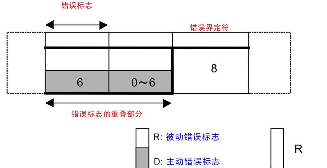
- Error Flag
- 6 consecutive dominant bits (logic 0) or recessive bits (logic 1), divided into active error flag and passive error flag.
- Active Error FlagSent by the node that detected the error, forcibly interrupting the transmission of the current frame and notifying all nodes in the network of the error occurrence.
- Passive Error FlagIt is sent by a node in the passive error state to avoid interfering with the normal communication of other nodes.
- Error Delimiter
- Composed of 8 consecutive recessive bits (logic 1), used to mark the end of the error frame. It ensures that all nodes can clearly identify the boundary of the error frame and resume normal communication flow after error handling is completed.
| Field Name | Composition | Function |
|---|---|---|
| Error Flag | Active error flag: 6 dominant bits; Passive error flag: 6 recessive bits | The active error flag forcibly interrupts the current frame transmission to notify network nodes of an error; the passive error flag avoids interfering with communication of other nodes. |
| Error Delimiter | 8 recessive bits | Marks the end of the error frame, helping all nodes identify the error frame boundary and resume normal communication. |
Overload Frame
An overload frame is a special frame in the CAN bus used to notify other nodes on the network that the receiving device needs more time to process data. It is usually sent when the receiving node cannot process the received data in time, to request the transmitting node to delay the transmission of the next frame. The composition of the overload frame is as follows:

- Overload Flag
- Composed of 6 consecutive dominant bits (logic 0), sent by the receiving node to notify other nodes on the network that the receiving device needs more time to process data, thereby requesting a delay in the transmission of the next frame.
- Multiple nodes can send overload flags simultaneously; these flags are superimposed to form a longer sequence of dominant bits.
- Overload Delimiter
- Composed of 8 consecutive recessive bits (logic 1), used to mark the end of the overload frame.
- It ensures that all nodes can clearly identify the boundary of the overload frame and resume normal communication after overload handling is completed.
| Field Name | Composition | Function |
|---|---|---|
| overload flag | 6 consecutive dominant bits | Sent by the receiving node to inform other nodes on the network that it needs more time to process data, requesting a delay in the next frame transmission. |
| overload delimiter | 8 consecutive recessive bits | Marks the end of an overload frame, helping all nodes identify its boundary and thereby resume normal communication flow. |
The overload frame usesoverload flagandoverload delimiterThe two fields serve to identify and handle the insufficient processing capability of the receiving node.
When the receiving node cannot process data in time, it sends an overload flag (6 dominant bits) to notify other nodes on the network to delay the transmission of the next frame; then, through the overload delimiter (8 recessive bits), it clearly marks the end of the overload frame.
The design of the overload frame ensures that nodes in the network can coordinate communication under high load, avoiding data loss or errors.
Bit stuffing
Bit stuffing is an important mechanism in the CAN protocol for ensuring signal synchronization during data transmission.
Bit stuffing inserts a stuffing bit of opposite polarity after five consecutive bits of the same polarity, ensuring that there is always a level change on the bus, thereby maintaining synchronization between the transmitter and receiver.
Stuffing is performed only from the start of frame to the CRC field, avoiding interference with other parts. After detecting the stuffing bit, the receiver automatically removes it to restore the original data. This mechanism is crucial for preventing signal synchronization problems and improving the reliability of CAN bus communication.
Core purpose
By inserting a stuffing bit of opposite polarity after five consecutive bits of the same polarity, it avoids long runs of ‘0’ or ‘1’ levels that could cause bus synchronization problems, thereby improving communication reliability.
Bit stuffing rules
When five consecutive bits of the same polarity appear in the data, a stuffing bit with the opposite polarity is inserted at the sixth bit.
This mechanism breaks up potentially long runs of the same level, ensuring that there is always a level change on the bus, thereby maintaining synchronization between the transmitter and receiver.
Stuffing range
From the start of frame to the CRC field,
- Example 1:
- Original data: 110000011
- Analysis: No five consecutive bits of the same polarity appear, so no stuffing is required.
- Actual transmitted data: 110000011
- Receiver directly recovers original data: 110000011
- Example 2:
- Original data: 0111111
- Analysis: There are 5 consecutive '1’s, insert a ‘0’ at the 6th bit.
- Actual transmitted data: 01111101
- Receiver detects and removes the stuffed bit, recovering the original data: 0111111
- Example 3:
- Original data: 1000001111
- Analysis: There are 5 consecutive '0’s, insert a ‘1’ at the 6th bit. After inserting the ‘1’, there are five consecutive '1’s, so a ‘0’ needs to be added at the last bit.
- Actual transmitted data: 100000111110
- Receiver detects and removes the stuffed bits, recovering the original data: 1000001111
CAN Waveform Example Analysis
Standard Data Frame

CAN communication is determined by a pair of differential signal lines, but there is only one CAN waveform above. This is because the waveform was acquired by a logic analyzer, which automatically converts the differential signal into a logic signal. Then we analyze the waveform.
Start of frame
First is the start of frame. The start of frame consists of a fixed dominant bit (logic 0) and is used to mark the beginning of the data frame.

Arbitration Field
Next is the 12-bit arbitration field. The first 11 bits are the identifier (ID), and the last bit is the Remote Transmission Request (RTR) bit. The identification diagram is shown below. The bits marked with a red × represent stuffed bits, so the corresponding bits need to be ignored during actual analysis. The RTR bit in the last position is a dominant bit (logic 0), so the currently transmitted frame is a data frame.

Control field
After the arbitration field is the 6-bit control field, including 1 IDE bit, 1 reserved bit (R0), and 4 data length code (DLC) bits. The identification diagram is shown below. The IDE bit is a dominant bit (logic 0), so the current frame is a standard frame. The reserved bit R0 defaults to a dominant bit (logic 0). The DLC bits in the last four positions are 0001, indicating that 8 bits of data will be sent later.

Data field
Next is the 8-bit data field, which is used to carry the actual communication data content. The identification diagram is shown below. The data to be sent is 00000001, and then continue analyzing downward.

CRC check field

ACK field
The next two bits are the ACK field (Acknowledgment Field). The ACK field consists of 2 bits, including 1 ACK slot and 1 ACK delimiter. When the receiving device successfully receives the data frame, it returns a dominant bit in the ACK slot as an acknowledgment signal, indicating that the data frame has been correctly received. The ACK delimiter is fixed to recessive 1, used to mark the end of the ACK field. The identification diagram is shown below:

Finally, the end of frame consists of 7 consecutive recessive bits (logic 1), which clearly marks the end of the data frame.
Standard Remote Frame

Start of frame
First is the start of frame, which consists of a fixed dominant bit (logic 0) and is used to mark the beginning of the data frame, as indicated in the figure below.

Arbitration Field
Next is the 12-bit arbitration field, in which the first 11 bits are the identifier (ID) and the last bit is the remote transmission request (RTR) bit. The identification diagram is shown below. The bits marked with red × indicate stuff bits, so the corresponding bits need to be ignored during actual analysis. The last RTR bit is a recessive bit (logic 1), and by observation it can be seen that there are no data bits to be transmitted afterward, so the currently transmitted frame is a remote frame.

Control field
After the arbitration field is the 6-bit control field (Control Field), including 1 IDE bit, 1 reserved bit (R0), and 4 data length code (DLC) bits. The identification diagram is shown below. The IDE bit is a recessive bit (logic 1), so the current frame is an extended remote frame. The reserved bit R0 defaults to a dominant bit (logic 0). The DLC bits of the last four bits are 0001, but since the current frame is a remote frame, no data will be sent.

CRC check field
The CRC check field consists of a 15-bit CRC check code and a 1-bit CRC delimiter, used to detect whether errors occur during data transmission. The identification diagram is shown below. The last CRC delimiter is fixed to recessive 1, used to clearly indicate the end position of the CRC field.

ACK field
The next two bits are the ACK field (Acknowledgment Field). The ACK field consists of 2 bits, including 1 ACK slot and 1 ACK delimiter. When the receiving device successfully receives the data frame, it returns a dominant bit in the ACK slot as an acknowledgment signal, indicating that the data frame has been correctly received. The ACK delimiter is fixed to recessive 1, used to mark the end of the ACK field. The identification diagram is shown below:

Finally, the end of frame is composed of 7 consecutive recessive bits (logic 1).
Extended data frame

Start of frame
First is the start of frame, which consists of a fixed dominant bit (logic 0) and is used to mark the beginning of the data frame, as indicated in the figure below.

Extended frame
Based on the waveform length and the yellow marker above, it can be determined that this frame is an extended frame. Therefore, in the next 12 bits, the first 11 bits are the identifier (ID), and the last bit is the SRR bit. The identification diagram is shown below. The bits marked with a red × are stuff bits, so the corresponding bits need to be ignored during actual analysis. The SRR bit is a recessive bit (logic 1).

Next is the 1-bit IDE bit. The IDE bit is a recessive bit (logic 1), so the current frame is an extended frame. However, whether it is an extended remote frame or an extended data frame still requires further analysis.

In the next 19 bits, the first 18 bits are also ID bits, and the last bit is the RTR bit, as shown in the diagram below. The RTR bit in the last position is a dominant bit (logic 0), so the currently transmitted frame is an extended data frame. Continue the analysis.

Control field
The next six bits are the control field (Control Field), including 2 reserved bits (R1 and R0) and a 4-bit data length code (DLC), as shown in the diagram below. The DLC bits in the last four positions are 0001, indicating that 8 bits of data will be sent next.

Data field
Next is the 8-bit data field, which is used to carry the actual communication data content, as shown in the diagram below. The data to be sent is 00000001.

CRC check field
The CRC check field consists of a 15-bit CRC check code and a 1-bit CRC delimiter. It is used to detect whether errors occur during data transmission, as shown in the diagram below. The CRC delimiter in the last position is fixed to recessive 1, which is used to clearly mark the end of the CRC field.

ACK field
The next two bits are the ACK field (Acknowledgment Field). The ACK field consists of 2 bits, including 1 ACK slot and 1 ACK delimiter. When a receiving device successfully receives a data frame, it returns a dominant bit in the ACK slot as an acknowledgment signal, indicating that the data frame has been correctly received. The ACK delimiter is fixed to recessive 1, which is used to mark the end of the ACK field, as shown in the diagram below.

Finally, the end of frame consists of 7 consecutive recessive bits (logic 1), which clearly marks the end of the data frame.
Core mechanisms and communication principles of the CAN bus
Bit time
In CAN bus communication,**Bit time refers to the time required to transmit one logical bit,**It is one of the core concepts for achieving reliable data transmission in the CAN protocol, directly affecting the communication baud rate and signal synchronization accuracy. As the basis of asynchronous communication, all nodes maintain synchronization through an agreed bit time.
The CAN protocol divides bit time into multiple time segments, which together determine the signal sampling and synchronization mechanism. Specifically, it includes the following parts:

- Sync Segment
The sync segment is the first part of the bit time,fixed to 1 time quantum(TQ (time quantum) is the basic unit of bit time, and all time segments are divided based on the time quantum.), mainly used to detect signal edges and achieve hard synchronization.
During the start of frame (SOF) phase, the receiving node forcibly adjusts its own clock according to the falling edge of the bus signal to align with the bus signal, thereby ensuring that all nodes remain synchronized at the initial stage of communication.
- Propagation Segment
The propagation segment is used to compensate for the propagation delay of the signal on the bus and the response time of the input comparator. Its length is usually 1 to 8 time quanta (TQ), and the specific value is determined by configuration. This
time segment allows the signal to propagate on the physical medium and ensures that all nodes can receive a stable signal, thereby avoiding sampling errors caused by propagation delay.
- Phase Buffer Segment 1 (Phase Segment 1)
Phase Buffer Segment 1 is a configurable part of the bit time, usually 1 to 8 time quanta (TQ),mainly used to adjust the position of the sampling point to ensure that the sampling point is located in a stable signal region.。
If it is detected that the signal edge arrives early,,the phase buffer segment can be shortened 1 to achieve resynchronization,thereby dynamically compensating for the effects of clock deviation or signal jitter.。- Phase Segment 2
Phase Segment 2 is similar to Phase Segment 1, and is also a configurable part of the bit time, typically ranging from 1 to 8 time quanta (TQ).
It is mainly used to handle situations where signal edges arrive late.。If the signal edge is delayed,It can be handled by extending the phase buffer segment 2 to achieve resynchronization,thereby ensuring that the receiving node can sample the signal at the correct time.,improving the reliability of data transmission.。The role of bit time
- Ensure synchronization: By dividing the time segments, CAN nodes can dynamically adjust the sampling point when signal edges occur, compensating for clock deviations and signal delays, thereby achieving synchronization among multiple nodes.
- Improve anti-interference capability: Set the sampling point in a stable signal region (e.g., at 87.5% of the bit time) to avoid misjudgment caused by signal edge jitter or interference.
- Support flexible configuration: By adjusting the lengths of various time segments (such as the propagation segment, phase buffer segments, etc.), it can adapt to different baud rates and network environments.
Hard Synchronization and Resynchronization
In CAN communication, because asynchronous communication is used and there is no independent clock line, each node relies on its local crystal oscillator for data transmission. However, clock drift of the crystal oscillator causes the timing between nodes to gradually shift, eventually leading to sampling errors. To solve this problem, the CAN protocol implements dynamic timing adjustment through two mechanisms: hard synchronization and resynchronization:
- Hard synchronization forcibly aligns the clocks of all nodes at the start-of-frame stage, eliminating the initial phase deviation.;
- Resynchronization, on the other hand, dynamically adjusts the length of the phase buffer segments based on real-time detection of signal edges during data transmission to compensate for clock drift.。
These two mechanisms work together, combined with the bit time division (synchronization segment, propagation segment, phase segments I/II) and the quantitative management of time quanta (Tq), to ensure that all nodes accurately read the bus level at the sampling point, thereby achieving highly reliable data transmission in asynchronous communication without an independent clock line. In this subsection, hard synchronization and resynchronization will be explained in detail.
Hard synchronization
In CAN communication, hard synchronization is an important mechanism to ensure consistent initial timing among all nodes. Its core function isto forcibly align the timing of each node during the start-of-frame (SOF) stage, thereby eliminating the initial phase difference caused by local crystal oscillator variations.。
The trigger condition for hard synchronization isWhen the bus detects a falling edge of the dominant level (logic 0) from the idle state (i.e., the edge of the SOF bit), the node immediately adjusts its own timing to align the synchronization segment of the current bit to this edge.。
This process can be divided into the following steps:
- The nodecontinuously monitors level changes during the bus idle period.;
- whenWhen a falling edge of SOF is detected and the edge falls within the synchronization segment, hard synchronization is triggered.;
- The node forcibly adjusts its timing, aligning the start of the synchronization segment of the current bit to that edge, and restarts the counting of subsequent bit time.。

However,The scope of hard synchronization is limited; it only takes effect at the beginning of a message frame and can only solve the initial phase offset problem.。
Resynchronization
In CAN communication,Resynchronization is a key mechanism for solving dynamic phase errors caused by clock drift or signal interference during communication.。
Unlike hard synchronization, resynchronization is not limited to the frame start phase, butcontinues to function throughout the entire data transmission process.。Its core function is to dynamically adjust the position of the sampling point,,ensuring that the receiving node can read the bus level at the correct time,,thereby maintaining communication reliability.。
Specifically,The trigger condition for resynchronization is when a deviation is detected between a signal edge (such as a change from dominant to recessive level) and its expected position.。
- If the signal edge arrives early, it indicates that the transmitting node’s clock is faster than the receiving node’s; in this case, the receiving node advances the sampling point by shortening Phase Buffer Segment 1.
- Conversely, if the signal edge arrives late, it indicates that the transmitting node’s clock is slower than the receiving node’s; the receiving node delays the sampling point by extending Phase Buffer Segment 2.
This dynamic adjustment process depends onthe Synchronization Jump Width (SJW), which defines


The advantage of resynchronization lies in its flexibility and real-time capability, effectively coping with challenges caused by clock drift or signal propagation delay during communication.
However,The adjustment range of resynchronization is limited by SJW the configuration of,If the phase error exceeds SJW the limit,it may lead to sampling errors,thereby affecting the reliability of communication。
Therefore, resynchronization and hard synchronization work together to constitute the complete synchronization mechanism in the CAN protocol: hard synchronization provides initial alignment for communication, while resynchronization dynamically compensates for errors in subsequent transmissions, ensuring the accuracy and stability of data transmission.
Arbitration Rules
In CAN bus communication, because multiple nodes share the same bus, only one data frame can be transmitted at the same time, so an efficient arbitration mechanism is required to ensure orderly data transmission.
The CAN protocol, through the collaboration of carrier sensing, non-destructive arbitration, and readback mechanisms, achieves efficient and conflict-free communication among multiple nodes.
Carrier Sensing
BeforeBefore sending data, each node first listens to the bus stateOnly when the bus is in an idle state (i.e., no other node is sending data) is the node allowed to start sending data.
This mechanism is similar to ‘Carrier Sense Multiple Access (CSMA)’ in Ethernet, and can effectively avoid multiple nodes occupying the bus at the same time.
If two or more nodes detect the bus idle almost simultaneously and start sending data,then they enter the non-destructive arbitration phase。Non-destructive Arbitration
Non-destructive arbitration is the core of the CAN bus arbitration mechanism, and its core principle isbased on the wired-AND mechanism
- When all nodes send a recessive level (logic 1), the bus is recessive;
- As long as one node sends a dominant level (logic 0), the bus is dominant.
This mechanism ensures that even if multiple nodes transmit data simultaneously, the signals on the bus will not be corrupted; instead, the dominant level prevails. The arbitration process is as follows:
- The identifier (ID) field of each data frame is used for arbitration priority,The smaller the ID, the higher the priority.。
- When multiple nodes transmit data simultaneously, they compare, bit by bit, the ID they are sending with the actual level on the bus.
- If a node is sending a recessive level (1) but detects a dominant level (0) on the bus, it means a higher-priority node is transmitting data. The node immediately stops transmitting and enters listen mode, waiting for the next bus idle condition to retry transmission.
- If a node is sending a dominant level (0) and the bus also has a dominant level (0), the node continues transmitting, indicating that it currently has the highest priority.
Readback mechanism
To ensure the correctness of arbitration and the reliability of data transmission, CAN nodescontinuously read back the signals on the bus while transmitting data,and compare them with the data they are sending.
This mechanism ensures that lower-priority nodes can withdraw from transmission in time, avoiding interference with higher-priority nodes’ communication.
Error states
In the CAN protocol, a node’s error state is based on the values of the**Transmit Error Counter (TEC)andReceive Error Counter (REC)**dynamically adjusted based on the values of these counters.
Through three different error states—Error Active state, Error Passive state, and Bus-Off state,
the CAN protocol achieves effective management and isolation of faulty nodes, while ensuring the reliability and stability of communication.
Error Active state
When a node’s Transmit Error Counter (TEC) and Receive Error Counter (REC) are both less than or equal to 127, the node is in the Error Active state.
In this state, the node can participate normally in bus communication and actively sends an active error flag (dominant bit) when an error is detected. This dominant flag forcibly overrides the bus signal to notify other nodes that an error currently exists.
Because dominant bits have higher priority, this mechanism can quickly propagate error information, thereby ensuring errors are handled in a timely manner and maintaining the reliability of bus communication.
Error Passive State
If a node’s Transmit Error Counter (TEC) or Receive Error Counter (REC) exceeds 127 (usually triggered by TEC), the node enters the Error Passive state.
In this state, the node can still participate in communication, but its behavior is restricted: it cannot actively send dominant error flags; instead, it sends passive error flags (recessive bits) to avoid disturbing the bus. In addition, after each transmission, a delay of 8 recessive bits must be inserted before attempting to communicate again.
It is worth noting that if only a node in the Error Passive state detects an error while other active nodes do not, the bus is considered error-free and communication continues.
This design both limits the impact of low-reliability nodes on the bus and ensures the communication efficiency of high-reliability nodes.
Bus-Off State
When a node’s Transmit Error Counter (TEC) exceeds 255, the node enters the Bus-Off state.
In this state, the node is completely prohibited from communicating; it can neither send nor receive data, to prevent it from causing further interference to the bus.
To resume communication, the node needs to detect 128 consecutive occurrences of 11 recessive bits (i.e., the bus is idle for a sufficiently long time), then reset TEC and REC to 0, thereby returning to the Error Active state and rejoining bus communication.
This mechanism aims to isolate severely faulty nodes while providing them with an opportunity to rejoin the bus.
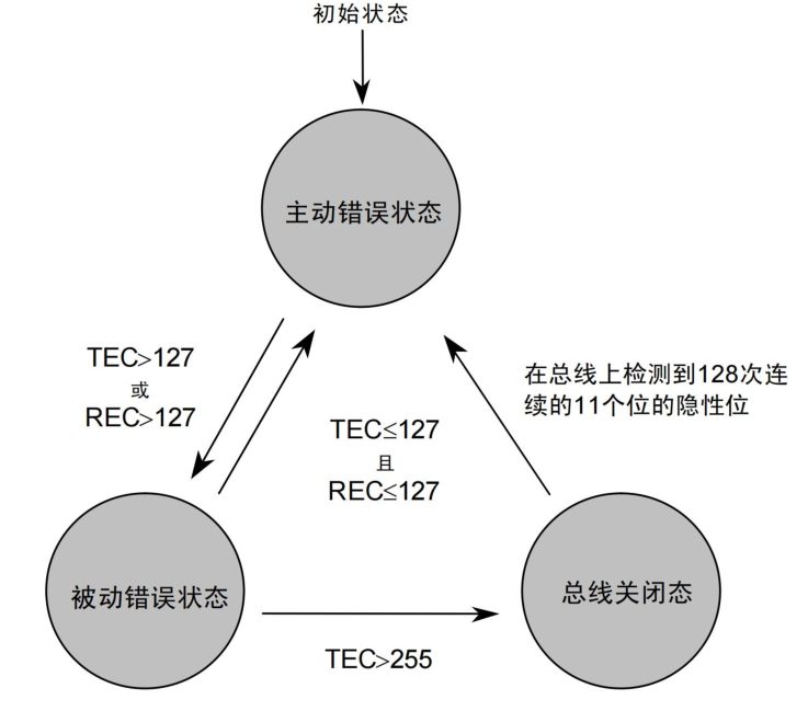
The more specific conditions for changing the Receive Error Counter (REC) and Transmit Error Counter (TEC) are shown in the following table:
| No. | Conditions for changing the receive and transmit error counter values | Transmit Error Counter (TEC) | Receive Error Counter (REC) |
|---|---|---|---|
| 1 | When the receiving unit detects an error. Exception: When the receiving unit detects a ‘bit error’ while sending an error flag or overload flag, the receive error counter is not incremented. | — | +1 |
| 2 | When the first bit detected by the receiving unit after sending an error flag is dominant. | — | +8 |
| 3 | When the transmitting unit outputs an error flag. | +8 | — |
| 4 | When the transmitting unit detects a bit error while sending an active error flag or overload flag. | +8 | — |
| 5 | When the receiving unit detects a bit error while sending an active error flag or overload flag. | — | +8 |
| 6 | When each unit detects 14 consecutive dominant bits from the very beginning of an active error flag or overload flag. Thereafter, each time it detects 8 consecutive dominant bits. | When transmitting: +8 | When receiving: +8 |
| 7 | When 8 consecutive dominant bits are detected appended after a passive error flag. | When transmitting: +8 | When receiving: +8 |
| 8 | When the transmitting unit finishes sending data normally (when ACK is returned and no error is detected up to the end of frame). | When TEC=0: ±0; otherwise -1 | — |
| 9 | When the receiving unit finishes receiving data normally (when no error is detected up to CRC and ACK is returned normally). | — | When 1≤REC≤127: -1; when REC=0: ±0; when REC>127: set REC=127 |
| 10 | When a unit in the bus-off state detects 128 occurrences of 11 consecutive recessive bits. | TEC=0 | REC=0 |
Error Detection Mechanism
The CAN (Controller Area Network) protocol effectively improves communication reliability through multiple error detection methods.
The error detection mechanism can be divided into the following five types: bit error, stuff error, CRC error, form error, and ACK error.
Bit Error
A bit error refers toan error detected when the transmitting unit, during communication, compares its own output level with the bus level (excluding stuff bits) and finds a mismatch.。
This type of error usually indicates a conflict or interference between the transmitting node and the signal on the bus.
Bit errors can occur in data frames、remote frames、and in any segment of error frames and overload frames.(From SOF to EOF)。Since a bit error is detected by the transmitting unit itself, its detecting unit is the transmitting unit.
Stuff Error
A stuff error refers toan error triggered when the receiving unit continuously detects 6 bits of the same level in a segment that requires bit stuffing.。
The CAN protocol specifies that in a bit stuffing segment, after every 5 consecutive bits of the same level, a stuff bit of the opposite level must be inserted to ensure DC balance of the signal.
If the receiving unit detects 6 consecutive bits of the same level, it considers a stuff error to have occurred.
Stuff errors mainly occur in any segment of data frames and remote frames.(From SOF to EOF),Its detection unit is the receiving unit.。CRC error
A CRC error refers to**The CRC check value calculated by the receiving unit based on the received data is inconsistent with the CRC sequence actually received in the frame.**is the error detected when.
CRC check is a key mechanism in the CAN protocol for verifying data integrity. If the check fails, it indicates that the data may have been corrupted or lost during transmission.
CRC The error usually occurs in the CRC segment.,Its detection unit is the receiving unit.。Format error
A format error refers to**an error triggered when the receiving unit detects a format opposite to the fixed-format bit field while parsing the frame.**For example, illegal values of the CRC delimiter, ACK delimiter, or EOF may all cause a format error.
This type of error usually indicates that the frame structure does not conform to the CAN protocol specification.
Format errors can occur in the CRC delimiter、ACK delimiter、EOF field,as well as in the error delimiter and overload delimiter.,Its detection unit is the receiving unit.。ACK error
An ACK error refers toan error triggered when the transmitting unit detects a recessive level in the ACK slot.。
In the CAN protocol,When the transmitting unit completes the transmission of a data frame or remote frame, it waits in the ACK slot for an acknowledgment signal (dominant level) from other nodes.。
If the transmitting unit does not detect a dominant level, it considers that no acknowledgment signal was received, thereby triggering an ACK error.
ACK Errors mainly occur in the data frame and remote frame's ACK slot segment,Its detection unit is the transmitting unit.。CAN bus protocol and standard specifications
In modern communication systems, the ISO seven-layer network model is a classic framework for describing and standardizing network communication processes. It divides network communication into seven layers, from the bottom physical signal transmission to the top application services, and each layer has specific functions and roles.
Although the design of the CAN protocol does not fully follow the ISO seven-layer network model, its functions can be mapped to some layers of the model.
The CAN protocol mainly focuses onPhysical Layer、Data Link LayerandTransport Layersome of the functions.
ISO seven-layer network model
Physical Layer
The physical layer is responsible for physical signal transmission between devices, defining the electrical signals, hardware specifications, and communication media required for communication. It covers communication modes (such as simplex, half-duplex, full-duplex), signal levels (such as high and low levels representing logic 0 and 1), hardware specifications (such as cables, connectors, transceivers), and bit timing conditions (such as bit synchronization, sampling points), thereby ensuring reliable data transmission over the physical medium.Data Link Layer
The data link layer organizes the bit sequence received from the physical layer into meaningful data frames and provides error detection and control functions. Its specific items include the format of data frames (such as frame start, identifier, data field, CRC check), access control methods (such as CSMA/CD, CSMA/CA), and error detection and correction mechanisms (such as CRC check, ACK response), to ensure the accuracy and integrity of data transmission on the link.Network Layer
The network layer is responsible for routing and relaying data packets, ensuring that data can be efficiently transmitted from the source device to the destination device. Through functions such as routing (such as static routing, dynamic routing), address management (such as IP address allocation), and packet fragmentation and reassembly, it enables data transmission across networks and provides support for communication in complex network environments.Transport Layer
The transport layer ensures the reliability of data transmission, controlling data order, error recovery, and flow control. Through mechanisms such as data transmission order control (such as sequence numbers, acknowledgment mechanisms), error recovery (such as retransmission mechanisms), and flow control (such as sliding window protocols), it guarantees the consistency, integrity, and efficiency of data during end-to-end transmission.Session Layer
The session layer manages the establishment, maintenance, and termination of communication sessions, ensuring that data can be correctly transmitted during the session. Through functions such as session establishment and termination (such as handshake protocols), session synchronization (such as checkpoint mechanisms), and session recovery (such as resumable transfer), it coordinates interactions between applications and improves the stability and efficiency of communication.Presentation Layer
The presentation layer is responsible for converting the representation form of data, ensuring data compatibility between different systems. Through functions such as data format conversion (such as text encoding, image formats), data encryption and decryption, and data compression and decompression, it enables data to be seamlessly exchanged and processed between different platforms and applications.Application Layer
The application layer provides network service interfaces for applications and implements specific application functions. It directly serves end users through application protocols (such as HTTP, FTP, SMTP), user interfaces (such as browsers, email clients), and data services (such as file transfer, email), meeting diverse network application needs.
CAN protocol physical layer and data link layer
The CAN protocol mainly focuses on the physical layer and the data link layer
- Physical layer in the CAN protocol
The physical layer is responsible for defining the actual signal transmission method, using NRZ (Non-Return-to-Zero) encoding, and inserting stuffing bits after every 6 bits.
It also specifies bit timing and sample count, which users can choose according to their needs.
Synchronization is achieved through the synchronization segment (SS) and has resynchronization capability. However, specific details such as signal levels, communication speed, sampling points, electrical characteristics of drivers and buses, and connector shapes are not defined in the protocol and need to be determined by the user based on system requirements.
- Data link layer in the CAN protocol
- **MAC sublayer (Media Access Control sublayer)**It is responsible for organizing data into frames, including data frames, remote frames, error frames, and overload frames. It also handles arbitration during data conflicts, deciding which message continues to be sent based on priority, and responds via ACK (acknowledgment) and NACK (negative acknowledgment). In addition, the MAC sublayer detects and reports CRC errors, stuffing bit errors, bit errors, ACK errors, and format errors, and has fault confinement capability that can automatically distinguish temporary errors from persistent errors and isolate faulty nodes.
- **LLC sublayer (Logical Link Control sublayer)**It is responsible for the selection of received messages, supporting point-to-point connections, broadcast, and multicast; it also provides error recovery functions, performing retransmission control when errors are detected to ensure reliable data transmission.

After ISO standardization, the CAN protocol is divided into two standards: ISO11898 and ISO11519-2.
The definitions of these two standards are the same at the data link layer, but they differ at the physical layer:
- ISO11898 is a CAN high-speed communication standard with a communication speed of 125kbps-1Mbps
- ISO11519-2 is a CAN low-speed communication standard with a communication speed below 125kbps.


Enable CAN
Device Tree
1234567891011121314151617181920212223242526272829303132333435363738 | can0: can@fe570000 { compatible = "rockchip,rk3568-can-2.0"; // Specify the device compatibility string for matching the driver reg = <0x0 0xfe570000 0x0 0x1000>; // Define the register address range: base address is 0xfe570000, length is 0x1000 bytes interrupts = <GIC_SPI 1 IRQ_TYPE_LEVEL_HIGH>; // Define interrupt information: use GIC SPI interrupt, interrupt number 1, trigger type is high-level clocks = <&cru CLK_CAN0>, <&cru PCLK_CAN0>; // Define the clock source: reference CLK in the CRU node_CAN0 (baud rate clock) and PCLK_CAN0 (APB bus clock) clock-names = "baudclk", "apb_pclk"; // Name the clock signals: baud rate clock and APB bus clock, respectively. resets = <&cru SRST_CAN0>, <&cru SRST_P_CAN0>;// Define the reset signal: reference SRST in the CRU node._CAN0 (main reset) and SRST_P_CAN0 (APB reset) reset-names = "can", "can-apb"; // Name the reset signals: CAN main reset and APB reset, respectively. tx-fifo-depth = <1>; // Define the transmit FIFO depth: depth is 1, meaning only one message to be sent can be stored at a time. rx-fifo-depth = <6>; // Define the receive FIFO depth: depth is 6, meaning up to 6 received messages can be stored simultaneously. status = "disabled"; // Define the initial device state: disabled by default, the device will not be enabled at startup.};can1: can@fe580000 { compatible = "rockchip,rk3568-can-2.0"; reg = <0x0 0xfe580000 0x0 0x1000>; interrupts = <GIC_SPI 2 IRQ_TYPE_LEVEL_HIGH>; clocks = <&cru CLK_CAN1>, <&cru PCLK_CAN1>; clock-names = "baudclk", "apb_pclk"; resets = <&cru SRST_CAN1>, <&cru SRST_P_CAN1>; reset-names = "can", "can-apb"; tx-fifo-depth = <1>; rx-fifo-depth = <6>; status = "disabled";};can2: can@fe590000 { compatible = "rockchip,rk3568-can-2.0"; reg = <0x0 0xfe590000 0x0 0x1000>; interrupts = <GIC_SPI 3 IRQ_TYPE_LEVEL_HIGH>; clocks = <&cru CLK_CAN2>, <&cru PCLK_CAN2>; clock-names = "baudclk", "apb_pclk"; resets = <&cru SRST_CAN2>, <&cru SRST_P_CAN2>; reset-names = "can", "can-apb"; tx-fifo-depth = <1>; rx-fifo-depth = <6>; status = "disabled";}; |
Although there are 3 CAN device nodes here, on the Xunwei baseboard there is only one CAN interface due to pin muxing issues. The corresponding schematic section is shown below:

It can be seen that CAN1 is used on the development board, and inrk3568.dtsiIn the device tree, the status of the can1 node is set to disabled, meaning it is not enabled, so there must be an addition to this node in another device tree.
123456789 | //CAN interface&can1 { status = "okay";// Specify the device compatibility string. compatible = "rockchip,rk3568-can-2.0";// Set the device status to "okay", indicating the device is enabled. assigned-clocks = <&cru CLK_CAN1>;// Allocate the clock source: reference CLK_CAN1 in the CRU (Clock and Reset Unit) node. assigned-clock-rates = <150000000>; //If can bitrate lower than 3M, the clock-rates should set 100M, else set 200M. // Set the allocated clock frequency to 150MHz. If the CAN baud rate is lower than 3Mbps, it is recommended to set the clock frequency to 100MHz; otherwise, set it to 200MHz. pinctrl-names = "default";// Define the name of the pin control state; the default state is "default". pinctrl-0 = <&can1m1_pins>;// Reference the pin configuration node &can1m1_pins to define the pin muxing and electrical properties of CAN1.}; |
In addition to enabling the device tree, the corresponding driver must also be enabled in the kernel configuration file. The specific path is as follows:
1234 | > Networking support > CAN bus subsystem support > CAN Device Drivers <*> Platform CAN drivers with Netlink support |
Porting and usage of CAN tools
iproute2andcan-utilsThey are two essential tools. They provide basic management and advanced operation functions for the CAN interface respectively, helping us easily configure, test, and debug the CAN bus.
Porting the iproute2 tool
iproute2 is a toolset for network management, including commands such as ip, ss, and tc. The corresponding source code archive can be downloaded from the official website.

Compile:
123456 | ./configure# Modify the Makefile generated by configure, change the following to 'lib ip' to compile and use the ip tool.SUBDIRS=lib ipmake CC=/path/to/linux_sdk/prebuilts/gcc/linux-x86/aarch64/gcc-linaro-6.3.1-2017.05-x86_64_aarch64-linux-gnu/bin/aarch64-linux-gnu-gcc |
After compilation, the corresponding executable file will be generated in the ip directory. Copy this file to the development board.
Porting canutils tools
canutils is a commonly used CAN communication test toolkit, containing 5 independent programs: canconfig, candump, canecho, cansend, and cansequence. The introduction of each tool is as follows:
| Tool Name | Function description | Main configuration items / Additional features / Purpose |
|---|---|---|
| canconfig | Used to configure parameters of the CAN bus interface. | Bitrate Working mode (Mode), such as loopback mode (Loopback) or normal mode (Normal). |
| candump | Receives data from the CAN bus interface and prints it to standard output in hexadecimal format. | Can save the received data to a specified file. |
| canecho | Resends all data received from the CAN bus interface back to the CAN bus interface. | Used to test the loopback function of the CAN bus. |
| cansend | Sends specified data to the specified CAN bus interface. | Data is sent in CAN frame format, including frame ID and frame data. |
| cansequence | Automatically sends an incrementing numeric sequence to the specified CAN bus interface; supports receive mode to verify whether the received incrementing numbers are correct. | Used to test the data transmission integrity and stability of the CAN bus. |
Since canutils depends on the libsocketcan library, you need to compile libsocketcan first, and then compile canutils. The corresponding source code link for libsocketcan is:
Compile:
123456789101112 | $ export ARCH=arm64$ export CROSS_COMPILE=/path/to/linux_sdk/prebuilts/gcc/linux-x86/aarch64/gcc-linaro-6.3.1-2017.05-x86_64_aarch64-linux-gnu/bin/aarch64-linux-gnu-$ export PATH=$PATH:/path/to/linux_sdk/prebuilts/gcc/linux-x86/aarch64/gcc-linaro-6.3.1-2017.05-x86_64_aarch64-linux-gnu/bin/$ ./configure --host=aarch64-linux-gnu --prefix=/home/topeet/can/libsocketcan-0.0.12/out$ make && make install# After compilation, the corresponding files will be generated in the out directory of the current directory.$ ls outinclude lib share |
The canutils source code download address is
After decompressing, enter the corresponding directory, andconfig/autoconf/config.subModify the file, add the following contents respectively to add support for aarch64. The modifications are as follows:
12 | | aarch64 | aarch64_be \| aarch64-* | aarch64_be-* \ |
Then modify the configure configuration file, change the compiler on line 2604 to aarch64-linux-gnu-gcc. The modifications are as follows:
1 | at_ct_CC=aarch64-linux-gnu-gcc |
Compile:
123456789101112131415 | $ export ARCH=arm64$ export CROSS_COMPILE=/path/to/linux_sdk/prebuilts/gcc/linux-x86/aarch64/gcc-linaro-6.3.1-2017.05-x86_64_aarch64-linux-gnu/bin/aarch64-linux-gnu-$ export PATH=$PATH:/home/topeet/work/linux_sdk/prebuilts/gcc/linux-x86/aarch64/gcc-linaro-6.3.1-2017.05-x86_64_aarch64-linux-gnu/bin/$ ./configure \ --host=aarch64-linux-gnu \ --prefix=/path/to/canutils-4.0.6/out \ libsocketcan_LIBS="-L/path/to/libsocketcan-0.0.12/out/lib -lsocketcan" \ libsocketcan_LDFLAGS="-L/path/to/libsocketcan-0.0.12/out/lib" \ libsocketcan_CFLAGS="-I/path/to/libsocketcan-0.0.12/out/include" \ CFLAGS="-I/path/to/libsocketcan-0.0.12/out/include $ make && make install$ ls out/bin/candump canecho cansend cansequence |
Using CAN tools
Set the baud rate of the CAN interface.
The baud rate of the CAN interface can be set using the ip command. For example, the following command sets the baud rate of the CAN0 interface to 250 kbps:
1 | ip link set can0 type can bitrate 250000 |
Starting and stopping the CAN interface
After configuring the CAN interface baud rate, you need to start the CAN interface before it can be used.
- Method 1: Using the ifconfig command
ifconfig is a traditional network interface configuration tool. You can start the CAN interface with the following command:
1 | ifconfig can0 up |
Stopping the CAN interface:
1 | ifconfig can0 down |
- Method 2: Using the ip command
Starting the CAN interface
1 | ip link set can0 up |
Stopping the CAN interface
1 | ip link set can0 down |
Checking the CAN interface status
After starting the CAN interface, you can check its status using the ifconfig command and the ip command.
- Checking with ifconfig
1 | ifconfig can0 |
- Checking with the ip command
1 | ip -details link show can0 |
Testing communication with CAN tools
Receiving data with candump
candump is used to receive data from a CAN bus interface and print it to standard output in hexadecimal format.
Command format:candump <interface> [options]
1 | candump can0 -L & |
Set filter rules
There are two basic filter formulas:
<can id>:<can mask>Match a specific CAN frame- Indicates that when the received CAN ID meets the condition
<received can id> & mask == can id & maskit matches. - The mask determines which bits need to participate in the match; only the bits corresponding to 1 are checked.
- The can id is the target ID expected to match. This rule is usually used to filter frames that match a specific ID and format, for example, to receive only a certain standard frame or extended frame.
- Indicates that when the received CAN ID meets the condition
<can id>~<can mask>Excluding specific CAN frames is<can id>:<can mask>exactly the opposite, i.e., ignore frames that satisfy
the condition, and receive all other frames.- Indicates that when the received CAN ID meets the condition
<received can id> & mask != can id & maskit matches.
- Indicates that when the received CAN ID meets the condition
The CAN ID of a standard frame is 11 bits long, ranging from 0x000 to 0x7FF. In the filter rule, the upper 18 bits of the mask are usually set to 0, indicating that the
extended frame part is not considered;The CAN ID of an extended frame is 29 bits long, ranging from 0x00000000 to 0x1FFFFFFF. In its filter rule, the lower 11 bits of the mask can be flexibly set to 0 or 1 to decide whether to also match standard frames.
example
Matching a specific extended frame
1 | candump can0,12345678:1FFFFFFF |
- Meaning: Only receive extended frames, and the CAN ID exactly matches 0x12345678.
- Analysis:
- can id = 0x12345678。
- mask = 0x1FFFFFFF (matches all 29 bits, and requires an extended frame)
Matching a specific standard frame
1 | candump can0,123:C00007FF |
- Meaning: Only receive standard frames, and the CAN ID exactly matches 0x123.
- Analysis:
- can id = 0x123。
- mask = 0xC00007FF: the upper 18 bits are 0xC0000 (ignoring the extended frame part), and the lower 11 bits are 0x7FF (exactly matching the standard frame ID).
Matching standard frames and remote frames
1 | candump can0,123:800007FF |
- Meaning: Only receive standard frames or remote frames, and the CAN ID exactly matches 0x123.
- Analysis:
- can id = 0x123
- mask = 0x800007FF: the upper 18 bits are 0x80000 (allowing remote frames), and the lower 11 bits are 0x7FF (exactly matching the standard frame ID).
Excluding a specific extended frame
1 | candump can0,12345678~1FFFFFFF |
- Meaning: Exclude extended frames, and the CAN ID exactly matches 0x12345678.
- Analysis:
- can id = 0x12345678。
- mask = 0x1FFFFFFF (matches all 29 bits, and requires an extended frame). Use ~ to indicate exclusion of the match
Multiple matching rules
If you want to apply multiple matching rules, simply append them with commas. For example, only receive standard frames with CAN IDs exactly matching 0x123 and 0x456.
1 | candump can0,123:C00007FF,456:C00007FF |
Sending data using cansend
cansend is used to send different frames to a CAN bus interface. Examples of sending different frames are as follows:
- Sending a standard data frame
- Command format:
cansend <interface> <frame ID>#<data><interface>: CAN interface name (e.g., can0).
<frame ID>: The ID of the CAN frame (11 bits, hexadecimal).<data>: The data of the CAN frame (hexadecimal).
- Example: Send a standard data frame on can0 with ID 0x123 and data DE AD BE EF.
1 | cansend can0 123#DEADBEE |
- Send remote frame
- Command format:
cansend <interface> <frame ID>#R R: Indicates a remote frame.- Example: Send a standard remote frame to can0 with ID 0x123.
- Command format:
1 | cansend can0 123#R |
- Sending an extended data frame
- Command format:
cansend <interface> <frame ID>#<data> <frame ID>: The ID of the CAN frame (29 bits, hexadecimal).- Example: Send an extended data frame to can0 with ID 0x00000123 and data 12 34 56 78.
- Command format:
1 | cansend can0 00000123#12345678 |
- Sending an extended remote frame
- Command format:
cansend <interface> <frame ID>#R - R: Indicates a remote frame.
- Example: Send an extended remote frame to can0 with ID 0x00000123
- Command format:
1 | cansend can0 00000123#R |
CAN Application Programming
Creating a socket
The socket function is one of the most basic functions in network programming, used to create a socket.
A socket is the basic unit of network communication, providing a mechanism for inter-process communication.. Through the socket, applications can send and receive data packets, thereby achieving network communication.
socket()Used to create a socket, it is thefirst step. After successful creation, the returned socket descriptor is used for subsequentbind、listen、connect、send、recvoperations, etc.
Header file
12 |
Function prototype
1 | int socket(int domain, int type, int protocol); |
Return value
- Success: Returns a non-negative integer, representing the socket descriptor (socket fd)
- Failure: returns
-1, and setserrno
Parameter description
domainProtocol family (address family)
Specifies the protocol family used for communication, determiningaddress format and communication range. Common values:
| Protocol family | Description |
|---|---|
| AF_UNIX | Used for local communication (inter-process communication on the same machine), also known as AF_LOCAL. |
| AF_INET | IPv4 Internet protocol family, used for IPv4-based network communication. |
| AF_INET6 | IPv6 Internet protocol family, used for IPv6-based network communication. |
| AF_IPX | Novell’s IPX/SPX protocol family, used for Novell networks. |
| AF_NETLINK | Communication between the kernel and user space, used to receive kernel event notifications. |
| AF_X25 | ITU-T X.25/ISO-8208 protocol family, used for packet-switched networks. |
| AF_AX25 | Amateur radio AX.25 protocol family, used for amateur radio communication. |
| AF_ATMPVC | Used to access raw ATM PVCs (Permanent Virtual Circuits); ATM is a high-speed network communication technology. |
| AF_APPLETALK | AppleTalk protocol family, used to connect Mac computers and other devices. |
| AF_PACKET | Low-level packet interface, allowing applications to directly access network devices and send/receive raw packets. |
| AF_ALG | Interface to the kernel cryptographic API, allowing applications to use encryption services provided by the kernel. |
| PF_CAN | Protocol family for CAN (Controller Area Network) communication. |
typeSocket type
Specifies the data transmission method. Common values:
| Type | Description |
|---|---|
| SOCK_STREAM | Stream socket, providing connection-oriented, reliable, bidirectional byte-stream communication (e.g., TCP). |
| SOCK_DGRAM | Datagram socket, providing connectionless, unreliable, fixed-length datagram communication (e.g., UDP). |
| SOCK_RAW | Raw socket, allowing direct access to underlying protocols (e.g., IP, ICMP). |
| SOCK_SEQPACKET | Provides connection-oriented, reliable, fixed-length datagram communication. |
protocolProtocol type
Specifies the specific protocol to use, usually set to 0, determined by the system based ondomainandtypeAutomatic selection. Common values:
| Protocol | Description | Corresponding domain and type |
|---|---|---|
| IPPROTO_TCP | TCP protocol, used for SOCK_STREAM type | AF_INET or AF_INET6, SOCK_STREAM |
| IPPROTO_UDP | UDP protocol, used for SOCK_DGRAM type | AF_INET or AF_INET6, SOCK_DGRAM |
| IPPROTO_RAW | Raw protocol, used for SOCK_RAW type | AF_INET or AF_INET6, SOCK_RAW |
| CAN_RAW | Raw CAN protocol, used for CAN bus communication | PF_CAN, SOCK_RAW |
| CAN_BCM | Broadcast management protocol, used for more complex CAN communication | PF_CAN, SOCK_DGRAM |
Common combination examples
1234567891011121314151617181920 | // TCP IPv4 socketint fd = socket(AF_INET, SOCK_STREAM, 0);// UDP IPv4 socketint fd = socket(AF_INET, SOCK_DGRAM, 0);// Local process communicationint fd = socket(AF_UNIX, SOCK_STREAM, 0);// Raw CAN socket (most commonly used)int fd = socket(PF_CAN, SOCK_RAW, CAN_RAW);// Broadcast Manager (BCM) CAN socketint fd = socket(PF_CAN, SOCK_DGRAM, CAN_BCM);// ISO-TP (Transport layer over CAN)int fd = socket(PF_CAN, SOCK_DGRAM, CAN_ISOTP);// J1939 (commercial vehicle protocol)int fd = socket(PF_CAN, SOCK_DGRAM, CAN_J1939); |
example
123456789101112131415161718192021 | int main() { int sockfd; // Create CAN socket sockfd = socket(PF_CAN, SOCK_RAW, CAN_RAW); if (sockfd == -1) { perror("Socket creation failed"); return EXIT_FAILURE; } printf("CAN socket created successfully\n"); // Close socket (optional) close(sockfd); return 0;} |
Bind the socket
Function introduction
bind()Used to bind a socket tospecified local address。
In network programming, it is usually used to bind IP address and port number; in CAN communication in,bind()the main function is to bind the socket tothe specified CAN interface(such ascan0), thereby determining which CAN controller is used for data transmission and reception.
bind()is a CAN socket communicationone of the basic configuration steps, and must be called before data transmission and reception.
Header file
12 |
Function prototype
1 | int bind(int sockfd, const struct sockaddr *addr, socklen_t addrlen); |
Return value
- Success: returns
0 - Failure: returns
-1, and setserrno
Parameter description
sockfdSocket descriptor
bysocket()The socket file descriptor created by the function, indicating the socket to be bound.
addrAddress structure pointer: a structure pointer pointing to the address information to be bound. In different communication scenarios, the actual structure used differs:IPv4:
struct sockaddr_inIPv6:
struct sockaddr_in6CAN:
struct sockaddr_can
When callingbind()when it needs to be cast tostruct sockaddr *type.
addrlenAddress structure length: indicatesaddrthe size of the pointed-to address structure, usually usingsizeof()calculate:IPv4:
sizeof(struct sockaddr_in)IPv6:
sizeof(struct sockaddr_in6)CAN:
sizeof(struct sockaddr_can)
bind example in CAN communication
123456 | struct sockaddr_can addr;addr.can_family = AF_CAN;addr.can_ifindex = if_nametoindex("can0");bind(fd, (struct sockaddr *)&addr, sizeof(addr)); |
Description:
can_family: must be set toAF_CANcan_ifindex: specify the CAN interface index (e.g.can0)- After binding, the socket will only communicate on the specified CAN interface.
example
123456789101112131415161718192021222324252627282930313233343536373839 | int main(int argc, char *argv[]) { int sockfd; // Socket descriptor struct sockaddr_can addr; // CAN address structure struct ifreq ifr; // Used to obtain network interface information // Create CAN socket sockfd = socket(PF_CAN, SOCK_RAW, CAN_RAW); if (sockfd < 0) { printf("Socket creation failed"); return -1; } // Specify the CAN interface name to bind strncpy(ifr.ifr_name, "can0", IFNAMSIZ - 1); // Use ioctl to get the index number of the CAN interface ioctl(sockfd, SIOCGIFINDEX, &ifr) // Set CAN address structure addr.can_family = AF_CAN; // CAN address family addr.can_ifindex = ifr.ifr_ifindex; // CAN interface index number // Bind the socket to the specified CAN interface bind(sockfd, (struct sockaddr *)&addr, sizeof(addr)) // close the socket (in actual applications, you can continue sending/receiving data) close(sockfd); return 0;} |
The above code uses the ioctl system call viaSIOCGIFINDEXmacro to obtain the CAN interface index number, exceptSIOCGIFINDEXBesides the macro, there are macros with other functions in network devices, as shown in the following table:
| command | Function description |
|---|---|
| SIOCGIFADDR | Get the IP address of the network interface |
| SIOCSIFADDR | Set the IP address of the network interface |
| SIOCGIFNETMASK | Get the subnet mask of the network interface |
| SIOCSIFNETMASK | Set the subnet mask of the network interface |
| SIOCGIFBRDADDR | Get the broadcast address of the network interface |
| SIOCSIFBRDADDR | Set the broadcast address of the network interface |
| SIOCGIFDSTADDR | Get the destination address of the network interface (the peer address of a point-to-point interface) |
| SIOCSIFDSTADDR | Set the destination address of the network interface |
| SIOCGIFHWADDR | Get the hardware address of the network interface (e.g., MAC address) |
| SIOCSIFHWADDR | Set the hardware address of the network interface (usually not commonly used, as hardware addresses are mostly fixed) |
| SIOCGIFINDEX | Get the index number of the network interface (a unique identifier assigned by the system) |
| SIOCSIFMTU | Set the maximum transmission unit (MTU) of the network interface |
| SIOCGIFFLAGS | Get the flags of the network interface (e.g., whether it is enabled, whether it is a broadcast interface, etc.) |
| SIOCSIFFLAGS | Set the flags of the network interface |
Send/receive data
CAN data cannot be sent directly; it must be encapsulated before transmission.
struct can_frame
CAN data frames are usually represented bystruct can_framea structure. This structure is defined in<linux/can.h>the header file, used to encapsulate the CAN data to be sent. The contents of the structure are as follows:
12345 | struct can_frame { canid_t can_id; // CAN identifier (ID) __u8 can_dlc; // Data length code (DLC), indicating the length of the data field (0 to 8 bytes) __u8 data[8]; // Data field, up to 8 bytes}; |
can_id: can_id is a 32-bit unsigned integer field used to represent the CAN identifier (ID).- For standard frames, the lower 11 bits of can_id represent the identifier;
- For extended frames, the lower 29 bits represent the identifier.
- Bit 30 is used to identify whether it is a remote frame (via CAN_RTR_FLAG flag).
- The highest bit (bit 31) is used to identify whether it is an extended frame (via CAN_EFF_FLAG flag),
can_dlc: can_dlc is an 8-bit unsigned integer field that indicates the length of the data field in a CAN data frame. Its value ranges from 0 to 8, corresponding to the maximum supported 8-byte data length in the classic CAN protocol.- For CAN FD (Flexible Data-rate CAN), can_dlc can support larger data lengths (e.g., 64 bytes). This field determines the actual number of data bytes sent or received; unused portions are ignored.
data: data is an 8-byte array field used to store the actual data content to be sent or received.- The actual length of the data is determined by the can_dlc field, with a maximum of 8 bytes (classic CAN) or larger (CAN FD).
- Unused portions of the array are not transmitted, so only valid bytes need to be filled when encapsulating data.
Example:
123456789101112131415 | struct can_frame frame[3]; // CAN frame arrayunsigned char data[2] = {0x01, 0x02}; // Data contentframe[0].can_id = 0x11; // Standard frame IDframe[0].can_dlc = 2; // Data length (2 bytes)memcpy(frame[0].data, data, 2); // Fill dataframe[1].can_id = 0x11 | CAN_EFF_FLAG; // Extended frame IDframe[1].can_dlc = 2; // Data length (2 bytes)memcpy(frame[1].data, data, 2);// Fill dataframe[2].can_id = 0x11 | CAN_RTR_FLAG; // Remote frame IDframe[2].can_dlc = 2;// Data length (2 bytes) |
example
Send data
12345678910111213141516171819202122232425262728293031323334353637383940414243444546474849505152535455565758596061626364656667686970717273747576777879808182838485868788899091929394959697 | int main(int argc, char *argv[]) { int sockfd; // Socket descriptor struct sockaddr_can addr; // CAN address structure struct ifreq ifr; // Used to obtain network interface information int ret; // Used to store the return value of system calls // Create CAN socket sockfd = socket(PF_CAN, SOCK_RAW, CAN_RAW); if (sockfd < 0) { printf("Socket creation failed"); return -1; } // Specify the CAN interface name to bind strncpy(ifr.ifr_name, "can0", IFNAMSIZ - 1); // Use ioctl to get the index number of the CAN interface if (ioctl(sockfd, SIOCGIFINDEX, &ifr) < 0) { printf("ioctl failed"); close(sockfd); return -1; } // Set CAN address structure addr.can_family = AF_CAN; // CAN address family addr.can_ifindex = ifr.ifr_ifindex; // CAN interface index number // Bind the socket to the specified CAN interface if (bind(sockfd, (struct sockaddr *)&addr, sizeof(addr)) < 0) { printf("Bind failed"); close(sockfd); return -1; } // Define CAN frame array struct can_frame frame[3]; // CAN frame array unsigned char data[2] = {0x01, 0x02}; // Data content // Initialize standard frame frame[0].can_id = 0x11; // Standard frame ID frame[0].can_dlc = 2; // Data length (2 bytes) memcpy(frame[0].data, data, 2); // Fill data // Initialize extended frame frame[1].can_id = 0x11 | CAN_EFF_FLAG; // Extended frame ID frame[1].can_dlc = 2; // Data length (2 bytes) memcpy(frame[1].data, data, 2); // Fill data // Initialize remote frame frame[2].can_id = 0x11 | CAN_RTR_FLAG; // Remote frame ID frame[2].can_dlc = 2; // Data length (2 bytes) // Send CAN frames in a loop while (1) { // Send standard frame ret = write(sockfd, &frame[0], sizeof(frame[0])); if (ret != sizeof(frame[0])) { printf("write (标准帧)"); break; } printf("标准帧发送成功!\n"); // Send extended frame ret = write(sockfd, &frame[1], sizeof(frame[1])); if (ret != sizeof(frame[1])) { printf("write (扩展帧)"); break; } printf("扩展帧发送成功!\n"); // Send remote frame ret = write(sockfd, &frame[2], sizeof(frame[2])); if (ret != sizeof(frame[2])) { printf("write (远程帧)"); break; } printf("远程帧发送成功!\n"); // Delay 1 second sleep(1); } // Close socket close(sockfd); return 0;} |
Receive data
123456789101112131415161718192021222324252627282930313233343536373839404142434445464748495051525354555657585960616263646566676869707172737475767778798081 | int main() { int sockfd; // Socket file descriptor struct sockaddr_can addr; // CAN address structure struct ifreq ifr; // Network interface request structure struct can_frame frame; // CAN frame structure char buf[BUF_SIZE]; // Formatted output buffer int ret, n, i, err; FILE *out = stdout; // Output file stream (standard output) // Create CAN socket sockfd = socket(PF_CAN, SOCK_RAW, CAN_RAW); // Specify CAN interface name strcpy(ifr.ifr_name, "can0"); ioctl(sockfd, SIOCGIFINDEX, &ifr); // Set address information addr.can_family = AF_CAN; addr.can_ifindex = ifr.ifr_ifindex; // Bind CAN interface bind(sockfd, (struct sockaddr *)&addr, sizeof(addr)); // Loop receiving CAN frames while (1) { // Receive CAN frame ret = read(sockfd, &frame, sizeof(frame)); if (ret <= 0) { printf("read"); break; } // Format and output CAN frame information if (frame.can_id & CAN_EFF_FLAG) { // Extended frame n = snprintf(buf, BUF_SIZE, "<0x%08x>", frame.can_id & CAN_EFF_MASK); } else { // Standard frame n = snprintf(buf, BUF_SIZE, "<0x%03x>", frame.can_id & CAN_SFF_MASK); } // Add data length n += snprintf(buf + n, BUF_SIZE - n, "[%d]", frame.can_dlc); // Add data content for (i = 0; i < frame.can_dlc; i++) { n += snprintf(buf + n, BUF_SIZE - n, " %02x", frame.data[i]); } // If it is a remote frame if (frame.can_id & CAN_RTR_FLAG) { n += snprintf(buf + n, BUF_SIZE - n, " remote request"); } // Output to standard output fprintf(out, "%s\n", buf); // Flush output buffer err = fflush(out); if (err < 0) { perror("fflush"); break; } } // Close socket close(sockfd); return 0;} |
Filter rule settings
Filter rule settings in CAN applications require the use ofsetsockoptfunction,setsockoptThe main function is to configure the filter rules or other specific options of the CAN socket.
By setting these options, users can control the behavior of the socket, such as filtering specific CAN data frames or adjusting the communication mode. This is one of the important steps to achieve efficient data processing in CAN communication.
setsockopt()
setsockopt()Used to set various for the socketprotocol-related options. In CAN Socket communication in, it is mainly used for:
- Set CAN frame filtering rules
- Control whether to receive error frames
- Configure behaviors such as local loopback
Among them, one of the most commonly used and core configurations of CAN communication is CAN_RAW_FILTER, used to specify the socketwhich CAN frames to receive.
Header file
12 |
Function prototype
12345 | int setsockopt(int sockfd, int level, int optname, const void *optval, socklen_t optlen); |
Return value
- Success: returns
0 - Failure: returns
-1, and setserrno
Parameter description
sockfdSocket descriptor, bysocket()the created CAN socket file descriptor, indicating the socket to be configured.levelOption level, specifying the protocol layer to which the option belongs. In CAN communication, it is fixed to useSOL_CAN_RAWindicating that what is set is raw CAN protocol (CAN_RAW) related options。optnameSpecific option name, specifying the CAN socket option to be set. Common options include:CAN_RAW_FILTER: set the CAN data frame’sfilter rules(key point of this chapter)CAN_RAW_ERR_FILTER: set whether to receive error framesCAN_RAW_LOOPBACK: set whether to enable local loopback mode
optval: option value pointer, pointing to the buffer of the option data.- For
CAN_RAW_FILTER, type isstruct can_filter *- can be a single filter rule
- or can be an array of filter rules
- For
optlen: option value length, indicatingoptvalbuffer size (in bytes):single filter rule:
sizeof(struct can_filter)multiple filter rules:
sizeof(struct can_filter) * number of rules
Example:
only receive standard frames with ID 0x123
12345678 | struct can_filter filter;filter.can_id = 0x123;filter.can_mask = CAN_SFF_MASK;setsockopt(fd, SOL_CAN_RAW, CAN_RAW_FILTER, &filter, sizeof(filter)); |
Set multiple filter rules
12345678 | struct can_filter filters[2] = { { .can_id = 0x100, .can_mask = CAN_SFF_MASK }, { .can_id = 0x200, .can_mask = CAN_SFF_MASK }};setsockopt(fd, SOL_CAN_RAW, CAN_RAW_FILTER, filters, sizeof(filters)); |
Receive all CAN frames (disable filtering)
123 | setsockopt(fd, SOL_CAN_RAW, CAN_RAW_FILTER, NULL, 0); |
struct can_filter
CAN filter rule structure
1234 | struct can_filter { canid_t can_id; // CAN ID + flags canid_t can_mask; // Mask, determines which bits participate in matching}; |
can_idIndicates the expected CAN ID to match
Can include:
- Standard frame ID (11 bits)
- Extended frame ID (29 bits)
- Flags (e.g.,
CAN_EFF_FLAG、CAN_RTR_FLAG)
can_maskUsed to specify Which bits need to participate in matching
A certain bit is:
1: This bit must match0: This bit is ignored
Common CAN mask macros
| Mask value | meaning | Example code and usage |
|---|---|---|
| CAN_SFF_MASK | Match the lower 11 bits of standard frames (0x7FF), ignore the extended frame part | can_id=0x123, can_mask=CAN_SFF_MASKOnly receive standard frames with ID exactly matching 0x123 |
| CAN_EFF_MASK | Match all 29 bits of extended frames (0x1FFFFFFF) | can_id=0x12345678, can_mask=CAN_EFF_MASKOnly receive extended frames with ID exactly matching 0x12345678 |
| CAN_EFF_FLAG | Match the extended frame flag (bit 31) | can_mask=CAN_EFF_FLAGDistinguish standard/extended frames, only care whether it is an extended frame |
| CAN_RTR_FLAG | Match the remote frame flag (bit 30) | can_mask=CAN_RTR_FLAGDistinguish data frame / remote frame, only care whether it is a remote frame |
| CAN_SFF_MASK | CAN_EFF_FLAG | Match lower 11 bits of standard frame, distinguish whether it is an extended frame | `can_id=0x123, can_mask=CAN_SFF_MASK |
| CAN_EFF_MASK | CAN_RTR_FLAG | Match 29 bits of extended frame, distinguish whether it is a remote frame | `can_id=0x12345678, can_mask=CAN_EFF_MASK |
| CAN_SFF_MASK | CAN_RTR_FLAG | Match lower 11 bits of standard frame, distinguish whether it is a remote frame | `can_id=0x123, can_mask=CAN_SFF_MASK |
| CAN_SFF_MASK | CAN_EFF_FLAG | CAN_RTR_FLAG | Match lower 11 bits of standard frame, distinguish whether it is an extended frame and remote frame | `can_id=0x123, can_mask=CAN_SFF_MASK |
| 0xFFFFFFFF | Match all 32 bits (including standard, extended, and remote frame flags) | can_id=0x123, can_mask=0xFFFFFFFFExactly match a complete CAN ID and frame type |
| 0x0 | Ignore all bits, match all frames (no filter rules) | can_mask=0x0Receive all frames, no filtering |
example
123456789101112131415161718192021222324252627282930313233343536373839404142434445464748495051525354555657585960616263646566676869707172737475767778798081828384858687888990919293949596979899100101102103104 | int main() { int sockfd; // Socket file descriptor struct sockaddr_can addr; // CAN address structure struct ifreq ifr; // Network interface request structure struct can_frame frame; // CAN frame structure struct can_filter rfilter[2]; // an array of filter rules char buf[BUF_SIZE]; // Formatted output buffer int i, n; FILE *out = stdout; // Output file stream (standard output) // Create CAN socket if ((sockfd = socket(PF_CAN, SOCK_RAW, CAN_RAW)) < 0) { perror("Socket creation failed"); return -1; } // Specify CAN interface name strcpy(ifr.ifr_name, "can0"); if (ioctl(sockfd, SIOCGIFINDEX, &ifr) < 0) { perror("ioctl failed"); close(sockfd); return -1; } // Set address information addr.can_family = AF_CAN; addr.can_ifindex = ifr.ifr_ifindex; // Bind CAN interface if (bind(sockfd, (struct sockaddr *)&addr, sizeof(addr)) < 0) { perror("Bind failed"); close(sockfd); return -1; } // Set filter rules // First rule: only accept data frames of standard frames, and ID exactly matches 0x123 rfilter[0].can_id = 0x123; // Target CAN ID rfilter[0].can_mask = CAN_SFF_MASK | CAN_EFF_FLAG | CAN_RTR_FLAG; // Match standard frames, exclude extended frames and remote frames // Second rule: only accept data frames of extended frames, and ID exactly matches 0x456 rfilter[1].can_id = 0x456; // Target CAN ID rfilter[1].can_mask = CAN_EFF_MASK | CAN_RTR_FLAG; // Match extended frames, exclude remote frames // Apply filter rules if (setsockopt(sockfd, SOL_CAN_RAW, CAN_RAW_FILTER, &rfilter, sizeof(rfilter)) < 0) { perror("setsockopt failed"); close(sockfd); return -1; } // Loop receiving CAN frames while (1) { // Receive CAN frame if (read(sockfd, &frame, sizeof(frame)) < 0) { perror("Read failed"); break; } // Format and output CAN frame information if (frame.can_id & CAN_EFF_FLAG) { // Extended frame n = snprintf(buf, BUF_SIZE, "<0x%08x>", frame.can_id & CAN_EFF_MASK); } else { // Standard frame n = snprintf(buf, BUF_SIZE, "<0x%03x>", frame.can_id & CAN_SFF_MASK); } // Add data length n += snprintf(buf + n, BUF_SIZE - n, "[%d]", frame.can_dlc); // Add data content for (i = 0; i < frame.can_dlc; i++) { n += snprintf(buf + n, BUF_SIZE - n, " %02x", frame.data[i]); } // If it is a remote frame if (frame.can_id & CAN_RTR_FLAG) { n += snprintf(buf + n, BUF_SIZE - n, " remote request"); } // Output to standard output fprintf(out, "%s\n", buf); // Flush output buffer fflush(out); } // Close socket close(sockfd); return 0;} |