
Timeline
Timeline
2025-12-31
init
This article introduces the basics of UART serial communication under Linux. It first explains the definition of a serial port, pointing out that it is an asynchronous full-duplex interface that transmits data in a serial manner, requiring only three wires—ground, transmit, and receive—to communicate. It then elaborates on the concept of baud rate, explains the difference and conversion relationship between baud rate and bit rate, and provides an example calculation of the number of bytes that can be transmitted per second when the baud rate is 9600 in a binary system. The article also focuses on analyzing the data frame structure of the serial communication protocol, including the roles of the start bit, data bits, parity bit, and stop bit, and introduces the specific rules for odd parity, even parity, 0 parity, and 1 parity. Through timing waveform analysis, it demonstrates the process where the data line is at a high level when idle, is pulled low for the start bit during transmission, and transmits data bits in LSB-first order. Finally, the article lists common interface voltage levels for serial communication, such as TTL, RS-232, RS-485, and RS-422, and points out that different interfaces typically require corresponding level-shifting chips. Overall, the content provides foundational theoretical support for learning the UART subsystem in Linux driver development.
Linux Driver Notes
| Table of Contents | Links |
|---|---|
| 1. Linux Driver Framework | |
| 2. Linux Driver Loading Logic | |
| 3. Character Device Basics | |
| 4. Concurrency and Race Conditions | |
| 5. Advanced Character Device Topics | |
| 6. Interrupts | |
| 7. Platform Bus | |
| 8. Device Tree | |
| 9. Device Model | |
| 10. Hotplug | |
| 11. pinctrl Subsystem | |
| 12. GPIO subsystem | |
| 13. Input subsystem | |
| 14. 1-Wire | |
| 15. I2C | |
| 16. SPI | |
| 17. UART | |
| 18. PWM | |
| 19. RTC | |
| 20. Watchdog | |
| 21. CAN | |
| 22. Network devices | |
| 23. ADC | |
| 24. IIO | |
| 25. USB | |
| 26. LCD |

UART
Serial port (Serial Port), also called serial communication interface, is usually also called COM port, is a way to perform data communication between a computer and external devices (such as serial communication devices)Asynchronous full-duplex interface. It passes throughSerial transmissionMethod, i.e., transmitting data by sending only one bit at a time.
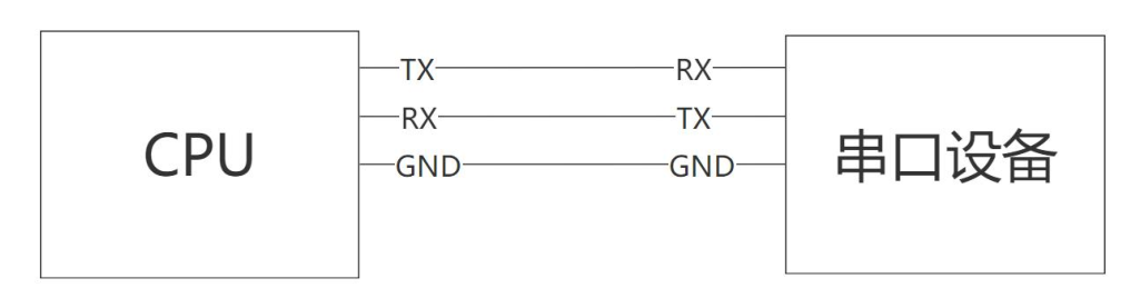
Specifically, typical serial communication only requires 3 wires: ground (GND), transmit (TX), and receive (RX), as shown in the figure below, with one wire for transmitting and one for receiving.No clock line。
Baud rate
Baud rate is a key parameter in serial communication, which refers to the number of symbols (pulses) transmitted per second, i.e., the symbol rate.
In a digital channel, a pulse signal is a symbol, as shown in the figure below. The symbol rate indicates how many symbols or pulse signals can be sent in 1 second.

Both communicating parties must set the same baud rate to ensure data can be transmitted correctly. Common standard baud rates such as 9600, 115200, etc., usually meet the needs of most applications.
However, in specific cases, it may be necessary to set a non-standard baud rate, in which case it is necessary to ensure that all communication devices can support and correctly configure this baud rate.
For baud rate settings higher than 1.5 Mbps, it may be necessary to implement them through fractional or integer division of the clock.
If the required baud rate cannot be achieved through frequency division, it may be necessary to adjust the PLL (Phase-Locked Loop) settings. Adjusting the PLL carries certain risks because it may affect other modules of the device.
bit raterefers toThe number of bits transmitted per unit time, usually expressed in bps (bit per second), the unit is bit/s. Compared with that,Baud ratethenThe number of symbols or pulse signals transmitted per second.. The relationship between the two can be expressed by the formula:Bit rate = Baud rate * log2(M), where M represents the amount of information carried by each symbol.
A symbol is actually a pulse signal, which may carry 1 bit, 2 bits, or more bits of data, depending on the specific implementation of the communication system.In a binary system, the bit rate equals the baud rate, because each symbol carries exactly 1 bit of information.。
For example: if the baud rate of a serial port is 9600, then in a binary system, how many bytes can be transmitted in one second?
One byte equals 8 bits, that is, 8 high/low level changes, because in a binary system, the bit rate equals the baud rate. Therefore, the number of bytes that can be transmitted in one second is 9600/8=1200 bytes.
Serial Port Communication Protocol
Data Stream Structure
In serial communication, in addition to the baud rate, the structure of the data stream is also crucial.
Each frame of data includes 11 bits (when including the parity bit):
- 1 start bit
- 8 data bits
- 1 parity bit (optional)
- 1 stop bit
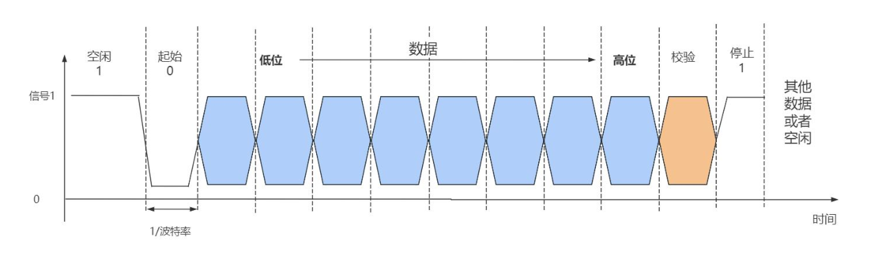
Start bit: Indicates the start of data transmission. The idle state on the data line is 1. Pulling the line from high level (idle state) to low level indicates the start of data transmission.
Data bits: Refers to the number of data bits in each byte, usually 7 or 8 bits.
Parity bit: Used to verify the accuracy of transmitted data. Its types include odd parity, even parity, space parity, and mark parity.
Odd parity: The total number of 1s in the data bits and the parity bit is odd. When the number of 1s in the data bits is even, the parity bit is 1; otherwise, the parity bit is 0.
Even parity: The total number of 1s in the data bits and parity bit is even. When the number of 1s in the data bits is even, the parity bit is 0; otherwise, the parity bit is 1.
0 parity (space parity): The parity bit is always 0; if it is 1, it indicates an error.
1 parity (mark parity): The parity bit is always 1; if it is 0, it indicates an error.
Stop bit: Refers to the number of bits sent after each data byte transmission, usually 1 or 2 bits.
Timing waveform analysis
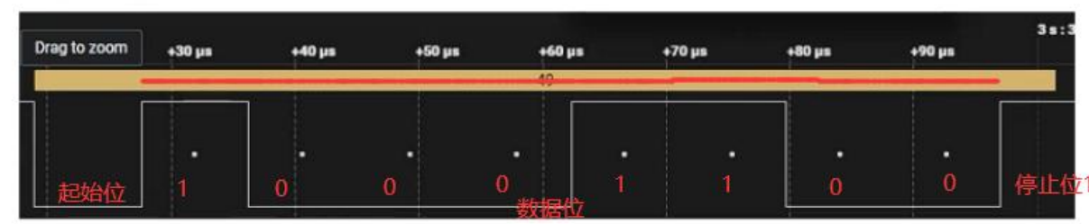
whenThe data line is at a high level when idle, and duringdata transmission, it will be pulled low, the first pulse in the figure corresponds to the start bit. Following it are 8 data bits, which are transmitted in least significant bit (LSB) first order.
For example, the data bits “00110001” converted to hexadecimal is 0x31, which is 49 in decimal. In ASCII, 49 corresponds to the character ‘1’, so the transmitted data is the character ‘1’. After data transmission is complete, the bus is pulled high.
Types of serial port communication interfaces
UART only specifies the timing of transmission and reception, that is, “send the start bit first, then data bits, parity bit, and finally the stop bit”. It only specifies high and low levels, but does not specify how many volts the high level is or how many volts the low level is.
Common interface levels for serial ports include TTL、RS-232、RS-485、RS-422, andEach interface usually requires a corresponding level conversion chip。When directly using the serial port interface from the processor, it is usually TTL level。
However, different models or suppliers of processors may have level differences, which means that in some cases devices cannot be connected directly. Therefore, appropriate level conversion must be performed to ensure normal communication. A general comparison of serial port interface levels is shown in the following table:
| Level standard | Logic level definition | Typical high/low level voltage | Signal type | Maximum transmission distance | Main Features |
|---|---|---|---|---|---|
| TTL | 0 = Low level 1 = High level | Low level: 0 V; High level: 1.8 V / 2.5 V / 3.3 V / 5 V (depending on supply voltage) | Single-ended signal | A few meters (typically ≤ 2–5 m) | Short-distance communication on-board or between boards; directly compatible with MCUs, sensors, etc.; weak anti-interference capability; not suitable for long distances. |
| RS-232 | 0 = positive voltage(+3 V ~ +15 V) 1 = negative voltage(-3 V ~ -15 V) | Logic 0 (space): +3 V ~ +15 V; Logic 1 (mark): -3 V ~ -15 V; commonly ±12 V | Single-ended (but uses positive and negative voltages) | About 15–50 meters (lower speed allows longer distance) | Supports point-to-point communication; stronger anti-interference capability than TTL; requires level-shifting chips (e.g., MAX232); gradually being replaced by USB, etc. |
| RS-422 | Differential signal: 1 = A < B(-2 V ~ -6 V) 0 = A > B(+2 V ~ +6 V) | Differential voltage: ±2 V ~ ±6 V | Differential signal(Full-duplex, 4-wire) | Maximum approx. 1200 meters(@ 100 kbps) | Supports full-duplex communication; strong common-mode interference rejection; suitable for industrial environments; typically 1 transmitter, multiple receivers. |
| RS-485 | Differential signal: 1 = A < B(-1.5 V ~ -5 V) 0 = A > B(+1.5 V ~ +5 V) | Differential voltage: ≥ ±1.5 V (typical ±2 V ~ ±5 V) | Differential signal(Half-duplex or full-duplex, 2 or 4 wires) | Maximum approx. 1200 meters(at 100 kbps) (theoretically up to 1219 meters) | Supports multipoint communication (up to 32~256 nodes), widely used in industrial buses (such as Modbus), strong anti-interference, suitable for long-distance, noisy environments |
RS232 interface
RS232(Recommended Standard 232) The protocol is a serial communication standard established by the Electronic Industries Association (EIA) of the United States in 1970. This standardunified the connector and pin definitions for serial port communication, as shown in the figure below, and clearly specified the level standards for each connector pin.

DB9 pin description
DB9 is a common serial port connector, typically used for RS-232 serial communication and other serial communication applications. It contains 9 pins, each with a specific function. The following is the pin description of the DB9 connector:
- Pin 1 - DCD (Data Carrier Detect): Data Carrier Detect. Indicates whether the remote device is ready for communication.
- Pin 2 - RXD (Receive Data): Receive Data. Receives data stream from the remote device.
- Pin 3 - TXD (Transmit Data): Transmit Data. Sends data stream to the remote device.
- Pin 4 - DTR (Data Terminal Ready): Data Terminal Ready. Indicates that the data terminal equipment (such as a computer) is ready for communication.
- Pin 5 - GND (Ground): Ground. Electrical grounding, used for circuit reference and shielding.
- Pin 6 - DSR (Data Set Ready): Data Set Ready. Indicates that the remote device is ready to receive and transmit data.
- Pin 7 - RTS (Request to Send): Request to Send. The sender uses this signal to request to start sending data.
- Pin 8 - CTS (Clear to Send): Clear to Send. The receiver uses this signal to indicate readiness to receive data.
- Pin 9 - RI (Ring Indicator): Ring Indicator. Indicates that the remote device has sent a ring signal.
RS232 is essentially also a serial port protocol, the same as the serial port protocol. However, it specifies the physical interface and level characteristics of the serial port, so it differs at the hardware level, but there is no difference in software programming and implementation of serial communication.
Level characteristics
The electrical signals at the RS232 receiving and transmitting ends are
relative to the common ground(GND)voltage signals 。- In the RS232 standard,a voltage difference between +3V and +15V is defined as logic ‘0’, and during A voltage between -3V and -15V represents logic ‘1’. The case where the voltage difference is between -3V and +3V is undefined.
- Usually, in practical applications, it is desired that the absolute value of the voltage difference be between 5V and 15V to ensure reliable signal transmission.
- When sending data, the transmitter driver outputs a positive voltage signal of +5V to +15V to represent logic ‘0’, and a negative voltage signal of -5V to -15V to represent logic ‘1’.
- When receiving data, as long as an electrical signal greater than 3V is detected, it is considered a valid signal.
The RS232 interface has relatively high current capability during sending and receiving, and can handle relatively large current loads, which makes it suitable for long-distance communication and connecting external devices.
RS232 signals have high anti-interference capability, can operate stably in industrial environments, and are not easily affected by electromagnetic interference.
RS232 includes the following signal lines:
- Transmit line (Tx)
- Receive line (Rx)
- Ground line (Ground)
- Data Terminal Ready (DTR)
- Data Set Ready (DSR)
- Request to Send (RTS)
- Clear to Send (CTS)
- Data Carrier Detect (DCD)
RS232 supports various baud rates, usually from low rates to higher rates, with a maximum of several hundred kilobits per second (kbps).
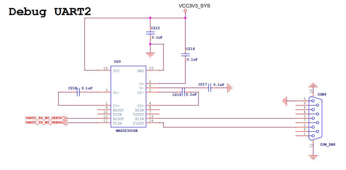
On the iTOP-RK3568 development board, the debug serial port uses the MAX3232 chip to convert TTL levels to 232 levels. The schematic diagram of the debug serial port is shown in the figure below.
RS485 Interface
The RS485 standard was jointly developed by the Telecommunications Industry Association (TIA) and the Electronic Industries Alliance (EIA). The main purpose of this standard is
Features and Advantages
- Long-distance communication capability: RS485 can achieve communication distances up to 1200 meters under ideal conditions, making it suitable for applications requiring long-distance data transmission.
- Strong anti-interference capability: Due to the use of differential signal transmission, RS485 can effectively resist electromagnetic interference (EMI) and radio frequency interference (RFI), ensuring the stability and reliability of data transmission.
- Multi-station capability: RS485 supports multiple devices (up to 32) communicating on the same bus, and each device can independently send and receive data, enabling flexible network networking.
- Wide application: RS485 is widely used in industrial automation control systems, building automation, smart home systems, power system monitoring, and other fields, meeting the requirements for long-distance, high-speed, and reliable communication.
Level characteristics
The level characteristics of RS485 are as follows:
- Differential signal transmission: RS485 uses differential signals for data transmission, that is, the data signal is represented by the voltage difference between two signal lines (usually marked as A and B lines). This differential signal transmission method gives RS485 good anti-interference capability and long-distance transmission capability.
- Voltage range:
- Logic ‘1’ is represented by a voltage difference of +(2~6)V between the two lines.;
- Logic ‘0’ is represented by a voltage difference of -(2~6)V between the two lines.。
- Interface signal level ratio RS232 reduced, making it less likely to damage the interface circuit chip, and This level is TTL level compatible , and can be easily connected to TTL circuits.
- Current capability: The RS485 transmitter has strong driving capability and can drive long communication lines and multiple receivers. The receiver can handle large input currents to ensure reliable signal reception.
- Electrical characteristics: RS485 supportsmultiple devices(up to 32 piece)communicating on the same busSupports communication distances up to 1200 meters, and even longer in specific cases.
Used on the iTOP-RK3568 development board SIT3485E chipConverts TTL levels to 485 levels, as shown in the schematic diagram below:

It can be seen that the RS485 interface of the RK3568 development board is actually serial port 7 converted via the SIT3485E chip.
SIT3485E chip

SIT3485E is a wide power supply 3.0V~5.5V, bus port ESD level up to 15KV HBM or above, bus withstand voltage range up to ±15V,half-duplex、low power consumption,an RS-485 transceiver whose functions fully meet the requirements of the TIA/EIA-485 standard。
SIT3485E includesa driveranda receiver, both of which can beindependently enabled and disabledWhen both are disabled, the driver and receiver both output high impedance.
SIT3485E has 1/8 load, allowing 256 SIT3485E transceivers to be connected on the same communication bus. It can achieve error-free data transmission up to 12Mbps.
SIT3485E operating voltage range is 3.0~5.5 V, with fail-safe, current limiting protection, overvoltage protection and other functions.

| Pin number | Pin name | Pin function |
|---|---|---|
| 1 | RO | Receiver output. When /RE is low, if A-B ≥ -10mV, RO outputs high; if A-B ≤ -200mV, RO outputs low. |
| 2 | /RE | Receiver output enable control. When /RE is connected low, the receiver output is enabled and RO output is active; when /RE is connected high, the receiver output is disabled and RO is high-impedance; when /RE is high and DE is low, the device enters low-power shutdown mode. |
| 3 | DE | Driver output enable control. When DE is high, the driver output is active; when DE is low, the output is high-impedance; when /RE is high and DE is low, the device enters low-power shutdown mode. |
| 4 | DI | DI driver input. When DE is high, a low level on DI makes the driver non-inverting output A low and the inverting output B high; a high level on DI makes the non-inverting output high and the inverting output low. |
| 5 | GND | Ground |
| 6 | A | Receiver non-inverting input and driver non-inverting output |
| 7 | B | Receiver inverting input and driver inverting output |
| 8 | VCC | Power supply |
From the pin definition diagram:
- The RO pin is the receiver output, connected to UART7 in the schematic._RX_M1 pin.
- The DI pin is the DI driver input pin, connected to UART7 in the schematic._TX_M1 pin.
- The A pin is the receiver non-inverting input and driver non-inverting output.
- The B pin is the receiver inverting input and driver inverting output. A and B form the RS485 differential pair.
- RE The pin is the receiver output enable control pin.
- When /RE is connected low, the receiver output is enabled and RO output is active.
- When /RE is connected high, the receiver output is disabled and RO is high-impedance.
- The DE pin is the driver output enable control pin. When DE is high, the driver output is active; when DE is low, the output is high-impedance.
- REWhen /RE is high and DE is low, the device enters low-power mode.
In simple terms:
- REWhen /RE is low, RO output is active. Conversely, RO is high-impedance, i.e., inactive. RO is connected to UART7_RX_M1,UART7_RX_M1 is the receive pin of the serial port. Therefore, when /RE is low, the serial port can receive data; otherwise, the serial port cannot receive data.
- When DE is high, DI is active, and DI is connected to UART7._TX_M1,UART7_TX_M1 is the serial port transmit pin. Therefore, when DE is high, a low level on DI causes the driver non-inverting output A to output low and the driver inverting output B to output high, so the serial port can send data; otherwise, the serial port cannot send data.
RE It is exactly opposite to the active level of DE., and because 485 ishalf-duplex, it cannot transmit and receive simultaneously. ThereforeRE /RE and DE definitely cannot be enabled at the same time,that is,RE /RE and DE must have the same level. In this way,REWhen /RE is enabled, it is equivalent to DE being disabled, so these two pins are connected together.
This makes it very clear. If GPIO0_C6 outputs a low level,RE /RE and DE are low,RE When /RE is low, the serial port can receive data; when DE is low, the serial port cannot send data.
If GPIO0_C6 outputs a high level,RE/RE and DE are high,RE When /RE is high, the serial port cannot receive data; when DE is high, the serial port can send data.
That is to say, we need to use GPIO0_The high/low level of pin C6 controls whether RS485 transmits or receives. Therefore, we need to write a driver to achieve this purpose. The source code provided by Xunwei is configured by default with a driver to control GPIO0_C6。
Auto-transceiver 485 circuit
In addition to software control, automatic switching can also be implemented through hardware to achieve RS485 automatic transceiving. Software-controlled transmission and reception has a certain time difference. To reduce this time difference, the baseboard schematic of the Xunwei development board has been optimized to be compatible with hardware-implemented automatic transceiving. The specific modification method is to remove R295 and solder all components marked as DNP in the figure below.

- When UART_TX_When M1 is high, the base of Q17 is also high, causing Q17 to conduct,RE /RE and DE are low, so the serial port is in receive data mode.
- When UART_TX_When M1 is at low level, the base of Q17 is at low level, causing Q17 to be cut off.RE And DE is at high level, the serial port is in data transmission mode. Because UART_TX_M1 is at high level when idle, indicating that the serial port is in the receiving data state; when UART_TX_When M1 is pulled low, the serial port is in the data transmission state.
Since UART_TX_M1 high level indicates receive mode, so when sending 1, it is also high level. This way the chip will always be in receive mode, making it impossible to send 1, right?
When the adapter chip is in receive mode, both pins A and B will be in a high-impedance state.。
High impedance state means very large resistance, almost equivalent to an open circuit.At this time, A is pulled high by the pull-up resistor, and B is pulled low by the pull-down resistor.。
Therefore,A high, B low represents 1 in communication.. Through this “reception mode”, we cleverly sent out the “1”.
This optimization eliminates an RS485 transceiver control IO, allowing RS485 to be used entirely as a serial port, which facilitates driver development.
Serial Port Subsystem Framework
The serial subsystem framework is a modular framework in the Linux kernel specifically for handling serial devices, as shown in the framework diagram below.
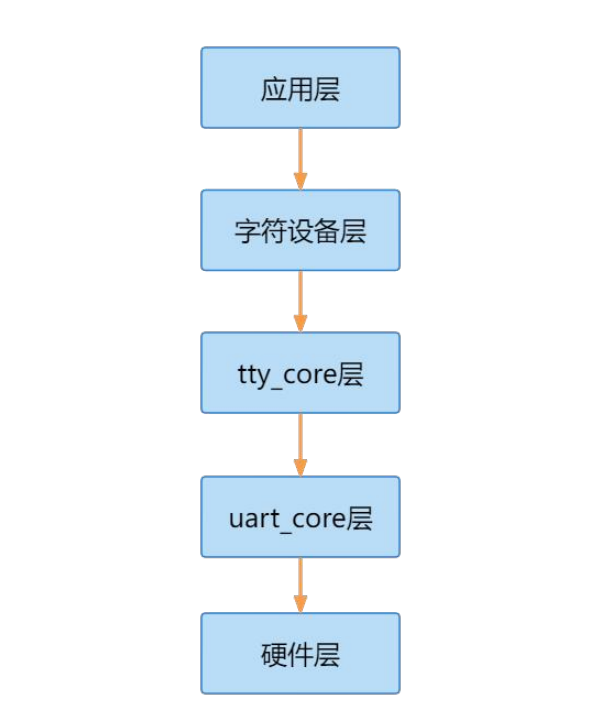
- Application layer: Located at the topmost layer, it is the interface between user-space applications and kernel space in the serial port subsystem. The application layer includes user-space serial port applications, such as the serial communication tool minicom, etc.
- Character device layer: Located below the application layer, it is responsible for passing serial port read/write requests from user space to the tty_core layer in kernel space. The character device layer treats the serial port device as a special character device and operates through the character device interface.
- tty_core layer: Located below the character device layer, it is the core module in the Linux kernel for managing serial port devices. It handles the basic functions of serial port devices, such as data transmission, control, buffer management, etc. The tty_core layer is independent of specific serial port hardware and is a general processing layer for serial port devices.
- UART core layer: located at tty_Below the core layer, it provides the low-level driver interface for serial port devices, responsible for communicating with the specific serial port hardware. uart_The core layer is responsible for controlling low-level operations such as serial port data transmission and reception, interrupt handling, and clock management.
- Hardware layer: Located at the bottom layer, it is the part of the serial port subsystem related to specific hardware. The hardware layer includes the driver for the serial port hardware, communicates with the specific serial port controller, and implements low-level control and operation of the hardware.
Configure serial port driver
In the SDK kernel source code provided by Rockchip, the serial port driver uses the 8250 generic serial port driver. The following are the main driver files
drivers/tty/serial/8250/8250_core.c8250 serial port driver coredrivers/tty/serial/8250/8250_dw.cSynopsis DesignWare 8250 serial port driverdrivers/tty/serial/8250/8250_dma.c8250 serial port DMA driverdrivers/tty/serial/8250/8250_port.c8250 serial port operationsdrivers/tty/serial/8250/8250_early.c8250 serial port early console driver
Select the driver in make menuconfig
12 | Device Driver / Character devices / Serial drivers [*] Console on 8250/16550 and compatible serial port |
In the device tree of the SDK source code provided by Xunwei, serial port 9 is enabled by default. Openarch/arm64/boot/dts/rockchip/rk3568.dtsithe device tree file, the device tree node of the serial port 9 controller is as follows:
12345678910111213 | uart9: serial@fe6d0000 { compatible = "rockchip,rk3568-uart", "snps,dw-apb-uart"; reg = <0x0 0xfe6d0000 0x0 0x100>; interrupts = <GIC_SPI 125 IRQ_TYPE_LEVEL_HIGH>; clocks = <&cru SCLK_UART9>, <&cru PCLK_UART9>; clock-names = "baudclk", "apb_pclk"; reg-shift = <2>; reg-io-width = <4>; dmas = <&dmac0 18>, <&dmac0 19>; pinctrl-names = "default"; pinctrl-0 = <&uart9m0_xfer>; status = "disabled";}; |
compatible: Specifies the compatible string of the device, indicating that this serial port device is compatible withrockchip,rk3568-uartandsnps,dw-apb-uarttwo types of serial port controllers. This helps the device tree bind the corresponding driver.reg: Specifies the address and size of the serial port device. 0xfe6d0000 is the base address of the serial port device, and 0x100 indicates the size of the address space.interrupts: Specifies the interrupt information of the serial port device, including the interrupt type and interrupt number.clocks: Specifies the clock sources used by the serial port device, including the baud rate clock and the APB clock.clock-names: Specifies the name of the clock source, used to match the specific configuration of the clock source.reg-shift: Indicates the bit width of the address offset, that is, whether the offset of each register is in bytes or words.reg-io-width: Indicates the access width of the device address and data. Here, 4 means a 4-byte width.dmas: Specifies the DMA controller and DMA channel number used by the serial port device for DMA operations of data transmission.dma-names: The optional values aretxEnable tx dmarxEnable rx dma!txDisable tx dma!rxDisable RX DMA
pinctrl-namesandpinctrl-0: Used for pin control of serial port devices, to configure and manage the pin settings of serial port devices. The optional parameters are as follows:&uart9m0_xferConfigure TX and RX pins as iomux group 0&uart9m1_xferConfigure TX and RX pins as iomux group 1&uart9m0_ctsnand&uart9m0_rtsnConfigure hardware auto flow control CTS and RTS pins as iomux group 0&uart9m1_ctsnand&uart9m1_rtsnConfigure hardware auto flow control CTS and RTS pins as iomux group 1
status: Indicates the status of the serial port device. Here, “disabled” means the device is currently disabled. If set to “okay”, it means the device is enabled.
uart_driver registration process analysis
UART-related underlying structures
The relationships between UART-related underlying structures are as follows:
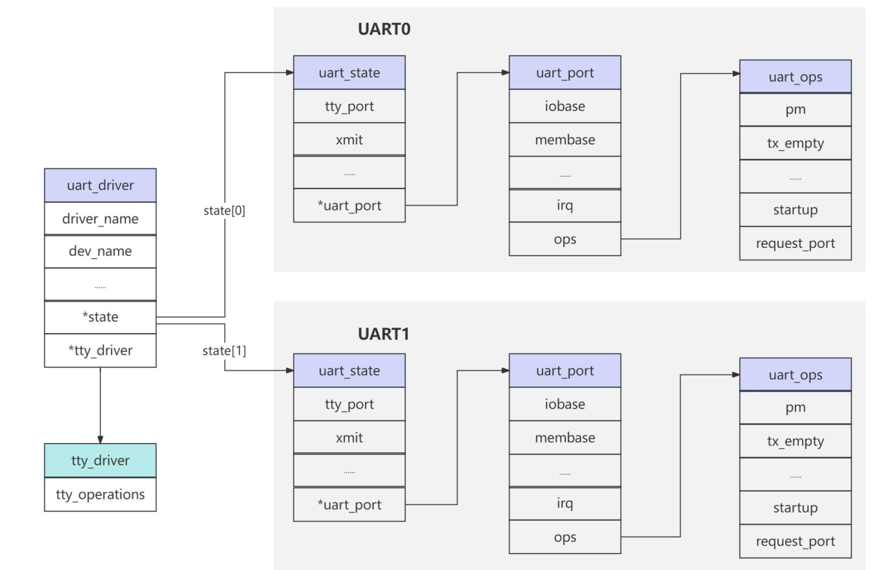
struct uart_driver
uart_driverThe structure represents the UART driver,uart_driverdefined ininclude/linux/serial_core.hIn the file, the content is as follows:
12345678910111213141516 | struct uart_driver { struct module *owner;// Module owner const char *driver_name;// Driver name const char *dev_name;// device name int major;// Major device number assigned to the device int minor;// Minor device number assigned to the device int nr;// Device unique identifier struct console *cons;// Pointer to the console /* * these are private; the low level driver should not * touch these; they should be initialised to NULL */ struct uart_state *state;// Pointer to the UART driver state struct tty_driver *tty_driver;// Pointer to the TTY driver}; |
struct uart_driverEncapsulatestty_driver, so that the underlying UART driver does not need to care abouttty_driver。
struct uart_port
uart_port is an abstraction for a serial port, defined ininclude/linux/serial_core.h, the content is as follows:
123456789101112131415161718192021222324252627282930313233343536373839404142434445464748495051525354555657585960616263646566676869707172737475767778798081828384858687888990919293949596979899100101102103104105106107108109110111112113114115116117118119120121122123124125126127128129130131132133134135136137138139140141142143144145146147148149150151152153154155 | struct uart_port { spinlock_t lock; /* port lock */ unsigned long iobase; /* in/out[bwl] *//* IO port base address (physical) */ unsigned char __iomem *membase; /* read/write[bwl] *//* IO memory base address (virtual) */ unsigned int (*serial_in)(struct uart_port *, int); void (*serial_out)(struct uart_port *, int, int); void (*set_termios)(struct uart_port *, struct ktermios *new, struct ktermios *old); void (*set_ldisc)(struct uart_port *, struct ktermios *); unsigned int (*get_mctrl)(struct uart_port *); void (*set_mctrl)(struct uart_port *, unsigned int); unsigned int (*get_divisor)(struct uart_port *, unsigned int baud, unsigned int *frac); void (*set_divisor)(struct uart_port *, unsigned int baud, unsigned int quot, unsigned int quot_frac); int (*startup)(struct uart_port *port); void (*shutdown)(struct uart_port *port); void (*throttle)(struct uart_port *port); void (*unthrottle)(struct uart_port *port); int (*handle_irq)(struct uart_port *); void (*pm)(struct uart_port *, unsigned int state, unsigned int old); void (*handle_break)(struct uart_port *); int (*rs485_config)(struct uart_port *, struct serial_rs485 *rs485); int (*iso7816_config)(struct uart_port *, struct serial_iso7816 *iso7816); unsigned int irq; /* irq number */ unsigned long irqflags; /* irq flags */ unsigned int uartclk; /* base uart clock */ unsigned int fifosize; /* tx fifo size */ unsigned char x_char; /* xon/xoff char */ unsigned char regshift; /* reg offset shift */ unsigned char iotype; /* io access style */ unsigned char quirks; /* internal quirks */ /* quirks must be updated while holding port mutex */ unsigned int read_status_mask; /* driver specific */ unsigned int ignore_status_mask; /* driver specific */ struct uart_state *state; /* pointer to parent state */ struct uart_icount icount; /* statistics */ struct console *cons; /* struct console, if any */ /* flags must be updated while holding port mutex */ upf_t flags; /* * These flags must be equivalent to the flags defined in * include/uapi/linux/tty_flags.h which are the userspace definitions * assigned from the serial_struct flags in uart_set_info() * [for bit definitions in the UPF_CHANGE_MASK] * * Bits [0..UPF_LAST_USER] are userspace defined/visible/changeable * The remaining bits are serial-core specific and not modifiable by * userspace. *//* Port has hardware-assisted h/w flow control *//* Port has hardware-assisted s/w flow control *//* The exact UART type is known and should not be probed. */ /* * Must hold termios_rwsem, port mutex and port lock to change; * can hold any one lock to read. */ upstat_t status; int hw_stopped; /* sw-assisted CTS flow state */ unsigned int mctrl; /* current modem ctrl settings */ unsigned int timeout; /* character-based timeout */ unsigned int type; /* port type */ const struct uart_ops *ops; unsigned int custom_divisor; unsigned int line; /* port index */ unsigned int minor; resource_size_t mapbase; /* for ioremap */ resource_size_t mapsize; struct device *dev; /* parent device */ unsigned long sysrq; /* sysrq timeout */ unsigned int sysrq_ch; /* char for sysrq */ unsigned char has_sysrq; unsigned char sysrq_seq; /* index in sysrq_toggle_seq */ unsigned char hub6; /* this should be in the 8250 driver */ unsigned char suspended; unsigned char console_reinit; const char *name; /* port name */ struct attribute_group *attr_group; /* port specific attributes */ const struct attribute_group **tty_groups; /* all attributes (serial core use only) */ struct serial_rs485 rs485; struct gpio_desc *rs485_term_gpio; /* enable RS485 bus termination */ struct serial_iso7816 iso7816; void *private_data; /* generic platform data pointer */}; |
struct uart_state
struct uart_statedefined ininclude/linux/serial_core.h, which internally contains atty_portmember variable of type, usually used to represent UART driver state information. Throughuart_driverThe state member pointer in the structure can access and manipulate data related to the UART device state.
1234567891011121314 | /* * This is the state information which is persistent across opens. */struct uart_state { struct tty_port port; enum uart_pm_state pm_state; struct circ_buf xmit; atomic_t refcount; wait_queue_head_t remove_wait; struct uart_port *uart_port;}; |
struct uart_ops
Structuart_opsContains a series of function pointers, which define the interface for operating the UART port. Each function pointer corresponds to a specific operation, such as sending data, setting control signals, starting or stopping transmission, etc.
Through theuart_opsstructure, upper-level applications or drivers can call these function pointers to operate the UART port, enabling data transmission and control operations.
1234567891011121314151617181920212223242526272829303132333435363738394041424344454647484950 | /* * This structure describes all the operations that can be done on the * physical hardware. See Documentation/driver-api/serial/driver.rst for details. */struct uart_ops { unsigned int (*tx_empty)(struct uart_port *);// Function pointer to check whether the transmit buffer is empty void (*set_mctrl)(struct uart_port *, unsigned int mctrl);// Function pointer to set modem control signals unsigned int (*get_mctrl)(struct uart_port *);// Function pointer to get modem control signals void (*stop_tx)(struct uart_port *);// Function pointer to stop sending void (*start_tx)(struct uart_port *);// Function pointer to start sending void (*throttle)(struct uart_port *);// Function pointer to throttle void (*unthrottle)(struct uart_port *);// Function pointer to unthrottle void (*send_xchar)(struct uart_port *, char ch);// Function pointer to send special characters void (*stop_rx)(struct uart_port *);// Function pointer to stop receiving void (*enable_ms)(struct uart_port *);// Function pointer to enable RTS/CTS (hardware flow control) void (*break_ctl)(struct uart_port *, int ctl);// Function pointer to control sending BREAK signal int (*startup)(struct uart_port *);// Function pointer to start void (*shutdown)(struct uart_port *);// Function pointer to shut down void (*flush_buffer)(struct uart_port *);// Function pointer to flush buffer void (*set_termios)(struct uart_port *, struct ktermios *new, struct ktermios *old);// Function pointer to set terminal information void (*set_ldisc)(struct uart_port *, struct ktermios *);// Function pointer to set line discipline void (*pm)(struct uart_port *, unsigned int state, unsigned int oldstate);// Function pointer for power management /* * Return a string describing the type of the port */ const char *(*type)(struct uart_port *);// Function pointer to get port type /* * Release IO and memory resources used by the port. * This includes iounmap if necessary. */ void (*release_port)(struct uart_port *);// Function pointer to release port /* * Request IO and memory resources used by the port. * This includes iomapping the port if necessary. */ int (*request_port)(struct uart_port *);// Request port function pointer void (*config_port)(struct uart_port *, int);// Configure port function pointer int (*verify_port)(struct uart_port *, struct serial_struct *);// Validate port function pointer int (*ioctl)(struct uart_port *, unsigned int, unsigned long);// Control operation function pointer int (*poll_init)(struct uart_port *);// Polling initialization function pointer void (*poll_put_char)(struct uart_port *, unsigned char);// Polling send character function pointer int (*poll_get_char)(struct uart_port *);// Polling get character function pointer}; |
uart_driver registration analysis
drivers/tty/serial/8250/8250_core.cThe functions in the file are mainly related to the core functionality of the 8250 series UART driver. This file implements the core operations of the 8250 serial communication device, including initialization, configuration, interrupt handling, data transmission, and other functions.
serial8250_init()
1234567891011121314151617181920212223242526272829303132333435363738394041424344454647484950515253545556575859606162 | static int __init serial8250_init(void){ int ret; if (nr_uarts == 0)// Check whether a UART port is defined; if not, return the -ENODEV error. return -ENODEV; // Initialize 8250/16550 serial port serial8250_isa_init_ports(); // Print serial driver information, including the number of ports and IRQ sharing status. pr_info("Serial: 8250/16550 driver, %d ports, IRQ sharing %sabled\n", nr_uarts, share_irqs ? "en" : "dis"); // If it is the SPARC architecture, register the minor device number of the serial device. ret = sunserial_register_minors(&serial8250_reg, UART_NR); // Otherwise, register the UART driver on the current platform. serial8250_reg.nr = UART_NR; ret = uart_register_driver(&serial8250_reg); if (ret) goto out; ret = serial8250_pnp_init();// Initialize PNP device (if present) if (ret) goto unreg_uart_drv; // Allocate an ISA platform device structure and register it serial8250_isa_devs = platform_device_alloc("serial8250", PLAT8250_DEV_LEGACY); if (!serial8250_isa_devs) { ret = -ENOMEM; goto unreg_pnp; } // Add the platform device to the system ret = platform_device_add(serial8250_isa_devs); if (ret) goto put_dev; // Register serial port serial8250_register_ports(&serial8250_reg, &serial8250_isa_devs->dev); // Register the platform driver ret = platform_driver_register(&serial8250_isa_driver); if (ret == 0) goto out; // If registration fails, delete the added ISA platform device. platform_device_del(serial8250_isa_devs);put_dev: platform_device_put(serial8250_isa_devs);unreg_pnp: serial8250_pnp_exit();// Release PNP device on exitunreg_uart_drv: sunserial_unregister_minors(&serial8250_reg, UART_NR);// If it is the SPARC architecture, unregister the minor device number of the serial device. uart_unregister_driver(&serial8250_reg);// Otherwise, unregister the UART driver on the current platform.out: return ret;// Return the initialization result} |
Initialize 8250 serial port
serial8250_isa_init_ports()
serial8250_init(void)The function is mainly responsible for initializing and registering the 8250/16550 serial port device driver at system startup, where line 10serial8250_isa_init_ports()The function initializes the 8250 serial port, as shown below:
1234567891011121314151617181920212223242526272829303132333435363738394041424344454647484950515253545556575859606162636465666768697071 | static void __init serial8250_isa_init_ports(void){ struct uart_8250_port *up;// UART 8250 port structure pointer static int first = 1;// Static variable used to mark whether it is the first initialization int i, irqflag = 0;// Loop variable and IRQ flag bit are initialized to 0 if (!first)// If it is not the first initialization, return directly to avoid repeated initialization return; first = 0;// Mark as not the first initialization // If the number of UART ports defined by the system is greater than the maximum number supported by the hardware, limit it to the maximum supported number if (nr_uarts > UART_NR) nr_uarts = UART_NR; // Iterate through all defined UART ports and initialize each port for (i = 0; i < nr_uarts; i++) { struct uart_8250_port *up = &serial8250_ports[i];// Get the pointer to the i-th UART port structure struct uart_port *port = &up->port;// Get the generic UART port structure of the port port->line = i;// Set the logical line number of the UART port serial8250_init_port(up);// Initialize the UART port // If base_ops is not set yet, use the current port's operation functions as the base operation functions if (!base_ops) base_ops = port->ops; port->ops = &univ8250_port_ops;// Set the UART port's operation functions to univ8250_port_ops // Initialize timer timer_setup(&up->timer, serial8250_timeout, 0); // Set the UART port's driver operation functions to univ8250_driver_ops up->ops = &univ8250_driver_ops; /* * ALPHA_KLUDGE_MCR needs to be killed. */ up->mcr_mask = ~ALPHA_KLUDGE_MCR;// Set the UART port's MCR mask bits to mask ALPHA_KLUDGE_MCR up->mcr_force = ALPHA_KLUDGE_MCR;// Set the UART port's MCR force bits to ALPHA_KLUDGE_MCR serial8250_set_defaults(up);// Set the default parameters of the UART port } /* chain base port ops to support Remote Supervisor Adapter */ univ8250_port_ops = *base_ops;// Chain the base port operations to support the Remote Supervisor Adapter (RSA) univ8250_rsa_support(&univ8250_port_ops); // If the shared IRQ flag is set, set the IRQ flag bit if (share_irqs) irqflag = IRQF_SHARED; // Iterate through the old serial port array and initialize the corresponding UART ports for (i = 0, up = serial8250_ports; i < ARRAY_SIZE(old_serial_port) && i < nr_uarts; i++, up++) { struct uart_port *port = &up->port; // Set the UART port's I/O base address, IRQ, IRQ flags, clock frequency, flags, hub6, and other parameters port->iobase = old_serial_port[i].port; port->irq = irq_canonicalize(old_serial_port[i].irq);// Normalize the IRQ port->irqflags = 0; port->uartclk = old_serial_port[i].baud_base * 16;// Set the UART clock frequency port->flags = old_serial_port[i].flags;// Set UART port flags port->hub6 = 0; port->membase = old_serial_port[i].iomem_base; port->iotype = old_serial_port[i].io_type; port->regshift = old_serial_port[i].iomem_reg_shift; port->irqflags |= irqflag;// Set IRQ flag bits // If an ISA configuration function is defined, call the configuration function to perform additional configuration if (serial8250_isa_config != NULL) serial8250_isa_config(i, &up->port, &up->capabilities); }} |
serial8250_init_port()
Executed at line 21 aboveserial8250_init_portFunction:
123456789101112131415 | /** Initialize UART 8250 Port function。*/void serial8250_init_port(struct uart_8250_port *up){ struct uart_port *port = &up->port;// Get the UART 8250 port structure spin_lock_init(&port->lock);// Initialize the port lock port->pm = NULL; port->ops = &serial8250_pops;// Set the port operation function to serial8250_pops port->has_sysrq = IS_ENABLED(CONFIG_SERIAL_8250_CONSOLE); up->cur_iotype = 0xFF;// Set the current port's I/O type to 0xFF}EXPORT_SYMBOL_GPL(serial8250_init_port); |
serial8250_popsAs follows:
12345678910111213141516171819202122232425262728 | static const struct uart_ops serial8250_pops = { .tx_empty = serial8250_tx_empty,// Whether the transmit buffer is empty .set_mctrl = serial8250_set_mctrl, // Set control signals .get_mctrl = serial8250_get_mctrl, // Get control signals .stop_tx = serial8250_stop_tx,// Stop sending .start_tx = serial8250_start_tx,// Start sending .throttle = serial8250_throttle,// Throttle .unthrottle = serial8250_unthrottle,// Unthrottle .stop_rx = serial8250_stop_rx,// Stop receiving .enable_ms = serial8250_enable_ms, // Enable RTS/CTS .break_ctl = serial8250_break_ctl,// Control sending the BREAK signal .startup = serial8250_startup,// Enable .shutdown = serial8250_shutdown, // Shutdown .flush_buffer = serial8250_flush_buffer, .set_termios = serial8250_set_termios, .set_ldisc = serial8250_set_ldisc,// Set terminal parameters .pm = serial8250_pm, // Power management .type = serial8250_type, // Return the port type string .release_port = serial8250_release_port,// Release port resources .request_port = serial8250_request_port,// Request port resources .config_port = serial8250_config_port,// Configure port .verify_port = serial8250_verify_port,// Verify port .poll_get_char = serial8250_get_poll_char,// Get character (for polling) .poll_put_char = serial8250_put_poll_char,// Send character (for polling)}; |
Register UART driver
serial8250_init(void)The function is mainly responsible for initializing and registering the 8250/16550 serial port device driver during system startup, in which theuart_register_driver(&serial8250_reg), viauart_register_driverThe function registers this uart_driver with the system, and the function prototype is as follows
1 | int uart_register_driver(struct uart_driver *uart) |
The meanings of the function parameters and return value are as follows:
- uart: The uart_driver to be registered.
- Return value: 0, success; negative value, failure.
When unregistering the driver, the previously registered one also needs to be unregistereduart_driver, you need to useuart_unregister_driverThe function prototype is as follows:
1 | void uart_unregister_driver(struct uart_driver *uart) |
The meanings of the function parameters and return value are as follows:
- uart: The uart_driver to be unregistered.
- Return value: None
serial8250_init(void)In the functionuart_register_driverThe parameter passed to the function isserial8250_reg
12345678 | static struct uart_driver serial8250_reg = { .owner = THIS_MODULE,// The owner of the module .driver_name = "serial",// Driver name .dev_name = "ttyS",// device name .major = TTY_MAJOR,// major device number .minor = 64,// secondary device number .cons = SERIAL8250_CONSOLE,// Console}; |
uart_register_driver()
uart_register_driverThe function content is as follows, defined in the source codedrivers/tty/serial/serial_core.cMiddle.
1234567891011121314151617181920212223242526272829303132333435363738394041424344454647484950515253545556575859606162636465666768697071727374 | /** * uart_register_driver - register a driver with the uart core layer * @drv: low level driver structure * * Register a uart driver with the core driver. We in turn register * with the tty layer, and initialise the core driver per-port state. * * We have a proc file in /proc/tty/driver which is named after the * normal driver. * * drv->port should be NULL, and the per-port structures should be * registered using uart_add_one_port after this call has succeeded. */int uart_register_driver(struct uart_driver *drv){ struct tty_driver *normal; int i, retval = -ENOMEM; BUG_ON(drv->state);// Check whether the driver status is already occupied /* * Maybe we should be using a slab cache for this, especially if * we have a large number of ports to handle. */ drv->state = kcalloc(drv->nr, sizeof(struct uart_state), GFP_KERNEL);// Allocate memory space for UART state if (!drv->state) goto out; // Allocate tty driver normal = alloc_tty_driver(drv->nr); if (!normal) goto out_kfree; drv->tty_driver = normal; // Set tty driver attributes normal->driver_name = drv->driver_name; normal->name = drv->dev_name; normal->major = drv->major; normal->minor_start = drv->minor; normal->type = TTY_DRIVER_TYPE_SERIAL; normal->subtype = SERIAL_TYPE_NORMAL; normal->init_termios = tty_std_termios; normal->init_termios.c_cflag = B9600 | CS8 | CREAD | HUPCL | CLOCAL; normal->init_termios.c_ispeed = normal->init_termios.c_ospeed = 9600; normal->flags = TTY_DRIVER_REAL_RAW | TTY_DRIVER_DYNAMIC_DEV; normal->driver_state = drv; tty_set_operations(normal, &uart_ops); /* * Initialise the UART state(s). */ for (i = 0; i < drv->nr; i++) {// Iterate over each UART state and initialize the corresponding tty port struct uart_state *state = drv->state + i; struct tty_port *port = &state->port; tty_port_init(port); port->ops = &uart_port_ops; } retval = tty_register_driver(normal);// Register tty driver if (retval >= 0) return retval; // On registration failure, destroy initialized tty ports and free memory for (i = 0; i < drv->nr; i++) tty_port_destroy(&drv->state[i].port); put_tty_driver(normal);out_kfree: kfree(drv->state);out: return retval;} |
uart_register_driverIn the functiontty_set_operations(normal, &uart_ops)The code sets the tty driver’s operation functions, which define operations related to specific devices, such as read/write, control, etc.
123456789101112131415161718192021222324252627282930313233343536 | static const struct tty_operations uart_ops = { .install = uart_install,// Install tty device .open = uart_open,// Open tty device .close = uart_close,// Close tty device .write = uart_write,// Write data to tty device .put_char = uart_put_char,// Write characters to tty device output buffer .flush_chars = uart_flush_chars,// Flush tty device output buffer .write_room = uart_write_room,// Get remaining space size of tty device output buffer .chars_in_buffer= uart_chars_in_buffer, // Get number of characters in tty device input buffer .flush_buffer = uart_flush_buffer,// Flush tty device input buffer .ioctl = uart_ioctl,// Control tty device operations .throttle = uart_throttle,// Control tty device flow control state .unthrottle = uart_unthrottle,// Control tty device flow control state .send_xchar = uart_send_xchar,// Send special characters to tty device .set_termios = uart_set_termios,// Set tty device terminal parameters .set_ldisc = uart_set_ldisc,// Set tty device line discipline .stop = uart_stop,// Stop tty device .start = uart_start,// Start tty device .hangup = uart_hangup,// Close the tty device connection .break_ctl = uart_break_ctl,// Control the transmission interrupt of the tty device .wait_until_sent= uart_wait_until_sent,// Wait for the tty device to finish sending all data .proc_show = uart_proc_show,// Display UART-related proc filesystem information .tiocmget = uart_tiocmget,// Get the modem status of the tty device .tiocmset = uart_tiocmset,// Set the modem status of the tty device .set_serial = uart_set_info_user, .get_serial = uart_get_info_user, .get_icount = uart_get_icount,// Get the counting information of the tty device .poll_init = uart_poll_init,// Initialize the polling mode of the tty device .poll_get_char = uart_poll_get_char,// Get a character from the tty device (polling mode) .poll_put_char = uart_poll_put_char,// Write a character to the tty device (polling mode)}; |
uart_register_driverCalled in the function.tty_register_driverfunction, defined indrivers/tty/tty_io.c
tty_register_driver()
123456789101112131415161718192021222324252627282930313233343536373839404142434445464748495051525354555657585960616263646566676869 | /* * Called by a tty driver to register itself. *//** when tty Called when the driver calls this function to register itself。*/int tty_register_driver(struct tty_driver *driver){ int error; int i; dev_t dev; struct device *d; if (!driver->major) {// If the driver does not specify a major device number, allocate one error = alloc_chrdev_region(&dev, driver->minor_start, driver->num, driver->name); if (!error) { driver->major = MAJOR(dev); driver->minor_start = MINOR(dev); } } else { dev = MKDEV(driver->major, driver->minor_start); error = register_chrdev_region(dev, driver->num, driver->name); } if (error < 0) goto err; // If the driver flag is TTY_DRIVER_DYNAMIC_ALLOC, then dynamically add the tty character device if (driver->flags & TTY_DRIVER_DYNAMIC_ALLOC) { error = tty_cdev_add(driver, dev, 0, driver->num); if (error) goto err_unreg_char; } mutex_lock(&tty_mutex); // Add the driver to the tty driver list list_add(&driver->tty_drivers, &tty_drivers); mutex_unlock(&tty_mutex); // If the driver flag is not set to TTY_DRIVER_DYNAMIC_DEV, then register the tty device if (!(driver->flags & TTY_DRIVER_DYNAMIC_DEV)) { for (i = 0; i < driver->num; i++) { d = tty_register_device(driver, i, NULL); if (IS_ERR(d)) { error = PTR_ERR(d); goto err_unreg_devs; } } } // Register the TTY driver with the proc filesystem proc_tty_register_driver(driver); driver->flags |= TTY_DRIVER_INSTALLED; return 0;err_unreg_devs: // Unregister the registered tty device for (i--; i >= 0; i--) tty_unregister_device(driver, i); mutex_lock(&tty_mutex); // Remove the driver from the tty driver list list_del(&driver->tty_drivers); mutex_unlock(&tty_mutex);err_unreg_char: unregister_chrdev_region(dev, driver->num);// Unregister the registered character deviceerr: return error;}EXPORT_SYMBOL(tty_register_driver); |
Allocate a platform device structure and register it
serial8250_init(void)The function is mainly responsible for initializing and registering the 8250/16550 serial port device driver at system startup:
12345678910111213141516 | { ... // Allocate an ISA platform device structure and register it serial8250_isa_devs = platform_device_alloc("serial8250", PLAT8250_DEV_LEGACY); if (!serial8250_isa_devs) { ret = -ENOMEM; goto unreg_pnp; } // Add the platform device to the system ret = platform_device_add(serial8250_isa_devs); if (ret) goto put_dev; ...} |
platform_device_allocThe function is used toallocate a platform device structure, but does not register it to the platform bus. The returned structure can later be used with the functionplatform_device_add()to register it to the platform bus.
Register serial port
serial8250_init(void)The function is mainly responsible for initializing and registering the 8250/16550 serial device driver at system startup, where the code on line 42 is as follows:
12 | // Register serial portserial8250_register_ports(&serial8250_reg, &serial8250_isa_devs->dev); |
serial8250_register_ports()
serial8250_register_portsThe function content is as follows:
1234567891011121314151617181920212223 | static void __initserial8250_register_ports(struct uart_driver *drv, struct device *dev){ int i; for (i = 0; i < nr_uarts; i++) {// Iterate over all serial ports struct uart_8250_port *up = &serial8250_ports[i]; if (up->port.type == PORT_8250_CIR)// If it is a CIR port, skip it continue; if (up->port.dev)// If the port already has a device assigned, skip it continue; up->port.dev = dev;// Associate the device pointer with the port if (uart_console_enabled(&up->port)) pm_runtime_get_sync(up->port.dev); serial8250_apply_quirks(up);// Apply special handling for the 8250 serial port uart_add_one_port(drv, &up->port);// Register a serial port with the UART driver }} |
Register the platform_driver
serial8250_init(void)The function is mainly responsible for initializing and registering the 8250/16550 serial device driver at system startup, where the code on line 44 is as follows
12 | // Register the platform driverret = platform_driver_register(&serial8250_isa_driver); |
Port registration process analysis
In the device tree of the SDK source code provided by Xunwei, serial port 9 is enabled by default. Openarch/arm64/boot/dts/rockchip/rk3568.dtsithe device tree file, the device tree node of the serial port 9 controller is as follows:
12345678910111213 | uart9: serial@fe6d0000 { compatible = "rockchip,rk3568-uart", "snps,dw-apb-uart"; reg = <0x0 0xfe6d0000 0x0 0x100>; interrupts = <GIC_SPI 125 IRQ_TYPE_LEVEL_HIGH>; clocks = <&cru SCLK_UART9>, <&cru PCLK_UART9>; clock-names = "baudclk", "apb_pclk"; reg-shift = <2>; reg-io-width = <4>; dmas = <&dmac0 18>, <&dmac0 19>; pinctrl-names = "default"; pinctrl-0 = <&uart9m0_xfer>; status = "disabled";} |
The compatible property value on line 2 issnps,dw-apb-uart. Searching for this value in the Linux source code will find the corresponding UART driver file, which isdrivers/tty/serial/8250/8250_dw.c
123456789101112 | static struct platform_driver dw8250_platform_driver = { .driver = { .name = "dw-apb-uart", .pm = &dw8250_pm_ops, .of_match_table = dw8250_of_match, .acpi_match_table = dw8250_acpi_match, }, .probe = dw8250_probe, .remove = dw8250_remove,};module_platform_driver(dw8250_platform_driver); |
It can be seen that Rockchip’s UART is essentially a platform driver. After the node matches successfully, executedw8250_probethe function, the function content is as follows:
dw_probe()
123456789101112131415161718192021222324252627282930313233343536373839404142434445464748495051525354555657585960616263646566676869707172737475767778798081828384858687888990919293949596979899100101102103104105106107108109110111112113114115116117118119120121122123124125126127128129130131132133134135136137138139140141142143144145146147148149150151152153154155156157158159160161162163164165166167168169170171172173174175176177178179180181182183184185186187188189190191192193194195196197198 | static int dw8250_probe(struct platform_device *pdev){ struct uart_8250_port uart = {}, *up = &uart;// Initialize a UART_8250_port structure struct resource *regs = platform_get_resource(pdev, IORESOURCE_MEM, 0);// Get device resource information struct uart_port *p = &up->port;// Get uart_port pointer struct device *dev = &pdev->dev;// Get device pointer struct dw8250_data *data; // Define dw8250_data structure pointer int irq; int err; u32 val; // Check whether device resource information was obtained if (!regs) { dev_err(dev, "no registers defined\n"); return -EINVAL; } irq = platform_get_irq(pdev, 0); if (irq < 0)// Check whether the interrupt number was obtained return irq; spin_lock_init(&p->lock); // Initialize lock p->mapbase = regs->start;// Set device physical address p->irq = irq;// Set device interrupt number p->handle_irq = dw8250_handle_irq;// Set interrupt handler p->pm = dw8250_do_pm; // Set device power management function p->type = PORT_8250; // Set device type p->flags = UPF_SHARE_IRQ | UPF_FIXED_PORT;// Set device flags p->dev = dev;// Set device pointer p->iotype = UPIO_MEM; // Set IO type p->serial_in = dw8250_serial_in;// Set read function p->serial_out = dw8250_serial_out;// Set write function p->set_ldisc = dw8250_set_ldisc; // Set line discipline function p->set_termios = dw8250_set_termios;// Set terminal parameters function // Map the device physical address to memory space p->membase = devm_ioremap(dev, regs->start, resource_size(regs)); if (!p->membase) return -ENOMEM; // Allocate memory space for dw8250_data structure data = devm_kzalloc(dev, sizeof(*data), GFP_KERNEL); if (!data) return -ENOMEM; data->data.dma.fn = dw8250_fallback_dma_filter;// Set DMA function pointer data->usr_reg = DW_UART_USR;// Set UART status register address p->private_data = &data->data;// Set device private data pointer // Read the device property "snps,uart-16550-compatible" to determine whether it is compatible with 16550 data->uart_16550_compatible = device_property_read_bool(dev, "snps,uart-16550-compatible"); // Read the device property "reg-shift" to get the address offset value err = device_property_read_u32(dev, "reg-shift", &val); if (!err) p->regshift = val; // Read the device property "reg-io-width" to get the IO width err = device_property_read_u32(dev, "reg-io-width", &val); if (!err && val == 4) { p->iotype = UPIO_MEM32;// Set the IO type to 32-bit p->serial_in = dw8250_serial_in32;// Set the read function to 32-bit p->serial_out = dw8250_serial_out32;// Set the write function to 32-bit } // If the property "dcd-override" exists, always set the DCD state to active if (device_property_read_bool(dev, "dcd-override")) { /* Always report DCD as active */ data->msr_mask_on |= UART_MSR_DCD; data->msr_mask_off |= UART_MSR_DDCD; } // If the property "dsr-override" exists, always set the DSR state to active if (device_property_read_bool(dev, "dsr-override")) { /* Always report DSR as active */ data->msr_mask_on |= UART_MSR_DSR; data->msr_mask_off |= UART_MSR_DDSR; } // If the property "cts-override" exists, always set the CTS state to active if (device_property_read_bool(dev, "cts-override")) { /* Always report CTS as active */ data->msr_mask_on |= UART_MSR_CTS; data->msr_mask_off |= UART_MSR_DCTS; } // If the property "ri-override" exists, always set the RI state to inactive if (device_property_read_bool(dev, "ri-override")) { /* Always report Ring indicator as inactive */ data->msr_mask_off |= UART_MSR_RI; data->msr_mask_off |= UART_MSR_TERI; } /* Always ask for fixed clock rate from a property. */ // Read the property "clock-frequency" to get the clock frequency device_property_read_u32(dev, "clock-frequency", &p->uartclk); /* If there is separate baudclk, get the rate from it. */ data->clk = devm_clk_get_optional(dev, "baudclk");// If a "baudclk" clock exists, get the clock frequency from it if (data->clk == NULL)// If no clock frequency is defined, fail data->clk = devm_clk_get_optional(dev, NULL); if (IS_ERR(data->clk)) return PTR_ERR(data->clk); INIT_WORK(&data->clk_work, dw8250_clk_work_cb); data->clk_notifier.notifier_call = dw8250_clk_notifier_cb; err = clk_prepare_enable(data->clk); if (err) dev_warn(dev, "could not enable optional baudclk: %d\n", err); if (data->clk) p->uartclk = clk_get_rate(data->clk); /* If no clock rate is defined, fail. */ if (!p->uartclk) { dev_err(dev, "clock rate not defined\n"); err = -EINVAL; goto err_clk; } data->pclk = devm_clk_get_optional(dev, "apb_pclk"); if (IS_ERR(data->pclk)) { err = PTR_ERR(data->pclk); goto err_clk; } err = clk_prepare_enable(data->pclk); if (err) { dev_err(dev, "could not enable apb_pclk\n"); goto err_clk; } data->rst = devm_reset_control_get_optional_exclusive(dev, NULL); if (IS_ERR(data->rst)) { err = PTR_ERR(data->rst); goto err_pclk; } reset_control_deassert(data->rst); // Apply specific quirks dw8250_quirks(p, data); /* If the Busy Functionality is not implemented, don't handle it */ if (data->uart_16550_compatible)// If the device is not compatible with 16550, do not handle the busy flag p->handle_irq = NULL; if (!data->skip_autocfg)// If not skipping auto-configuration, perform port configuration dw8250_setup_port(p); /* If we have a valid fifosize, try hooking up DMA */ if (p->fifosize) {// If there is a valid FIFO size, try to connect DMA data->data.dma.rxconf.src_maxburst = p->fifosize / 4; data->data.dma.txconf.dst_maxburst = p->fifosize / 4; up->dma = &data->data.dma; } // Register the 8250 port data->data.line = serial8250_register_8250_port(up); if (data->data.line < 0) { err = data->data.line; goto err_reset; } /* * Some platforms may provide a reference clock shared between several * devices. In this case any clock state change must be known to the * UART port at least post factum. */ if (data->clk) { err = clk_notifier_register(data->clk, &data->clk_notifier); if (err) dev_warn(p->dev, "Failed to set the clock notifier\n"); else queue_work(system_unbound_wq, &data->clk_work); } // Set the private data of the platform device platform_set_drvdata(pdev, data); // Set power management to active state pm_runtime_set_active(dev); pm_runtime_enable(dev); return 0;err_reset: reset_control_assert(data->rst);err_pclk: clk_disable_unprepare(data->pclk);err_clk: clk_disable_unprepare(data->clk); return err;} |
It usesserial8250_register_8250_portthe function to register the 8250 port,serial8250_register_8250_portThe function content is as follows:
serial8250_register_8250_port()
12345678910111213141516171819202122232425262728293031323334353637383940414243444546474849505152535455565758596061626364656667686970 | /** * serial8250_register_8250_port - register a serial port * @up: serial port template * * Configure the serial port specified by the request. If the * port exists and is in use, it is hung up and unregistered * first. * * The port is then probed and if necessary the IRQ is autodetected * If this fails an error is returned. * * On success the port is ready to use and the line number is returned. */int serial8250_register_8250_port(struct uart_8250_port *up){ struct uart_8250_port *uart; int ret = -ENOSPC; if (up->port.uartclk == 0) return -EINVAL; mutex_lock(&serial_mutex); uart = serial8250_find_match_or_unused(&up->port); if (uart && uart->port.type != PORT_8250_CIR) { .... if (uart->port.type != PORT_8250_CIR) { if (serial8250_isa_config != NULL) serial8250_isa_config(0, &uart->port, &uart->capabilities); serial8250_apply_quirks(uart); ret = uart_add_one_port(&serial8250_reg, &uart->port); if (ret) goto err; ret = uart->port.line; } else { dev_info(uart->port.dev, "skipping CIR port at 0x%lx / 0x%llx, IRQ %d\n", uart->port.iobase, (unsigned long long)uart->port.mapbase, uart->port.irq); ret = 0; } /* Initialise interrupt backoff work if required */ if (up->overrun_backoff_time_ms > 0) { uart->overrun_backoff_time_ms = up->overrun_backoff_time_ms; INIT_DELAYED_WORK(&uart->overrun_backoff, serial_8250_overrun_backoff_work); } else { uart->overrun_backoff_time_ms = 0; } } mutex_unlock(&serial_mutex); return ret;err: uart->port.dev = NULL; mutex_unlock(&serial_mutex); return ret;}EXPORT_SYMBOL(serial8250_register_8250_port); |
whereserial8250_find_match_or_unused The function content is as follows
serial8250_find_match_or_unused()
12345678910111213141516171819202122232425262728293031323334353637383940414243 | static struct uart_8250_port *serial8250_find_match_or_unused(struct uart_port *port){ int i; /* * First, find a port entry which matches. */ /* * First,Find a matching port entry。 */ for (i = 0; i < nr_uarts; i++) if (uart_match_port(&serial8250_ports[i].port, port)) return &serial8250_ports[i]; /* try line number first if still available */ i = port->line;/* If there is still a free port number, try to use it */ if (i < nr_uarts && serial8250_ports[i].port.type == PORT_UNKNOWN && serial8250_ports[i].port.iobase == 0) return &serial8250_ports[i]; /* * We didn't find a matching entry, so look for the first * free entry. We look for one which hasn't been previously * used (indicated by zero iobase). */ for (i = 0; i < nr_uarts; i++) if (serial8250_ports[i].port.type == PORT_UNKNOWN && serial8250_ports[i].port.iobase == 0) return &serial8250_ports[i]; /* * That also failed. Last resort is to find any entry which * doesn't have a real port associated with it. */ /* * If still not found,The last attempt is to find an entry that is not associated with an actual port。 */ for (i = 0; i < nr_uarts; i++) if (serial8250_ports[i].port.type == PORT_UNKNOWN) return &serial8250_ports[i]; return NULL;} |
serial8250_register_8250_port()inuart_add_one_port()The function registers a UART port with the tty core layer,uart_add_one_port()The function content is as follows:
1234567891011121314151617181920212223242526272829303132 | /** * uart_add_one_port - attach a driver-defined port structure * @drv: pointer to the uart low level driver structure for this port * @uport: uart port structure to use for this port. * * This allows the driver to register its own uart_port structure * with the core driver. The main purpose is to allow the low * level uart drivers to expand uart_port, rather than having yet * more levels of structures. */int uart_add_one_port(struct uart_driver *drv, struct uart_port *uport){ struct uart_state *state; struct tty_port *port; int ret = 0; struct device *tty_dev; int num_groups; ... /* * Register the port whether it's detected or not. This allows * setserial to be used to alter this port's parameters. */ tty_dev = tty_port_register_device_attr_serdev(port, drv->tty_driver, uport->line, uport->dev, port, uport->tty_groups); ... return ret;} |
tty_port_register_device_attr_serdevThe function content is as follows:
tty_port_register_device_attr_serdev()
1234567891011121314151617181920212223242526272829303132333435 | /** * tty_port_register_device_attr_serdev - register tty or serdev device * @port: tty_port of the device * @driver: tty_driver for this device * @index: index of the tty * @device: parent if exists, otherwise NULL * @drvdata: driver data for the device * @attr_grp: attribute group for the device * * Register a serdev or tty device depending on if the parent device has any * defined serdev clients or not. *//** Register a tty device to tty core layer,If the registered device is serdev device,then do not create cdev。*/struct device *tty_port_register_device_attr_serdev(struct tty_port *port, struct tty_driver *driver, unsigned index, struct device *device, void *drvdata, const struct attribute_group **attr_grp){ struct device *dev; tty_port_link_device(port, driver, index);// Link the tty port to the device // Register the serdev device dev = serdev_tty_port_register(port, device, driver, index); if (PTR_ERR(dev) != -ENODEV) { /* Skip creating cdev if we registered a serdev device */ return dev;/* If a serdev device is registered, do not create a cdev */ } // If the registered device is not a serdev device, create a cdev return tty_register_device_attr(driver, index, device, drvdata, attr_grp);}EXPORT_SYMBOL_GPL(tty_port_register_device_attr_serdev); |
This function is used to register a tty device with the tty core layer. If the registered device is a serdev device, it does not create a cdev.
First, it links the tty port to the device, then attempts to register the serdev device. If a serdev device is registered, it returns the registration result directly; otherwise, by callingtty_register_device_attr()function creates a cdev and registers the device with the tty core layer.tty_register_device_attrThe function content is as follows:
tty_register_device_attr()
1234567891011121314151617181920212223242526272829303132333435363738394041424344454647484950515253545556575859606162636465666768697071727374757677787980818283848586878889909192939495969798 | /** * tty_register_device_attr - register a tty device * @driver: the tty driver that describes the tty device * @index: the index in the tty driver for this tty device * @device: a struct device that is associated with this tty device. * This field is optional, if there is no known struct device * for this tty device it can be set to NULL safely. * @drvdata: Driver data to be set to device. * @attr_grp: Attribute group to be set on device. * * Returns a pointer to the struct device for this tty device * (or ERR_PTR(-EFOO) on error). * * This call is required to be made to register an individual tty device * if the tty driver's flags have the TTY_DRIVER_DYNAMIC_DEV bit set. If * that bit is not set, this function should not be called by a tty * driver. * * Locking: ?? *//** Register a tty device to tty core layer,including creating cdev,and adding attribute groups。*/struct device *tty_register_device_attr(struct tty_driver *driver, unsigned index, struct device *device, void *drvdata, const struct attribute_group **attr_grp){ char name[64];// Device name buffer dev_t devt = MKDEV(driver->major, driver->minor_start) + index;// Calculate device number struct ktermios *tp; struct device *dev; int retval; if (index >= driver->num) {// Check if index is out of range pr_err("%s: Attempt to register invalid tty line number (%d)\n", driver->name, index); return ERR_PTR(-EINVAL); } if (driver->type == TTY_DRIVER_TYPE_PTY)// Generate device name based on driver type pty_line_name(driver, index, name); else tty_line_name(driver, index, name); dev = kzalloc(sizeof(*dev), GFP_KERNEL);// Allocate memory space for device structure if (!dev) return ERR_PTR(-ENOMEM); // Set various attributes of the device structure dev->devt = devt; dev->class = tty_class; dev->parent = device; dev->release = tty_device_create_release; dev_set_name(dev, "%s", name);// Set the device name. dev->groups = attr_grp;// Set attribute group dev_set_drvdata(dev, drvdata); dev_set_uevent_suppress(dev, 1);// Set suppress uevent // Register device to kernel retval = device_register(dev); if (retval) goto err_put; if (!(driver->flags & TTY_DRIVER_DYNAMIC_ALLOC)) { /* * Free any saved termios data so that the termios state is * reset when reusing a minor number. */ /* * If the driver is not dynamically allocated,Then release any saved terminal parameter data, * So that when a minor device number is reused,The terminal parameter state will be reset。 */ tp = driver->termios[index]; if (tp) { driver->termios[index] = NULL; kfree(tp); } // Add cdev to tty core retval = tty_cdev_add(driver, devt, index, 1); if (retval) goto err_del; } dev_set_uevent_suppress(dev, 0);// Unsuppress uevent kobject_uevent(&dev->kobj, KOBJ_ADD);// Send uevent to notify device has been added return dev;err_del: device_del(dev); // Delete deviceerr_put: put_device(dev);// Free memory space of device structure return ERR_PTR(retval);}EXPORT_SYMBOL_GPL(tty_register_device_attr); |
This function is used to register a tty device to the tty core, including creating cdev and adding attribute groups.
First, it generates the device name based on the driver type, allocates memory space for the device structure, and sets various attributes of the device.
Then, it registers the device to the kernel, and decides whether to add cdev to the tty core based on whether the driver is dynamically allocated.
Finally, it unsuppresses uevent and sends uevent to notify that the device has been added, and returns the device structure pointer.
tty_cdev_add()
Add cdev to tty core usestty_cdev_addfunction, as follows:
1234567891011121314151617181920 | /** To tty Core layer add cdev。*/static int tty_cdev_add(struct tty_driver *driver, dev_t dev, unsigned int index, unsigned int count){ int err; /* init here, since reused cdevs cause crashes */ driver->cdevs[index] = cdev_alloc();// Allocate a cdev structure if (!driver->cdevs[index])// Return an error if allocation fails return -ENOMEM; driver->cdevs[index]->ops = &tty_fops; // Set the cdev operations driver->cdevs[index]->owner = driver->owner;// Set the cdev owner err = cdev_add(driver->cdevs[index], dev, count);// Add the cdev to the kernel if (err) kobject_put(&driver->cdevs[index]->kobj);// Free resources if adding fails return err;} |
This function is used to add a cdev to the TTY core layer. First, it allocates a cdev structure and sets its operations and owner. Then, it callscdev_add()function to add the cdev to the kernel. If the addition fails, the allocated resources are released.
In line 13 of the above code,tty_fopsis the file operations structure in the TTY driver, which defines the operation functions for TTY device files.
These functions include implementations for operations such as opening, closing, reading, writing, and controlling TTY device files. Generally, these functions call the corresponding TTY core layer functions to complete operations on the underlying TTY device.
tty_fopsThe structure is as follows:
1234567891011121314 | static const struct file_operations tty_fops = { .llseek = no_llseek, .read_iter = tty_read, .write_iter = tty_write, .splice_read = generic_file_splice_read, .splice_write = iter_file_splice_write, .poll = tty_poll, .unlocked_ioctl = tty_ioctl, .compat_ioctl = tty_compat_ioctl, .open = tty_open, .release = tty_release, .fasync = tty_fasync, .show_fdinfo = tty_show_fdinfo,}; |
When user space operates on a TTY device file, it is actually calling the operation functions in the corresponding tty_fops. The following is a simple example showing how to operate on a TTY device file in user space.
123456789101112131415161718192021 | int main() { int fd; char buffer[128]; // Open the TTY device file fd = open("/dev/ttyS0", O_RDWR); if (fd < 0) { perror("Failed to open tty device"); return -1; } // Write data to the TTY device file write(fd, "Hello, tty device!", 18); // Read data from the TTY device file read(fd, buffer, sizeof(buffer)); printf("Received data: %s\n", buffer); // Close the TTY device file close(fd); return 0;} |
Serial port programming
In Linux systems, file I/O operations and ioctl operations can be used for serial port programming.
File I/O operations can be used to read and write serial port data
ioctl operations can be used to set serial port parameters, control flow control, and obtain serial port status, among other operations.
Serial port device node
In Linux systems, each device is represented by a device node. A device node is a file associated with the device
and exists as a file in the /dev directory.
Serial port device nodes usually start with tty, and the specific naming convention varies depending on the type and number of serial ports. After the development board system boots, use the following command to print the terminal device nodes, as shown in the figure below:
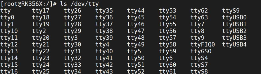
/dev/ttyX (X is a numeric number, such as 0, 1, 2, 3, etc.) device node: tty is the abbreviation for teletype. In Linux,
/dev/ttyXthey all represent local terminals. The 63 local terminals generated by the Linux kernel during initialization include/dev/tty1~/dev/tty63a total of 63 local terminals, which can be the LCD display, keyboard, mouse, etc. connected to the development board.Serial port terminal device node: From the development board schematic, we can see that the iTOP-3568 development board has four serial ports: UART2, UART4, UART7, and UART9. Among them, UART2 is the serial debugging terminal, and its corresponding device node is
/dev/ttyFIQ0, and the other three serial ports UART4, UART7, UART9 correspond to/dev/ttyS4、/dev/ttyS7、/dev/ttyS9。USB-based virtual serial port:
ttyGS0andttyUSBX(X is a numeric number, such as 0, 1, 2, 3, etc.) are all USB virtual serial ports. Among them, ttyGS0 is the virtual serial port created by the USB flashing interface. After the system starts, you can enter the development board console via the “adb shell” command in a Windows terminal. ttyUSBX here is the virtual serial port of the 4G module.
struct termios structure
struct termiosis a structure in the Linux kernel used to describe the parameters of terminal devices (including serial port devices).
It is defined in<linux/termios.h>header file. It contains multiple fields for configuring and managing the attributes and behavior of terminal devices, including input/output baud rate, data bits, parity bits, stop bits, etc. Its definition is as follows:
1234567 | struct termios { tcflag_t c_iflag; // Input mode flags tcflag_t c_oflag; // Output mode flags tcflag_t c_cflag; // Control mode flags tcflag_t c_lflag; // Local mode flags cc_t c_cc[NCCS]; // Control character array}; |
The following are some important fields of the struct termios structure:
tcflag_t c_iflag: This field contains input mode flags, used to configure the input behavior of the terminal device, such as input control characters, input data processing, etc.tcflag_t c_oflag: This field contains output mode flags, used to configure the output behavior of the terminal device, such as output data processing, output control characters, etc.tcflag_t c_cflag: This field contains control mode flags, used to configure the control parameters of the terminal device, such as baud rate, data bits, stop bits, parity bits, etc.tcflag_t c_lflag: This field contains local mode flags, used to configure the local operations and input/output behavior of the terminal device.cc_t c_cc[NCCS]: This field contains an array of special control characters, used to configure the control characters of the terminal device, such as the erase character, end character, stop character, etc.
Input mode
Input mode settings
| Member | Meaning of the corresponding member |
|---|---|
| IGNBRK | Ignore break condition on input |
| BRKINT | Send SIGINT signal when a break condition is detected on input |
| IGNPAR | Ignore framing errors and parity errors |
| PARMRK | Mark parity errors |
| INPCK | Perform parity checking on received data |
| ISTRIP | Strip all received data to 7 bits, i.e., remove the eighth bit |
| INLCR | Translate received NL (newline) to CR (carriage return) |
| IGNCR | Ignore received CR (carriage return) |
| ICRNL | Translate received CR (carriage return) to NL (newline) |
| IUCLC | Map received uppercase characters to lowercase |
| IXON | Enable output software flow control |
Output mode
Output mode controls the processing of output characters, i.e., how character data sent by the application is processed before being transmitted to the serial port or screen. It can be used toc_oflagThe macros for the members are as follows:
| Member | Meaning of the corresponding member |
|---|---|
| OPOST | Enable output processing; if this flag is not set, all other flags are ignored. |
| OLCUC | Convert uppercase characters in output to lowercase |
| ONLCR | Convert newline (NL ‘\n’) in output to carriage return (CR ‘\r’) |
| OCRNL | Convert carriage return (CR ‘\r’) in output to newline (NL ‘\n’) |
| ONOCR | Do not output carriage return (CR) at column 0 |
| ONLRET | Do not output carriage return |
| OFILL | Send fill characters to provide delay |
| OFDEL | If this flag is set, it indicates that the fill character is the DEL character; otherwise, it is the NULL character. |
Control mode
In this structure, the most importantc_cflag, which can control the hardware characteristics of the terminal device in control mode. For example, for a serial port, this field is relatively important; it can set hardware characteristics such as baud rate, data bits, parity bits, and stop bits. By settingstruct termiosin the structurec_cflagThe flags of the member configure the control mode. Can be usedc_cflagThe flags of the member are as follows:
Baud Rate bitmask
| Constant name | meaning |
|---|---|
| B0 | 0 baud rate (drop DTR) |
| B1800 | 1800 baud rate |
| B2400 | 2400 baud rate |
| B4800 | 4800 baud rate |
| B9600 | 9600 baud rate |
| B19200 | 19200 baud rate |
| B38400 | 38400 baud rate |
| B57600 | 57600 baud rate |
| B115200 | 115200 baud rate |
Data Bits bitmask
| Constant name | meaning |
|---|---|
| CS5 | 5 data bits |
| CS6 | 6 data bits |
| CS7 | 7 data bits |
| CS8 | 8 data bits |
Stop bits bitmask
| Constant name | meaning |
|---|---|
| CSTOPB | 2 stop bits (if not set, 1 stop bit) |
Other control flags
| Constant name | meaning |
|---|---|
| CREAD | Receive enable |
| PARENB | Parity enable |
| PARODD | Use odd parity instead of even parity |
| HUPCL | Hang up on last close (drop DTR) |
| CLOCAL | Local connection (does not change port owner) |
| LOBLK | Block job control output |
| CRTSCTS | Hardware flow control enable |
Local mode
Local mode is used to control the terminal’s local data processing and working mode. By settingstruct termiosIn the structure,c_lflagthe member flags configure the local mode. Can be used forc_lflagThe flags of the member are as follows:
| Constant name | Meaning description |
|---|---|
| INPCK | Enable parity checking. When enabled, the system checks received data for parity errors. |
| IGNPAR | Ignore parity errors. Even if a parity error is detected, data is not discarded and no exception is generated. |
| PARMRK | When a parity error occurs, mark the character (usually by inserting\033and\000). Used for debugging. |
| ISTRIP | Clear the 8th bit (most significant bit) of all received data bytes, i.e., keep only the lower 7 bits (for 7-bit character sets). |
| IXON | EnableOutput software flow control(XON/XOFF). When the buffer is full, send XOFF (^S) to pause transmission; when idle, send XON (^Q) to resume. |
| IXOFF | EnableInput software flow control. Allows the device to actively send XON/XOFF control characters at the receiving end to control the sender. |
| IXANY | Allow any character (not just XON) to trigger flow control restart. By default, only XON can restart transmission. |
| IGNBRK | Ignore break condition. That is, ignore line break signals (such as prolonged low level). |
| BRKINT | When a break is detected, send aSIGINTsignal to the process (usually used to interrupt program execution). |
| INLCR | Convert newline characters (NL,\n) to carriage return (CR,\r). Common on some older terminals. |
| IGNCR | Ignore carriage return characters (CR,\r), do nothing. |
| ICRNL | Convert carriage return characters (CR,\r) to newline characters (NL,\n). This is a common end-of-line handling method. |
| ICANON | Enable “Canonical Mode”. In this mode, input is processed line by line (terminated by newline), supporting editing (such as backspace, delete), echo, etc. When disabled, it enters “Raw Mode”. |
Special control characters
Special control characters are character combinations such as Ctrl+C, Ctrl+Z, etc. When the user types such a key combination, the terminal takes special action.struct termiosIn the structure,c_ccThe array maps various special characters to corresponding support functions. Each character position (array index) is defined by the corresponding macro, as shown below.
| Constant name | Function | Default key | Use case |
|---|---|---|---|
| VKILL | Delete entire line | Ctrl+U | Edit long command |
| VEOF | End of file | Ctrl+D | Submit input or close |
| VEOL | End-of-line marker | CR | Compatible with old terminals |
| VEOL2 | Second end-of-line | LF | Multiple newline formats |
| VMIN | Minimum number of characters | - | Non-canonical mode read control |
| VTIME | Timeout | - | Non-canonical mode read control |
| VINTR | interrupt | Ctrl+C | Terminate program |
| VQUIT | Exit | Ctrl+\ | Terminate process and dump |
| VERASE | Delete character | Backspace | Single-character editing |
Common serial port control functions
tcgetattr()
Function: Get the attribute configuration of the current terminal (or serial port device).
Prototype:
12 | int tcgetattr(int fd, struct termios *termios_p); |
- Parameters:
fd: File descriptor (e.g., an open serial port/dev/ttyS0)termios_p: points tostruct termiospointer to store the current configuration
- Return value: returns 0 on success, -1 on failure
- Purpose: Reads the current serial port’s baud rate, data bits, parity, flow control, input/output modes, and other settings.
Usually, call this function before modifying the serial port to save the original configuration, so that it can be restored when the program exits.
tcsetattr()
Function: Set the attribute configuration of the terminal (or serial port).
Prototype:
1 | int tcsetattr(int fd, int optional_actions, const struct termios *termios_p); |
- Parameters:
fd: file descriptoroptional_actions: specifies when to apply the new settings, common values:TCSANOW: takes effect immediatelyTCSADRAIN: takes effect after output completes (commonly used for output-related settings)TCSAFLUSH: takes effect immediately after flushing input/output buffers
termios_p: containing the new configurationstruct termiospointer
- Return value: returns 0 on success, -1 on failure
- Purpose: applies new serial port parameters (e.g., baud rate, 8N1 configuration, raw mode, etc.)
⚠️ After modification, it is recommended to check the return value to ensure the settings are applied successfully.
cfgetispeed() and cfgetospeed()
Function: get the input (receive) and output (transmit) baud rates, respectively.
Prototype:
12 | speed_t cfgetispeed(const struct termios *termios_p);speed_t cfgetospeed(const struct termios *termios_p); |
- Return value: baud rate constant (e.g.,
B9600,B115200), not the actual numeric value (e.g., 9600) - Note: returns a
speed_tof typeMask value, cannot be used directly as an integer
The actual baud rate must be converted via a lookup table or system-specific method (the POSIX standard does not define a conversion function from
speed_tto an integer; some systems provide extension interfaces).
cfsetispeed() and cfsetospeed()
Function: set the input and output baud rates, respectively.
Prototype:
12 | int cfsetispeed(struct termios *termios_p, speed_t speed);int cfsetospeed(struct termios *termios_p, speed_t speed); |
Parameters:
termios_p: points to the object to be modifiedtermiosStructurespeed: baud rate constant (e.g.,B9600,B115200)
Return value: returns 0 on success, -1 on failure
Typical usage:
12345
struct termios tty;tcgetattr(fd, &tty);cfsetospeed(&tty, B115200);cfsetispeed(&tty, B115200);tcsetattr(fd, TCSANOW, &tty);
Usually the transmit and receive baud rates are set to the same value (full-duplex communication), unless there are special requirements.
tcflush() and tcflow()
tcflush()
Function: Clear the terminal’s input or output queue.
Prototype:
1 | int tcflush(int fd, int queue_selector); |
queue_selectorValues:TCIFLUSH: Clearinput queue(data received but not yet read)TCOFLUSH: Clearoutput queue(data to be sent but not yet transmitted)TCIOFLUSH: Clear both input and output queues simultaneously
- Purpose: Clear dirty data before reconfiguring the serial port or restarting communication.
tcflow()
Function: Control the serial port’s data flow (pause/resume transmission).
Prototype:
1 | int tcflow(int fd, int action); |
actionValues:TCOOFF: Pauseoutput(the sender stops sending)TCOON: ResumeoutputTCIOFF: PauseInput(send XOFF to the peer, requesting it to pause)TCION: ResumeInput(Send XON to the peer, allowing it to continue sending)
- Purpose: manually implement software flow control (XON/XOFF), or handle buffer overflow.
💡 Note:
tcflow()DependsIXON/IXOFFon whether the flag is enabled.
Serial port operation flow
Set the baud rate of the serial port
When writing serial port applications, setting the serial port baud rate is one of the necessary steps; it determines the data transmission rate.
In Linux, the cfsetspeed() function is usually used to set the baud rate. The required header file and function prototype for cfsetspeed() are as follows:
123 | int cfsetspeed(struct termios *termios_p, speed_t speed); |
It accepts a pointer tostruct termiosa structure and a baud rate constant as input parameters; returns 0 on success, -1 on failure.
This function actually setsc_cflagthe baud rate in the field (setting both input and output baud rates). For example, to set the baud rate to 115200, you can call the following code:
1234567 | struct termios options;// Get the current terminal configurationtcgetattr(fd, &options);// Set the baud rate to 115200cfsetspeed(&options, B115200);// Write the new terminal configuration to the terminaltcsetattr(fd, TCSANOW, &options); |
Note the following:
- You need to first open the serial port device file and obtain the current attributes of the serial port (including other attributes such as baud rate). You can use
tcgetattr()the function to get the attribute values and store them in atermiosstructure variable. - When setting the baud rate, you need to call
cfsetspeed()the function and pass a baud rate constant as a parameter. Commonly used baud rate constants includeB9600、B115200etc. These constants can be found in the header filetermios.h. - After the setup is complete, it is necessary to use
tcsetattr()function to write the new attribute values back to the serial port device.
Set data bit size
In serial communication, the data bits refer to the number of data bits actually contained in each character (byte). Typically, a character contains 8 bits (i.e., 8 0s or 1s), but sometimes it can be 7 bits or other values.
When writing serial port application programs, it is necessary to usestruct termiosin the structurec_cflagmember variable to set the data bit size. Specifically, it is necessary toc_cflagclear the bits related to the data bits in the member variable, and then set the corresponding values as needed.
The clearing operation usually uses the bitwise AND (&) operator and the bitwise NOT (~) operator. The specific steps are as follows:
1 | new_cfg.c_cflag &= ~CSIZE; // Clear the bits related to the data bits |
Here, CSIZE is a macro definition that represents the bit mask for the data bits. The macro definition is usually defined intermios.hthe header file, and its values are as follows:
1 | |
Through the clearing operation, all bits related to the data bits are set to 0. Next, you can use the bitwise OR (|) operator and macro definitions to set the specific number of data bits, for example:
1 | new_cfg.c_cflag |= CS8; // Set the number of data bits to 8 |
At this point, the CS8 macro definition will be interpreted as an 8-bit bit mask, and through the bitwise OR operation, it is set intoc_cflagthe member variable, thereby completing the data bit setting.
Set parity bit
The parity bit configuration of the serial port involves a total ofstruct termiostwo member variables in the structure:c_cflagandc_iflag。
First, forc_cflagmember, it is necessary to addPARENBflag to enable the parity check function of the serial port. Only after enabling the parity check function will a parity bit be generated for the output data, thereby performing parity checks on the input data.
At the same time, forc_iflagmember, it is also necessary to addINPCKflag, so that parity checking can be performed on the received data, as shown in the following code:
Odd parity enable
12 | new_cfg.c_cflag |= (PARODD | PARENB); // Set to odd paritynew_cfg.c_iflag |= INPCK; // Enable parity check |
Even parity enable
123 | new_cfg.c_cflag &= ~PARODD; // Set to even paritynew_cfg.c_cflag |= PARENB; // Enable parity checknew_cfg.c_iflag |= INPCK; // Perform parity check on input data |
No parity
12 | new_cfg.c_cflag &= ~PARENB; // Disable parity checknew_cfg.c_iflag &= ~INPCK; // Do not perform parity check |
Set stop bits
In serial communication, the stop bit is used to specify the end position of each data frame.
After transmitting a complete data byte, one or more stop bits are usually required so that the receiving end can determine the end of a data frame.
The number of stop bits is usually 1 or 2, with 1 stop bit being widely used, while 2 stop bits are less commonly used.
In Linux, bystruct termiossetting in the structurec_cflagthe member variable’sCSTOPBflag to control the number of stop bits. WhenCSTOPBit is 0, only 1 stop bit is used; whenCSTOPBit is 1, then 2 stop bits are used.
For example, the following code sets the stop bits of the serial port to 1 bit:
1 | new_cfg.c_cflag &= ~CSTOPB; // Set stop bits to 1 bit |
example
123456789101112131415161718192021222324252627282930313233343536373839404142434445464748495051525354555657585960616263646566676869707172737475767778798081828384858687888990919293949596979899100101102103104105106107108109110111112113114115116 | /* Function to set serial port parameters */int set_uart(int fd, int speed, int bits, char check, int stop) { struct termios newtio, oldtio; // Step 1: Save the original serial port configuration if(tcgetattr(fd, &oldtio) != 0) { printf("tcgetattr oldtio error\n"); return -1; } bzero(&newtio, sizeof(newtio)); // Step 2: Set the control mode flag newtio.c_cflag |= CLOCAL | CREAD; newtio.c_cflag &= ~CSIZE; // Step 3: Set data bits switch(bits) { case 7: newtio.c_cflag |= CS7; break; case 8: newtio.c_cflag |= CS8; break; } // Step 4: Set parity bit switch(check) { case 'O': // Odd parity newtio.c_cflag |= PARENB; newtio.c_cflag |= PARODD; newtio.c_iflag |= (INPCK | ISTRIP); break; case 'E': // Even parity newtio.c_cflag |= PARENB; newtio.c_cflag &= ~PARODD; newtio.c_iflag |= (INPCK | ISTRIP); break; case 'N': // No parity newtio.c_cflag &= ~PARENB; break; } // Step 5: Set baud rate switch(speed) { case 9600: cfsetispeed(&newtio, B9600); cfsetospeed(&newtio, B9600); break; case 115200: cfsetispeed(&newtio, B115200); cfsetospeed(&newtio, B115200); break; } // Step 6: Set stop bits switch(stop) { case 1: newtio.c_cflag &= ~CSTOPB; // 1 stop bit break; case 2: newtio.c_cflag |= CSTOPB; // 2 stop bits break; } // Step 7: Flush input queue tcflush(fd, TCIFLUSH); // Step 8: Apply configuration immediately if (tcsetattr(fd, TCSANOW, &newtio) != 0) { printf("tcsetattr newtio error\n"); return -2; } return 0;}int main(int argc, char *argv[]) { int fd; char buf[128]; int count; // Step 9: Open the serial port device fd = open("/dev/ttyS9", O_RDWR | O_NOCTTY | O_NDELAY); if (fd < 0) { printf("open error \n"); return -1; } // Set serial port parameters set_uart(fd, 115200, 8, 'N', 1); // Write data write(fd, argv[1], strlen(argv[1])); sleep(1); // Read data count = read(fd, buf, sizeof(buf)); buf[count] = '\0'; // Output the read data printf("read message is %s\n", buf); // Close the serial port device close(fd); return 0;} |
GPS module programming
The Global Navigation Satellite System (GNSS) is a system that uses satellite technology to provide precise time and location information to users worldwide.
The positioning module is usually connected to the CPU via a serial port, and then the CPU uploads the coordinates through other methods such as Wi-Fi and Bluetooth.
The GPS module schematic is as follows
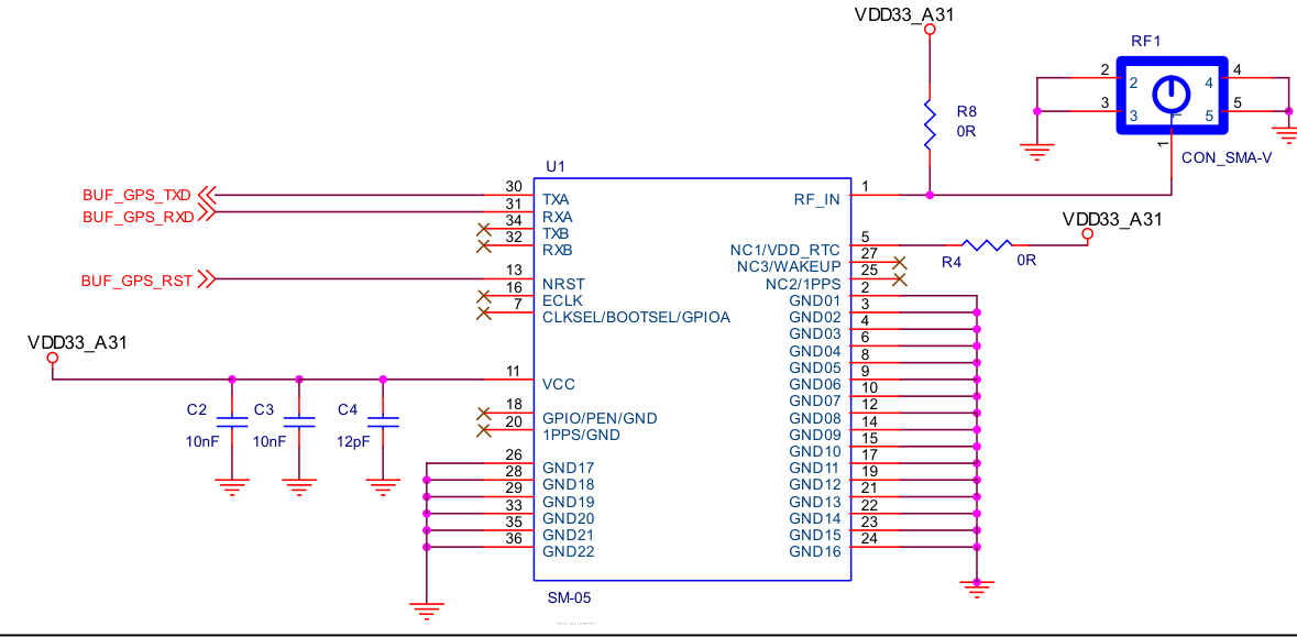
whereBUF_GPS_RSTThe interface is left floating and not connected. The following is the connection table for the 20-pin base connected to the RK3568 development board GPIO interface:
| GPS module pin numbers | GPS module pin name | Development board pin number connected to | Development board pin name connected to |
|---|---|---|---|
| 2 | BUF_GPS_TXD | 8 | UART9_RX_M1 |
| 3 | BUF_GPS_RXD | 6 | UART9_TX_M1 |
| 11 | GND | 19/20 | GND |
| 19 | VDD33_A31 | 2/4 | VCC3V3_SYS |
After the GPS module is connected, the antenna should be placed outdoors.
GPS data frame introduction
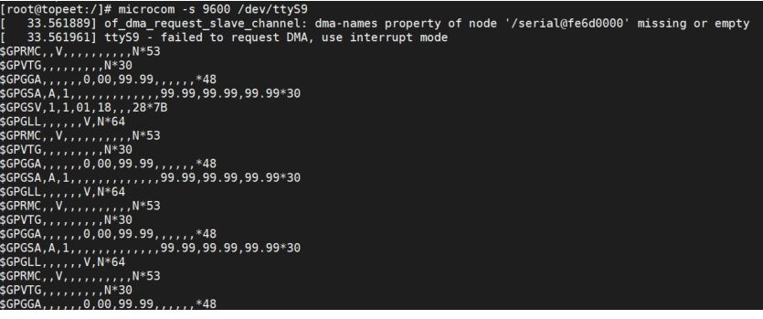
Listed here are common data types in the NMEA format, including:
- GPRMC (Recommended Minimum Specific GPS/Transit data): GPRMC data type provides the most basic GPS positioning information such as position, speed, and heading. This data type is commonly used in navigation systems and ship autopilot systems.
- GPVTG (Track Made Good and Ground Speed): GPVTG data type provides ground course angle and ground speed information, used to display navigation information for moving objects such as ships and vehicles.
- GPGGA (Global Positioning System Fix Data): GPGGA data type includes position information such as positioning solution, time, position accuracy, and altitude, and is usually used by receivers to display the current position in real time.
- GPGSA (GPS DOP and Active Satellites): GPGSA data type includes DOP value and current satellite positioning status. It is used to provide information such as the number of available satellites and the calculated position geometric dilution of precision (DOP).
- GPGSV (GPS Satellites in View): GPGSV data type provides information on currently visible satellites, including satellite PRN, elevation, azimuth, signal strength, and other information. This information helps the receiver find more satellites and improve positioning accuracy.
- GPGLL (Geographic Position - Latitude/Longitude): GPGLL data type provides latitude and longitude information, used to describe the receiver’s current latitude and longitude position.
We only need to pay attention to the GPRMC message, as shown in the figure below:

GPRMC (Recommended Minimum Specific GNSS Data) is a common GNSS data frame format used to transmit position information between GNSS devices or between GNSS devices and other devices. The following is the information contained in the GPRMC data frame:
| Field number | Field value (example) | meaning | Detailed explanation |
|---|---|---|---|
| 0 | $GPRMC | Message ID | Indicates that this is the ‘Recommended Minimum Positioning Information’ frame.GPIndicates that it is provided by the GPS system; other systems such as GLONASS useGL, BeiDou usesBDorGB. In this example, the$GPRMCindicates that this frame comes from the GPS system. |
| 1 | 083634.00 | UTC time | Format:hhmmss.sssrepresents 08:36:34.000 UTC → Beijing Time = UTC + 8 hours → 16:36:34 (4:36 PM) |
| 2 | A | Status indicator | -A:Valid position fix(Active / Valid) -V:Invalid position fix(Void / Invalid), possibly due to weak signal or no satellite lock |
| 3 | 3854.62194 | Latitude (value) | Format:ddmm.mmmmthat is, 38°54.62194′ Convert to decimal degrees:38 + 54.62194/60 ≈ 38.910366° N |
| 4 | N | Latitude hemisphere | -N: North (N) -S: South (S) |
| 5 | 11526.10876 | Longitude (value) | Format:dddmm.mmmmthat is, 115°26.10876′ Convert to decimal degrees:115 + 26.10876/60 ≈ 115.435146° E |
| 6 | E | Longitude hemisphere | -E: East (E) -W: West (W) |
| 7 | 0.932 | Ground speed (knots) | Unit:knots. 1 knot = 1 nautical mile/hour ≈ 1.852 km/h →0.932 × 1.852 ≈ 1.73 km/h(walking speed) |
| 8 | 55.00 | Ground heading | Unit:Degree (°), toTrue north is 0°, range: 0.0 ~ 359.9°. 55° indicates northeast direction. |
| 9 | 200624 | UTC date | Format:ddmmyy→ June 20, 2024。 |
| 10 | (Empty) | magnetic declination | Optional field, indicating the angle between magnetic north and true north (unit: degrees). |
| 11 | (Empty) | magnetic declination direction | EorW, used with field 10 |
| 12 | (Empty) | Positioning Mode | -A: Autonomous Positioning (Autonomous) -D: Differential positioning (DGPS) -E: Estimation (Dead Reckoning) -N: No positioning (Note: some modules output in this field, some are placed in$GPGSAMiddle) |
| 13 | D*50 | checksum | From$after the first character to*do all preceding characters XOR checksum, used to verify data integrity.*50is the hexadecimal value of the checksum. |
example
gps.h
1234567891011121314151617181920212223242526 | // Define the structure gprmc_data, used to store parsed GPS datastruct gprmc_data { char id; // Data identifier (unused) int time; // UTC time (hhmmss.sss format) char state; // Status indicator (A=valid, V=invalid) float latitude; // Latitude (ddmm.mmmm format) char NS; // Latitude hemisphere (N=North, S=South) float longitude; // Longitude (dddmm.mmmm format) char EW; // Longitude hemisphere (E=East, W=West) float speed; // Ground speed (knots) int date; // UTC date (ddmmyy format) char mode; // Mode indicator (A=autonomous positioning, D=differential positioning) char check; // Checksum (unused)};// Declare function prototype: set serial port parametersextern int set_uart(int fd, int speed, int bits, char check, int stop);// Declare function prototype: parse GPS dataextern void get_gps_data(char *buff, struct gprmc_data *gps_data); |
gps.c
12345678910111213141516171819202122232425262728293031323334353637383940 | // Function: get_gps_data// Description: Parse GPS data from the data buffer and fill it into the structure// Parameters:// - buff: pointer to the buffer containing GPS data// - gps_data: pointer to the structure gprmc_pointer to data, used to store parsed GPS data// Return value: nonevoid get_gps_data(char *buff, struct gprmc_data *gps_data) { char *p=NULL; // Find the position in the buffer that starts with "$GPRMC" p = strstr(buff, "$GPRMC"); if (p == NULL) { // printf("Error: $GPRMC not found in buffer.\n"); return; // If "$GPRMC" is not found, return directly } // Use the sscanf function to parse data from string p according to the specified format, and store it into the corresponding member variables in the gps_data structure sscanf(p, "$GPRMC,%d.00,%c,%f,%c,%f,%c,%f,,%d,,,%c,%*c",\ &(gps_data->time),\ &(gps_data->state),\ &(gps_data->latitude),\ &(gps_data->NS),\ &(gps_data->longitude),\ &(gps_data->EW),\ &(gps_data->speed),\ &(gps_data->date),\ &(gps_data->mode)); // Print some parsed GPS data to verify the parsing is correct (optional) printf("state:%c, %c:%f, %c:%f\n", gps_data->state, gps_data->NS, gps_data->latitude, gps_data->EW, gps_data->longitude);} |
uart.c
12345678910111213141516171819202122232425262728293031323334353637383940414243444546474849505152535455565758596061626364656667686970717273747576777879808182 | /* Function to set serial port parameters */int set_uart(int fd, int speed, int bits, char check, int stop) { struct termios newtio, oldtio; // Step 1: Save the original serial port configuration if(tcgetattr(fd, &oldtio) != 0) { printf("tcgetattr oldtio error\n"); return -1; } bzero(&newtio, sizeof(newtio)); // Step 2: Set the control mode flag newtio.c_cflag |= CLOCAL | CREAD; newtio.c_cflag &= ~CSIZE; // Step 3: Set data bits switch(bits) { case 7: newtio.c_cflag |= CS7; break; case 8: newtio.c_cflag |= CS8; break; } // Step 4: Set parity bit switch(check) { case 'O': // Odd parity newtio.c_cflag |= PARENB; newtio.c_cflag |= PARODD; newtio.c_iflag |= (INPCK | ISTRIP); break; case 'E': // Even parity newtio.c_cflag |= PARENB; newtio.c_cflag &= ~PARODD; newtio.c_iflag |= (INPCK | ISTRIP); break; case 'N': // No parity newtio.c_cflag &= ~PARENB; break; } // Step 5: Set baud rate switch(speed) { case 9600: cfsetispeed(&newtio, B9600); cfsetospeed(&newtio, B9600); break; case 115200: cfsetispeed(&newtio, B115200); cfsetospeed(&newtio, B115200); break; } // Step 6: Set stop bits switch(stop) { case 1: newtio.c_cflag &= ~CSTOPB; // 1 stop bit break; case 2: newtio.c_cflag |= CSTOPB; // 2 stop bits break; } // Step 7: Flush input queue tcflush(fd, TCIFLUSH); // Step 8: Apply configuration immediately if (tcsetattr(fd, TCSANOW, &newtio) != 0) { printf("tcsetattr newtio error\n"); return -2; } return 0;} |