
Timeline
Timeline
2025-12-28
init
This article introduces the basic principles and implementation of the I2C bus protocol under Linux. The article first explains that I2C was invented by Philips, adopts a master-slave architecture, and performs synchronous serial communication through the SCL clock line and SDA data line. When idle, the bus is pulled high by pull-up resistors. It then summarizes the characteristics of I2C, including bus topology, physical layer interface, communication protocol, clock frequency (standard, fast, and high-speed modes), 7-bit addressing mechanism, and multi-master arbitration mechanism. The article also introduces that the RK3568 processor supports 6 hardware I2C interfaces, programmable clock frequency, and supports 7-bit and 10-bit address modes. In addition, it compares the advantages and disadvantages of hardware I2C and software I2C: hardware I2C has low CPU usage, high speed, and stability, but high cost and fixed interfaces; software I2C simulates timing through GPIO, is flexible and low-cost, but has high CPU usage and lower speed. Finally, it explains the role of I2C pull-up resistors, which is to ensure that the bus remains at a high level when idle, avoiding high-impedance state being disturbed by noise.
Linux Driver Notes
| Table of Contents | Links |
|---|---|
| 1. Linux Driver Framework | |
| 2. Linux Driver Loading Logic | |
| 3. Character Device Basics | |
| 4. Concurrency and Race Conditions | |
| 5. Advanced Character Device Topics | |
| 6. Interrupts | |
| 7. Platform Bus | |
| 8. Device Tree | |
| 9. Device Model | |
| 10. Hotplug | |
| 11. pinctrl Subsystem | |
| 12. GPIO subsystem | |
| 13. Input subsystem | |
| 14. 1-Wire | |
| 15. I2C | |
| 16. SPI | |
| 17. UART | |
| 18. PWM | |
| 19. RTC | |
| 20. Watchdog | |
| 21. CAN | |
| 22. Network devices | |
| 23. ADC | |
| 24. IIO | |
| 25. USB | |
| 26. LCD |

Introduction to I2C
The famous Dutch electronics company Philips invented a communication protocol for interconnecting integrated circuits, called I2C (Inter-Integrated Circuit).

BeforeIn the idle state,**SDA and SCL are generally pulled high by pull-up resistors, maintaining a high level state.**When data transmission is needed, the high and low levels of SCL and SDA generate the signals required by the I2C bus for data transfer.
Features
- Bus topology
The I2C bus uses a master-slave architecture, consisting of one master device and one or more slave devices. The master device is responsible for initiating data transmission, and the slave devices respond to the master’s requests.
- Physical layer interface
The I2C bus uses two lines for communication:SCL(Serial Clock Line) Clock line: the master device provides the clock signal.
SDA(Serial Data Line) Data line: used for bidirectional data transmission.
These two lines usually require pull-up resistors to maintain the high level state of the signal.
- Communication protocol
I2C usessynchronous serial communicationIn this mode, the master initiates communication and provides the clock. The master first sends a START signal, then sends the slave address and data transfer direction (read or write). After receiving its own address, the slave sends an acknowledgment signal indicating it is ready to receive or send data. Then the master and slave can begin data transfer. When communication ends, the master sends a STOP signal.
Clock frequency
The I2C bus supports multiple communication rates, common ones include:Standard mode: 100kbps
Fast mode: 400kbps
High-speed mode: 3.4Mbps
Addressing mechanism
I2C uses a 7-bit address space, capable of addressing up to 128 slave addresses (some of which are reserved, leaving about 112 actually usable). The first 7 bits of the address byte specify the slave device, and the last 1 bit indicates the read/write direction.
Each I2C peripheral corresponds to a unique address (this address can be obtained from the I2C peripheral device’s datasheet). Communication between the master and slave uses this address to determine which slave the master wants to communicate with.Multi-master support
The I2C bus supports multiple master devices sharing the same bus,avoiding conflicts through an arbitration mechanism. When multiple master devices attempt to occupy the bus simultaneously,the master that first detects a bus level inconsistent with its own transmitted level will withdraw from the competition, thereby ensuring that only one master gains control of the bus.Other features:
- The maximum bus capacitance is limited to 400pF。
- Data is transmitted in bytes。
- There are two implementation methods: hardware I2C and software I2C.
I2C on RK3568

- Supports 6 I2C interfaces, namely I2C0, I2C1, I2C2, I2C3, I2C4, I2C5
- Supports 7-bit and 10-bit address modes
- Software-programmable clock frequency
- The data transfer rate on the I2C bus can reach
- Standard mode up to 100Kbit/s
- Fast mode up to 400Kbit/s
- Fast Mode Plus up to 1Mbit/s
Hardware I2C and Software I2C
The 6 I2C interfaces here refer toHardware I2C,There is a dedicated hardware I2C circuit on the SoC, the introduction to hardware I2C is as follows
Hardware I2C
Hardware I2C,There is a dedicated hardware I2C circuit on the SoC
- Implementation method: The I2C bus protocol is implemented through a dedicated hardware I2C interface circuit.
- Advantages: Low CPU usage; the I2C bus is automatically handled by the hardware circuit. High transmission rate, up to 400kbit/s or 3.4Mbit/s. More reliable and stable, less susceptible to external interference.
- Disadvantages: Requires support from a dedicated hardware I2C interface circuit, with relatively high cost. The interface is fixed, not as flexible as software I2C.
- Scope of application: Suitable for high-speed, large-volume data transmission scenarios, such as connections to peripherals like LCD, EEPROM, etc.
Software I2C
refers tosimulating SCL and SDA signal lines via GPIO pins, when hardware I2C is insufficient, you can use GPIO to simulate software I2C. The introduction to software I2C is as follows:
- Implementation method: The I2C bus protocol is simulated through software, using general-purpose I/O pins to simulate the SCL and SDA signal lines.
- Advantages: Strong flexibility, can implement I2C interface on any I/O pin. Low cost, no additional hardware support required.
- Disadvantages: High CPU usage because the I2C timing needs to be simulated in software. The transmission rate is low, limited by CPU performance, generally around 100 kbit/s.
- Scope of application: Suitable for low-speed, small-data-volume transmission scenarios.
I2C pull-up resistors
In I2C, a pull-up resistor needs to be connected on both the SDA data line and the SCL clock line.
Function of connecting pull-up resistors
- Ensure the bus remains at a high level when idle.
The I2C bus uses open-drain/open-collector output. When no device is driving the bus, the bus is in a high-impedance state.. If no pull-up resistor is connected, the bus level will be uncertain and easily disturbed by noise. Connecting a pull-up resistor canensure the bus maintains a stable high level when idle.。
- Implement the wired-AND function.
The I2C bus allows multiple devices to be mounted on the same bus.。When one device pulls the bus low, the outputs of other devices are also pulled low. This is the wired-AND function, enabling bus arbitration.. If no pull-up resistor is connected, the level is uncertain when the bus is idle, and when one device pulls the bus low, other devices cannot sense the bus level change, making the wired-AND function impossible.
The pull-up resistor here cannot be chosen arbitrarily; it is necessary to considerthe bus capacitanceinfluence. The I2C bus has various parasitic capacitances, which can be equivalent to an RC charging circuit, as shown in the figure below.

When the bus transitions from low to high level, it needs to be powered through the pull-up resistor, charging the bus capacitance.
If the pull-up resistor value is too large, the charging time is too long, causing the rising edge to be too slow, which may affect communication;
If the pull-up resistor value is too small, the sink current is too large, and the device may not be able to pull the bus to a valid low level.
Therefore, in the I2C specification, the bus capacitance is required not to exceed 400pF. It is usually recommended to choose between 1k and 10k ohms, which can both ensure the rising edge speed and reliably pull the bus level low.
I2C pull-up resistor value calculation
Minimum value
Formula:
- is usually a common supply voltage such as 5V or 3.3V. On the iTOP-RK3568 development board, it is 3.3V.
- Indicates the maximum output voltage of the device at low level. The specific values are shown in the table below. Since VDD is 3.3V, the maximum value of VOL is 0.4.

- The maximum sink current of the device at low level. The specific values are shown in the table below. Through the value is 0.4, we can obtain the value in standard mode and fast mode is 3mA.

Calculate:
- Determine 、 and the value of: In RK3568,, take , the corresponding 。
- Substitute into the formula: Calculate the minimum value of the pull-up resistor: Usually a standard resistor value can be taken 910 Ω or 1 kΩ(If a value slightly lower than the theoretical minimum is allowed, the actual bus capacitance and speed requirements need to be considered.)
Maximum value
Formula:
- : the maximum value of the pull-up resistor (unit: Ω)
- : bus capacitance (unit: F), including the sum of PCB trace capacitance, pin capacitance, and device input capacitance
- : high-level rise time (unit: s). Generally, the rise time is from 0.3VDD to 0.7VDD. The specific value can be obtained from the datasheet.

From the figure above, we can obtain
- In standard mode the value is ≤ 1000ns.
- In fast mode the value is ≤ 300ns.
- In ultra-fast mode the value is ≤ 120ns
Calculate:
I2C operates in standard mode, the pull-up voltage is the pin capacitance is the connection capacitance is the high-level rise time . Calculate the maximum pull-up resistance.
- Calculate the bus capacitance:
- Substitute into the formula:
- Substitute the values to calculate:
Therefore, the maximum value of the pull-up resistor is approximately 29.5 kΩ。
Specific selection
Generally, the faster the I2C bus speed, the smaller the required pull-up resistor value. The specific selection is as follows:
100kbps: Generally choose a 10k pull-up resistor
400kbps: Generally choose a 4.7k pull-up resistor
1Mbps: Generally choose a 2.2k pull-up resistor
Of course, the above choices may not be correct and need to be adjusted according to actual test results. In practice, you can first select a pull-up resistor value based on experience for trial, without needing to dwell too much on the calculation formula.
I2C communication timing
Start signal and stop signal
All interactions areinitiated by the START (S) signal, and**terminated by the STOP (P) signal.**The specific communication timing diagrams for the start and stop signals are shown below:

- Start Signal (START): generated by the bus controller (i.e., the master), defined as a transition of the SDA line from high to low while the SCL line remains high。
- Stop Signal (STOP): generated by the bus controller, defined as a transition of the SDA line from low to high while the SCL line remains high。
After the START signal, the bus is considered busy until the STOP signal appears, after which the bus is considered free.
Data Format
- Each byte transmitted on the SDA line must be 8 bits long. Each transfer can contain any number of bytes.
- Each byte must be followed by an acknowledge bit.。
- Data is transmittedin the order of most significant bit (MSB) first.
- If the target device cannot immediately receive or send another complete byte of data due to operations such as handling internal interrupts, itcan put the controller into a waiting state by pulling the SCL line low. When the target device is ready to receive the next byte of data**, releasing the SCL line allows data transmission to continue**。
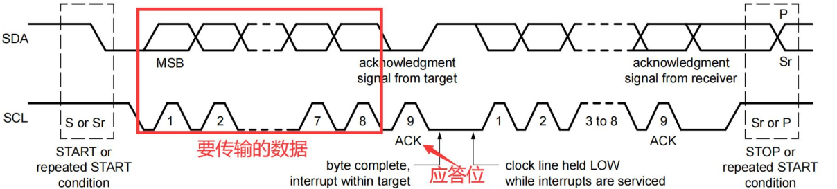
Acknowledge Signal and Non-acknowledge Signal
- The acknowledge signal occurs after each byte transfer. The acknowledge bit lets the receiving device indicate to the transmitting device that the byte data has been successfully received and the next byte can be sent.
- Acknowledge signal: WhenWhen the transmitting device releases the SDA line during the 9th clock pulse,, the receiving device can pull the SDA line low and keep it stable low during the high level of this clock.
- Non-acknowledge signal:The SDA line remains high during the 9th clock pulse., the controller can generate a stop signal to terminate the transmission, or a repeated start signal to begin a new transmission.

The five cases that cause a NACK signal include:
- No receiving device on the bus responds to the transmitted address.
- The receiving device is busy with other real-time functions and cannot start communication.
- The receiving device receives data or commands it cannot understand during the transmission.
- The receiving device cannot receive any more data bytes.
- The controller-receiver must indicate the end of transmission to the target transmitter.
Read/Write Direction
Data transfer format: first,send a 7-bit target address, followed by a read/write direction bit (R/W bit)。
The read/write direction bit is the 8th bit, 0 indicates a write operation (WRITE),1 indicates a read operation (READ)。
Data transmission is alwaysended by a stop signal (P) generated by the controller.. ButIf the controller needs to continue communicating on the bus, it can generate a repeated start condition (Sr) to address other target devices without first generating a stop condition.。
This allows various combinations of read/write formats to be implemented in the same transfer process.
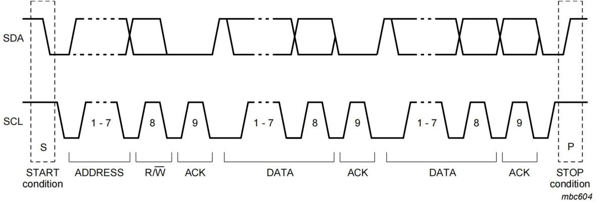
I2C waveform
Write operation

Before data transmission, the master must firstsend a start signal, the start signal is a transition of the SDA line from high to low level while the SCL line remains high, corresponding to the part shown in the figure, and the logic analyzer software also marks it with a green dot.
The write operation can be divided into the following steps:
- The master sends a start signal
- The master sends the I2C peripheral address and write operation, and waits for an acknowledge signal.
- The slave sends an acknowledgment signal.
- The master sends the register address and waits for an acknowledge signal.
- The slave sends an acknowledgment signal.
- The master sends the data to be written to the register and waits for an acknowledge signal.
- The slave sends an acknowledgment signal.
- The master sends a stop signal; if writing multiple registers, repeat steps 6 and 7.
Read operation
Whether it is a read operation or a write operation, the I2C peripheral address must be written first, so the initial waveform is the same.

The read operation can be divided into the following steps:
- The master sends a start signal
- The master sends the I2C peripheral address and write operation, and waits for an acknowledge signal.
- The slave sends an acknowledgment signal.
- The master sends the address of the register to be read and waits for an acknowledgment signal.
- The slave sends an acknowledgment signal.
- The master sends a start signal.
- The master sends the I2C peripheral address to read and a read operation, then waits for an acknowledgment signal.
- The slave sends an acknowledgment signal.
- The slave sends data, i.e., the data of the register to be read, and waits for an acknowledgment or non-acknowledgment signal.
- If the master is no longer reading data, it sends a non-acknowledgment signal; if it continues reading, it sends an acknowledgment signal.
I2C subsystem framework
Layered structure
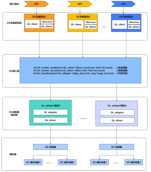
I2C device driver layer
The main function of the I2C device driver layer is to write drivers,to enable I2C peripherals to work properly., thencreates the corresponding device node., provides a standardized interface, so that upper-layer applications can conveniently interact with I2C devices.
Specifically, the I2C device driver layer includes the following key parts:
- i2c_client
- Represents a slave device connected to the I2C bus.
- Contains information such as the slave device’s address and the I2C adapter it belongs to.
/dev/i2XDevice node- Provides the device access interface for upper-layer applications.
- By opening/reading/writing/controlling the device node, applications can interact with I2C devices.
- The kernel I2C subsystem is responsible for forwarding application operations to the corresponding i2c_driver.
i2c_driver- Implements the driver for a specific I2C slave device.
- Responsible for device initialization, read/write, configuration, and other operations
- Interacts with the device through i2c_client
- Provides a standardized interface for upper layers to access the device
- I2C bus subsystem
- Manages the entire I2C bus, including registering/unregistering I2C adapters and slave devices
- Coordinate i2c_client and i2c_interaction between drivers
- Provides a unified I2C access interface for upper layers
I2C core layer
The I2C core layer is located between the I2C device driver layer and the I2C adapter driver layer, playing a connecting role, responsible for data transfer between the I2C device driver layer and the I2C adapter driver layer. The main functions of the I2C core layer are
i2c_master_sendi2c_master_recvi2c_transfer
i2c_master_sendandi2c_master_recvThese two functions are responsible forgenerating timing and data frames that conform to the I2C protocol, and performing actual bus operations through the corresponding I2C adapter driver.
where
i2c_master_sendandi2c_master_recvThe function is the basic read/write interface provided by the I2C core layer.
i2c_master_sendUsed to send data to I2C slave devices,i2c_master_recvUsed to receive data from slave devices.They respectively accept the following parameters:
struct i2c_client *client: pointer to the target I2C slave deviceconst char *buf/char *buf: data bufferint count: number of bytes to send/receive
Andi2c_transferThe function is a more comprehensive I2C transfer function,i2c_master_sendandi2c_master_recvThe function actually callsi2c_transfer
i2c_transfer function, which accepts the following parameters:
struct i2c_adapter *adap: Pointer to the target I2C adapterstruct i2c_msg *msgs: Pointer to an array of I2C messagesint num: Number of messages in the message array
Since the corresponding device node has already been created in the I2C device driver layer, with the driver it is possible to directly operate the specific I2C hardware. However, the I2C subsystem is not implemented this way; instead, an I2C core layer and an I2C adapter driver layer are added. Why is it designed this way?
The main reason is that through driver layering, it cansolve the problem of conflicts when multiple applications access the same I2C device at the same time, in addition, through thismodular design, it can improve code reusability and maintainability, allowing the I2C core layer and device drivers to be developed and upgraded independently, and I2C adapter drivers can also be optimized for different hardware platforms.
I2C adapter driver layer
The I2C adapter driver layer is another important component of the I2C subsystem, and it is responsible forimplementing the driver for the specific I2C hardware controller. The functions of the I2C adapter driver are as follows:
- Provide a standardized I2C transfer interface for the I2C core layer to call
- Implement timing control and data transmission/reception of the I2C bus protocol
- Manage slave devices on the I2C bus
- Handle I2C bus errors and abnormal conditions
I2C client code writing
struct i2c_client
12345678910111213141516171819202122232425262728293031323334353637383940414243 | /** * struct i2c_client - represent an I2C slave device * @flags: see I2C_CLIENT_* for possible flags * @addr: Address used on the I2C bus connected to the parent adapter. * @name: Indicates the type of the device, usually a chip name that's * generic enough to hide second-sourcing and compatible revisions. * @adapter: manages the bus segment hosting this I2C device * @dev: Driver model device node for the slave. * @init_irq: IRQ that was set at initialization * @irq: indicates the IRQ generated by this device (if any) * @detected: member of an i2c_driver.clients list or i2c-core's * userspace_devices list * @slave_cb: Callback when I2C slave mode of an adapter is used. The adapter * calls it to pass on slave events to the slave driver. * * An i2c_client identifies a single device (i.e. chip) connected to an * i2c bus. The behaviour exposed to Linux is defined by the driver * managing the device. */struct i2c_client { unsigned short flags; /* div., see below */ /* Must equal I2C_M_TEN below */ /* Must match I2C_M_STOP|IGNORE_NAK */ unsigned short addr; /* chip address - NOTE: 7bit */ /* addresses are stored in the */ /* _LOWER_ 7 bits */ char name[I2C_NAME_SIZE]; struct i2c_adapter *adapter; /* the adapter we sit on */ struct device dev; /* the device structure */ int init_irq; /* irq set at initialization */ int irq; /* irq issued by device */ struct list_head detected; i2c_slave_cb_t slave_cb; /* callback for slave mode */}; |
Device tree representation of I2C Client
Beforerk3568.dtsiIn the device tree, there are device tree nodes for I2C0, I2C1, I2C2, I2C3, I2C4, and I2C5. Here only the device tree node for I2C1 is listed, as follows:
123456789101112 | i2c1: i2c@fe5a0000 { compatible = "rockchip,rk3399-i2c"; reg = <0x0 0xfe5a0000 0x0 0x1000>; clocks = <&cru CLK_I2C1>, <&cru PCLK_I2C1>; clock-names = "i2c", "pclk"; interrupts = <GIC_SPI 47 IRQ_TYPE_LEVEL_HIGH>; pinctrl-names = "default"; pinctrl-0 = <&i2c1_xfer>; status = "disabled";}; |
i2c1: i2c@fe5a0000The node represents the I2C1 controller. If an I2C peripheral is attached to I2C1, you can directly add a child node for the I2C peripheral under the I2C1 controller node. The device tree node for FT5X06 is inkernel/arch/arm64/boot/dts/rockchip/topeet-screen-lcds.dtsin, as follows:
1234567891011121314151617 | &i2c1 { status = "okay"; ft5x061:ft5x06@38 { status = "disabled"; compatible = "edt,edt-ft5306"; reg = <0x38>; touch-gpio = <&gpio3 RK_PA5 IRQ_TYPE_EDGE_RISING>; interrupt-parent = <&gpio3>; interrupts = <RK_PA5 IRQ_TYPE_LEVEL_LOW>; reset-gpio = <&gpio0 RK_PB6 GPIO_ACTIVE_LOW>; touchscreen-size-x = <800>; touchscreen-size-y = <1280>; };}; |
This node appends the FT5X06 touch chip related node to the I2C1 controller node. That is,ft5x06 as a child node of i2c1
Disable the original rk3568 driver
- Uncheck the FT5X06 driver in menuconfig
- Before
topeet-screen-lcds.dtsSelect inLCD_TYPE_MIPI
1234567 | //#define LCD_TYPE_LVDS_10_1_1024X600 //in vp 2//#define LCD_TYPE_LVDS_10_1_1280X800_gt9271 //in vp 2//#define LCD_TYPE_LVDS_7_0 //in vp 2//#define LCD_TYPE_EDP_VGA //in vp 0//#define LCD_TYPE_HDMI_VP0 //hdmi in vp 0//#define LCD_TYPE_HDMI_VP1 //hdmi in vp 1 |
- The original ft5x06 device tree node status is changed from okay to disabled
12345678 | ...&ft5x061{ status = "okay";};... |
Writing the FT5X06 Client Device Tree
1234567 | &i2c1 { status = "okay"; myft5x06: my-ft5x06@38 { compatible = "my-ft5x06"; reg = <0x38>; };}; |
The description of the appended device tree node is as follows:
&i2c1: Indicates a reference to I2C controller 1.status = "okay";: Indicates enabling I2C controller 1.myft5x06: my-ft5x06@38: Defines a device node named myft5x06.my-ft5x06@38Indicates that the I2C address of this device is 0x38.compatible = "my-ft5x06";: This attribute is used to identify the type of device; here it indicates that this is a device namedmy-ft5x06device.reg = <0x38>;: This attribute defines the address of the device on the I2C bus, here it is 0x38
In addition to the I2C part, the FT5X06 touch chip also has two other GPIOs, namely the interrupt pin and the reset pin. The function matching table for each pin is as follows

Therefore we also need to describe them in the device tree
1234567891011121314151617 | &i2c1 { status = "okay"; ft5x061:ft5x06@38 { status = "okay"; compatible = "my-ft5x06"; reg = <0x38>; touch-gpio = <&gpio3 RK_PA5 IRQ_TYPE_EDGE_RISING>; interrupt-parent = <&gpio3>; interrupts = <RK_PA5 IRQ_TYPE_LEVEL_LOW>; reset-gpio = <&gpio0 RK_PB6 GPIO_ACTIVE_LOW>; pinctrl-names = "default"; pinctrl-0 = <&myft5x06_pins>; touchscreen-size-x = <800>; touchscreen-size-y = <1280>; };}; |
reset-gpio = <&gpio0 RK_PB6 GPIO_ACTIVE_LOW>;: Defines the reset pin of the device, connected toGPIO0the RK_PB6 pin, active low.interrupt-parent = <&gpio3>;: Specifies the parent node of the interrupt as GPIO3.touch-gpio = <&gpio3 RK_PA5 IRQ_TYPE_EDGE_RISING>;: Defines the touch pin of the device, connected to the RK_PA5 pin of GPIO3.interrupts = <RK_PA5 IRQ_TYPE_LEVEL_LOW>;: Further describes the interrupt trigger mode, which is low-level triggered.pinctrl-names = "default";andpinctrl-0 = <&myft5x06_pins>;: Specifies the default pin configuration used by the device.
The pinctrl node specified here is namedmyft5x06_pins, so it is also necessary to append to the pinctrl node. The appended content is as follows:
123456789 | &pinctrl { myft5x06 { myft5x06_pins: myft5x06-pins { rockchip,pins = <0 RK_PB6 RK_FUNC_GPIO &pcfg_pull_none>, <0 RK_PB6 RK_FUNC_GPIO &pcfg_pull_none>; } };} |
Writing an I2C Client in C
Generally, device tree is used to write I2C Client, but before the introduction of device tree, using C files is also acceptable.
struct i2c_adaper
12345678910111213141516171819202122232425262728293031323334 | /* * i2c_adapter is the structure used to identify a physical i2c bus along * with the access algorithms necessary to access it. */struct i2c_adapter { struct module *owner; unsigned int class; /* classes to allow probing for */ const struct i2c_algorithm *algo; /* the algorithm to access the bus */ void *algo_data; /* data fields that are valid for all devices */ const struct i2c_lock_operations *lock_ops; struct rt_mutex bus_lock; struct rt_mutex mux_lock; int timeout; /* in jiffies */ int retries; struct device dev; /* the adapter device */ unsigned long locked_flags; /* owned by the I2C core */ int nr; char name[48]; struct completion dev_released; struct mutex userspace_clients_lock; struct list_head userspace_clients; struct i2c_bus_recovery_info *bus_recovery_info; const struct i2c_adapter_quirks *quirks; struct irq_domain *host_notify_domain;}; |
i2c_get_adapter()
i2c_get_adapterThe main function is to, based on the given I2C adapter number nr, fromi2c_adapter_idrfind the correspondingi2c_adapterstructure, this function is defined indrivers/i2c/i2c-core-base.cfile, and the specific content is as follows
12345678910111213141516171819202122 | struct i2c_adapter *i2c_get_adapter(int nr){ struct i2c_adapter *adapter; // Get the i2c_adapter_lock in the idr mutex_lock(&core_lock); // In the i2c_adapter_find the adapter with the specified number in the idr adapter = idr_find(&i2c_adapter_idr, nr); if (!adapter) goto exit; // Try to acquire the reference count of the module to which the adapter belongs if (try_module_get(adapter->owner)) // Increment the reference count of the adapter device get_device(&adapter->dev); else adapter = NULL; exit: // Release the i2c_adapter_lock in the idr mutex_unlock(&core_lock); return adapter;}EXPORT_SYMBOL(i2c_get_adapter); |
i2c_put_adapter()
12345678910 | void i2c_put_adapter(struct i2c_adapter *adap){ if (!adap) return; module_put(adap->owner); /* Should be last, otherwise we risk use-after-free with 'adap' */ put_device(&adap->dev);}EXPORT_SYMBOL(i2c_put_adapter); |
When the driver is unloadedi2c_adapterthe structure needs to be freed, and when the structurei2c_put_adapterfunction is used to freei2c_adapterstructure,i2c_put_adapterThe function is also defined indrivers/i2c/i2c-core-base.cthe file
i2c_new_client_device()
i2c_new_client_deviceThe function is used to create and register the device corresponding to the I2C bus. After registration, the I2C subsystem automatically creates the corresponding device node for the device, allowing upper-layer applications to access and control it. This function is also defined indrivers/i2c/i2c-core-base.cthe file
12345678910111213141516171819202122232425262728293031323334353637383940414243444546474849505152535455565758596061626364656667686970717273747576777879808182838485868788899091 | /** * i2c_new_client_device - instantiate an i2c device * @adap: the adapter managing the device * @info: describes one I2C device; bus_num is ignored * Context: can sleep * * Create an i2c device. Binding is handled through driver model * probe()/remove() methods. A driver may be bound to this device when we * return from this function, or any later moment (e.g. maybe hotplugging will * load the driver module). This call is not appropriate for use by mainboard * initialization logic, which usually runs during an arch_initcall() long * before any i2c_adapter could exist. * * This returns the new i2c client, which may be saved for later use with * i2c_unregister_device(); or an ERR_PTR to describe the error. */struct i2c_client *i2c_new_client_device(struct i2c_adapter *adap, struct i2c_board_info const *info){ struct i2c_client *client; int status; // Allocate space for the i2c_client structure client = kzalloc(sizeof *client, GFP_KERNEL); if (!client) return ERR_PTR(-ENOMEM); // Set the adapter pointer of i2c_client client->adapter = adap; // from i2c_board_copy relevant information from the info structure to i2c_client client->dev.platform_data = info->platform_data; client->flags = info->flags; client->addr = info->addr; client->init_irq = info->irq; if (!client->init_irq) client->init_irq = i2c_dev_irq_from_resources(info->resources, info->num_resources); strlcpy(client->name, info->type, sizeof(client->name)); // Check whether the address is valid status = i2c_check_addr_validity(client->addr, client->flags); if (status) { dev_err(&adap->dev, "Invalid %d-bit I2C address 0x%02hx\n", client->flags & I2C_CLIENT_TEN ? 10 : 7, client->addr); goto out_err_silent; } /* Check for address business */ // Check whether the address is already occupied by another device status = i2c_check_addr_ex(adap, i2c_encode_flags_to_addr(client)); if (status) dev_err(&adap->dev, "%d i2c clients have been registered at 0x%02x", status, client->addr); // Set the device information of i2c_client client->dev.parent = &client->adapter->dev; client->dev.bus = &i2c_bus_type; client->dev.type = &i2c_client_type; client->dev.of_node = of_node_get(info->of_node); client->dev.fwnode = info->fwnode; i2c_dev_set_name(adap, client, info, status); // If there are device properties, add them to the device if (info->properties) { status = device_add_properties(&client->dev, info->properties); if (status) { dev_err(&adap->dev, "Failed to add properties to client %s: %d\n", client->name, status); goto out_err_put_of_node; } } // Register the device status = device_register(&client->dev); if (status) goto out_free_props; dev_dbg(&adap->dev, "client [%s] registered with bus id %s\n", client->name, dev_name(&client->dev)); return client;out_free_props: if (info->properties) device_remove_properties(&client->dev);out_err_put_of_node: of_node_put(info->of_node);out_err_silent: kfree(client); return ERR_PTR(status);}EXPORT_SYMBOL_GPL(i2c_new_client_device); |
i2c_bus_probe()
i2c_new_client_device()inclient->dev.busis assigned asi2c_bus_type, executei2c_driverwill be executed before the probe ofi2c_bus_probe(). Here, the client’s irq is assigned
123456789101112131415161718192021222324252627282930313233343536373839404142434445464748495051525354555657585960616263646566676869707172737475767778798081828384858687888990919293949596979899100101102103104105106107108109110111112113114115116117118119120121122123124125126127128129130131132133134 | struct bus_type i2c_bus_type = { .name = "i2c", .match = i2c_device_match, .probe = i2c_device_probe, .remove = i2c_device_remove, .shutdown = i2c_device_shutdown,};EXPORT_SYMBOL_GPL(i2c_bus_type);struct device_type i2c_client_type = { .groups = i2c_dev_groups, .uevent = i2c_device_uevent, .release = i2c_client_dev_release,};EXPORT_SYMBOL_GPL(i2c_client_type);static int i2c_device_probe(struct device *dev){ // Get the i2c_client structure from the device structure struct i2c_client *client = i2c_verify_client(dev); // Get the i2c_driver structure from the device structure struct i2c_driver *driver; int status; if (!client)// If the client does not exist, return 0 return 0; client->irq = client->init_irq; // If the client has no interrupt number, try to get the interrupt number if (!client->irq) { int irq = -ENOENT; // If the client uses Host Notify interrupt, use i2c_smbus_host_notify_to_irq to get the interrupt number if (client->flags & I2C_CLIENT_HOST_NOTIFY) { dev_dbg(dev, "Using Host Notify IRQ\n"); /* Keep adapter active when Host Notify is required */ pm_runtime_get_sync(&client->adapter->dev); irq = i2c_smbus_host_notify_to_irq(client); // If the device has a DT node, try to get the interrupt number from the DT node } else if (dev->of_node) { irq = of_irq_get_byname(dev->of_node, "irq"); if (irq == -EINVAL || irq == -ENODATA) irq = of_irq_get(dev->of_node, 0); // If the device has an ACPI association, try to get the interrupt number from ACPI } else if (ACPI_COMPANION(dev)) { irq = i2c_acpi_get_irq(client); } // If getting the interrupt number fails, set it to 0 if (irq == -EPROBE_DEFER) { status = irq; goto put_sync_adapter; } if (irq < 0) irq = 0; // Set the obtained interrupt number into the client structure client->irq = irq; } // Convert dev->driver to the i2c_driver type driver = to_i2c_driver(dev->driver); /* * An I2C ID table is not mandatory, if and only if, a suitable OF * or ACPI ID table is supplied for the probing device. */ // If the driver has no ID table, and the device also has no matching OF or ACPI ID table, return -ENODEV if (!driver->id_table && !acpi_driver_match_device(dev, dev->driver) && !i2c_of_match_device(dev->driver->of_match_table, client)) { status = -ENODEV; goto put_sync_adapter; } // If the client needs wake-up functionality, try to set up a wake-up interrupt if (client->flags & I2C_CLIENT_WAKE) { int wakeirq; wakeirq = of_irq_get_byname(dev->of_node, "wakeup"); if (wakeirq == -EPROBE_DEFER) { status = wakeirq; goto put_sync_adapter; } // Enable the device's wake-up function device_init_wakeup(&client->dev, true); // If a wake-up interrupt number is obtained and it is different from the normal interrupt number, set a dedicated wake-up interrupt if (wakeirq > 0 && wakeirq != client->irq) status = dev_pm_set_dedicated_wake_irq(dev, wakeirq); else if (client->irq > 0)// Otherwise, use the normal interrupt as the wake-up interrupt status = dev_pm_set_wake_irq(dev, client->irq); else status = 0; // If setting the wake-up interrupt fails, output a warning if (status) dev_warn(&client->dev, "failed to set up wakeup irq\n"); } dev_dbg(dev, "probe\n"); // Set the default clock value for the device status = of_clk_set_defaults(dev->of_node, false); if (status < 0) goto err_clear_wakeup_irq; // Attach the PM domain status = dev_pm_domain_attach(&client->dev, true); if (status) goto err_clear_wakeup_irq; /* * When there are no more users of probe(), * rename probe_new to probe. */ if (driver->probe_new)// Call the driver's probe_new or probe function status = driver->probe_new(client); else if (driver->probe) status = driver->probe(client, i2c_match_id(driver->id_table, client)); else status = -EINVAL; if (status)// If the probe function fails, clear the wake-up interrupt and detach the PM domain goto err_detach_pm_domain; return 0;err_detach_pm_domain: dev_pm_domain_detach(&client->dev, true);err_clear_wakeup_irq: dev_pm_clear_wake_irq(&client->dev); device_init_wakeup(&client->dev, false);put_sync_adapter: if (client->flags & I2C_CLIENT_HOST_NOTIFY) pm_runtime_put_sync(&client->adapter->dev); return status;} |
struct i2c_board_info
123456789101112131415161718192021222324252627282930313233343536373839 | // include/linux/i2c.h/** * struct i2c_board_info - template for device creation * @type: chip type, to initialize i2c_client.name * @flags: to initialize i2c_client.flags * @addr: stored in i2c_client.addr * @dev_name: Overrides the default <busnr>-<addr> dev_name if set * @platform_data: stored in i2c_client.dev.platform_data * @of_node: pointer to OpenFirmware device node * @fwnode: device node supplied by the platform firmware * @properties: additional device properties for the device * @resources: resources associated with the device * @num_resources: number of resources in the @resources array * @irq: stored in i2c_client.irq * * I2C doesn't actually support hardware probing, although controllers and * devices may be able to use I2C_SMBUS_QUICK to tell whether or not there's * a device at a given address. Drivers commonly need more information than * that, such as chip type, configuration, associated IRQ, and so on. * * i2c_board_info is used to build tables of information listing I2C devices * that are present. This information is used to grow the driver model tree. * For mainboards this is done statically using i2c_register_board_info(); * bus numbers identify adapters that aren't yet available. For add-on boards, * i2c_new_client_device() does this dynamically with the adapter already known. */struct i2c_board_info { char type[I2C_NAME_SIZE];// The type name of the I2C device, with a maximum length of I2C_NAME_SIZE unsigned short flags;// Flags of the I2C device, used to specify special attributes of the device unsigned short addr;// The address of the I2C device const char *dev_name;// The device name of the I2C device void *platform_data;// Platform data of the I2C device, can be NULL struct device_node *of_node;// The node pointer of the I2C device node in the device tree struct fwnode_handle *fwnode;// The fwnode handle of the I2C device node in ACPI const struct property_entry *properties;// Property list of the I2C device const struct resource *resources;// Resource list used by the I2C device unsigned int num_resources;// Number of resources used by the I2C device int irq;}; |
example
1234567891011121314151617181920212223242526272829303132333435363738394041 | // Define a pointer to the i2c_adapter structurestruct i2c_adapter *i2c_ada;// Define i2c_board_An array of info structures, used to describe the ft5x06 devicestatic struct i2c_board_info ft5x06[] = { { .type = "my-ft5x06", .addr = 0x38, }};static int __init i2c_client_test_init(void){ // Get the i2c adapter i2c_ada = i2c_get_adapter(1); if(!i2c_ada){ pr_err("Fail to get i2c_adapter1"); return -ENODEV; } // Register the ft5x06 device i2c_new_client_device(i2c_ada, ft5x06); return 0;}static void __exit i2c_client_test_exit(void){ // Release the i2c adapter i2c_put_adapter(i2c_ada);}module_init(i2c_client_test_init);module_exit(i2c_client_test_exit);MODULE_LICENSE("GPL");MODULE_AUTHOR("even629 <asqwgo@outlook.com>");MODULE_DESCRIPTION("This is a test sample for i2c client"); |
Core layer I2C communication
The main functions of the I2C core layer arei2c_master_send、i2c_master_recvandi2c_transfer, wherei2c_master_sendandi2c_master_recvThe functions are the basic read/write interfaces provided by the I2C core layer. These two functions are responsible for generating timing and data frames that conform to the I2C protocol, and perform actual bus operations through the corresponding I2C adapter driver. The two functions are defined ininclude/linux/i2c.hin the file
i2c_master_recv()
1234567891011121314 | // include/linux/i2c.h/** * i2c_master_recv - issue a single I2C message in master receive mode * @client: Handle to slave device * @buf: Where to store data read from slave * @count: How many bytes to read, must be less than 64k since msg.len is u16 * * Returns negative errno, or else the number of bytes read. */static inline int i2c_master_recv(const struct i2c_client *client, char *buf, int count){ return i2c_transfer_buffer_flags(client, buf, count, I2C_M_RD);}; |
i2c_master_send()
12345678910111213 | /** * i2c_master_send - issue a single I2C message in master transmit mode * @client: Handle to slave device * @buf: Data that will be written to the slave * @count: How many bytes to write, must be less than 64k since msg.len is u16 * * Returns negative errno, or else the number of bytes written. */static inline int i2c_master_send(const struct i2c_client *client, const char *buf, int count){ return i2c_transfer_buffer_flags(client, (char *)buf, count, 0);}; |
i2c_transfer_buffer_flags()
i2c_master_recv()andi2c_master_send()actually calledi2c_transfer_buffer_flags()this function
12345678910111213141516171819202122232425262728293031323334 | // drivers/i2c/i2c-core-base.c/** * i2c_transfer_buffer_flags - issue a single I2C message transferring data * to/from a buffer * @client: Handle to slave device * @buf: Where the data is stored * @count: How many bytes to transfer, must be less than 64k since msg.len is u16 * @flags: The flags to be used for the message, e.g. I2C_M_RD for reads * * Returns negative errno, or else the number of bytes transferred. */int i2c_transfer_buffer_flags(const struct i2c_client *client, char *buf, int count, u16 flags){ int ret; // Construct an i2c_msg structure to describe this transfer operation. struct i2c_msg msg = { .addr = client->addr, // Set slave device address .flags = flags | (client->flags & I2C_M_TEN),// Set transfer flags, including user-provided flags and the client object's own flags. .len = count,// Set the transfer data length. .buf = buf,// Set the data buffer. }; // Call the i2c_transfer function to perform data transfer. // This function returns the number of messages actually transferred successfully based on the number of messages to be transferred. ret = i2c_transfer(client->adapter, &msg, 1); /* * If everything went ok (i.e. 1 msg transferred), return #bytes * transferred, else error code. */ return (ret == 1) ? count : ret;}EXPORT_SYMBOL(i2c_transfer_buffer_flags); |
This function is used to transfer data over the I2C bus. It first constructs ai2c_msgstructure, describing this transfer operation, including the slave device address, transfer flags, data length, and data buffer. Then it callsi2c_transferfunction to perform the actual data transfer.
i2c_transfer()
1234567891011121314151617181920212223242526272829303132333435363738394041424344454647 | /** * i2c_transfer - execute a single or combined I2C message * @adap: Handle to I2C bus * @msgs: One or more messages to execute before STOP is issued to * terminate the operation; each message begins with a START. * @num: Number of messages to be executed. * * Returns negative errno, else the number of messages executed. * * Note that there is no requirement that each message be sent to * the same slave address, although that is the most common model. */int i2c_transfer(struct i2c_adapter *adap, struct i2c_msg *msgs, int num){ int ret; if (!adap->algo->master_xfer) {// If the adapter does not support the master_xfer operation, return an error directly. dev_dbg(&adap->dev, "I2C level transfers not supported\n"); return -EOPNOTSUPP; } /* REVISIT the fault reporting model here is weak: * * - When we get an error after receiving N bytes from a slave, * there is no way to report "N". * * - When we get a NAK after transmitting N bytes to a slave, * there is no way to report "N" ... or to let the master * continue executing the rest of this combined message, if * that's the appropriate response. * * - When for example "num" is two and we successfully complete * the first message but get an error part way through the * second, it's unclear whether that should be reported as * one (discarding status on the second message) or errno * (discarding status on the first one). */ ret = __i2c_lock_bus_helper(adap); if (ret) return ret; // Call__i2c_transfer to perform the actual message transfer. ret = __i2c_transfer(adap, msgs, num); i2c_unlock_bus(adap, I2C_LOCK_SEGMENT);// Unlock the I2C bus. return ret;}EXPORT_SYMBOL(i2c_transfer); |
struct i2c_adapter *adap: Indicates the I2C adapter to be used. Each I2C controller corresponds to ai2c_adapterstructure, which contains the various properties and operation functions of this adapter.struct i2c_msg *msgs: Points to an array of i2c_msg structures, used to describe one or more I2C messages to be transferred.
struct i2c_msg
12345678910111213141516171819202122232425262728293031323334353637383940414243444546474849505152535455 | // include/uapi/linux/i2c.h/** * struct i2c_msg - an I2C transaction segment beginning with START * @addr: Slave address, either seven or ten bits. When this is a ten * bit address, I2C_M_TEN must be set in @flags and the adapter * must support I2C_FUNC_10BIT_ADDR. * @flags: I2C_M_RD is handled by all adapters. No other flags may be * provided unless the adapter exported the relevant I2C_FUNC_* * flags through i2c_check_functionality(). * @len: Number of data bytes in @buf being read from or written to the * I2C slave address. For read transactions where I2C_M_RECV_LEN * is set, the caller guarantees that this buffer can hold up to * 32 bytes in addition to the initial length byte sent by the * slave (plus, if used, the SMBus PEC); and this value will be * incremented by the number of block data bytes received. * @buf: The buffer into which data is read, or from which it's written. * * An i2c_msg is the low level representation of one segment of an I2C * transaction. It is visible to drivers in the @i2c_transfer() procedure, * to userspace from i2c-dev, and to I2C adapter drivers through the * @i2c_adapter.@master_xfer() method. * * Except when I2C "protocol mangling" is used, all I2C adapters implement * the standard rules for I2C transactions. Each transaction begins with a * START. That is followed by the slave address, and a bit encoding read * versus write. Then follow all the data bytes, possibly including a byte * with SMBus PEC. The transfer terminates with a NAK, or when all those * bytes have been transferred and ACKed. If this is the last message in a * group, it is followed by a STOP. Otherwise it is followed by the next * @i2c_msg transaction segment, beginning with a (repeated) START. * * Alternatively, when the adapter supports I2C_FUNC_PROTOCOL_MANGLING then * passing certain @flags may have changed those standard protocol behaviors. * Those flags are only for use with broken/nonconforming slaves, and with * adapters which are known to support the specific mangling options they * need (one or more of IGNORE_NAK, NO_RD_ACK, NOSTART, and REV_DIR_ADDR). */struct i2c_msg { __u16 addr; /* slave address */ __u16 flags; /* I2C_M_RD is guaranteed to be 0x0001! */ /* makes only sense in kernelspace */ /* userspace buffers are copied anyway */ __u16 len; /* msg length */ __u8 *buf; /* pointer to msg data */}; |
According toi2c_master_sendthe parameters passed to the function, it can be inferred that: when flags is 0, it indicates a write operation; when flags isI2C_M_RDit indicates a read operation.
struct i2c_algorithm
i2c_transferThe function itself does not have the ability to control the hardware; in fact,master_xferis the function that actually drives the hardware to work, thereby realizing I2C communication,master_xferdefined ini2c_adapterof the structurei2c_algorithm In the structure, the specific content is as follows:
12345678910111213141516171819202122232425262728293031323334353637383940414243444546474849505152535455 | /** * struct i2c_algorithm - represent I2C transfer method * @master_xfer: Issue a set of i2c transactions to the given I2C adapter * defined by the msgs array, with num messages available to transfer via * the adapter specified by adap. * @master_xfer_atomic: same as @master_xfer. Yet, only using atomic context * so e.g. PMICs can be accessed very late before shutdown. Optional. * @smbus_xfer: Issue smbus transactions to the given I2C adapter. If this * is not present, then the bus layer will try and convert the SMBus calls * into I2C transfers instead. * @smbus_xfer_atomic: same as @smbus_xfer. Yet, only using atomic context * so e.g. PMICs can be accessed very late before shutdown. Optional. * @functionality: Return the flags that this algorithm/adapter pair supports * from the ``I2C_FUNC_*`` flags. * @reg_slave: Register given client to I2C slave mode of this adapter * @unreg_slave: Unregister given client from I2C slave mode of this adapter * * The following structs are for those who like to implement new bus drivers: * i2c_algorithm is the interface to a class of hardware solutions which can * be addressed using the same bus algorithms - i.e. bit-banging or the PCF8584 * to name two of the most common. * * The return codes from the ``master_xfer{_atomic}`` fields should indicate the * type of error code that occurred during the transfer, as documented in the * Kernel Documentation file Documentation/i2c/fault-codes.rst. */struct i2c_algorithm { /* * If an adapter algorithm can't do I2C-level access, set master_xfer * to NULL. If an adapter algorithm can do SMBus access, set * smbus_xfer. If set to NULL, the SMBus protocol is simulated * using common I2C messages. * * master_xfer should return the number of messages successfully * processed, or a negative value on error */ int (*master_xfer)(struct i2c_adapter *adap, struct i2c_msg *msgs, int num); int (*master_xfer_atomic)(struct i2c_adapter *adap, struct i2c_msg *msgs, int num); int (*smbus_xfer)(struct i2c_adapter *adap, u16 addr, unsigned short flags, char read_write, u8 command, int size, union i2c_smbus_data *data); int (*smbus_xfer_atomic)(struct i2c_adapter *adap, u16 addr, unsigned short flags, char read_write, u8 command, int size, union i2c_smbus_data *data); /* To determine what the adapter supports */ u32 (*functionality)(struct i2c_adapter *adap); int (*reg_slave)(struct i2c_client *client); int (*unreg_slave)(struct i2c_client *client);}; |
master_xferandsmbus_xferBoth functions are I2C device driver layer functions that control the hardware, written by the original manufacturer’s engineers. The rk3568 implementation functions are defined indrivers/i2c/busses/i2c-rk3x.cthe file. In general, you only need to usei2c_transferthe function to call it indirectly.
__i2c_lock_bus_helper
i2c_transfercall the function that actually performs the transfer in__i2c_transferbefore calling__i2c_lock_bus_helper
123456789101112131415161718192021222324 | /* * We only allow atomic transfers for very late communication, e.g. to access a * PMIC when powering down. Atomic transfers are a corner case and not for * generic use! */static inline bool i2c_in_atomic_xfer_mode(void){ return system_state > SYSTEM_RUNNING && irqs_disabled();}static inline int __i2c_lock_bus_helper(struct i2c_adapter *adap){ int ret = 0; if (i2c_in_atomic_xfer_mode()) { WARN(!adap->algo->master_xfer_atomic && !adap->algo->smbus_xfer_atomic, "No atomic I2C transfer handler for '%s'\n", dev_name(&adap->dev)); ret = i2c_trylock_bus(adap, I2C_LOCK_SEGMENT) ? 0 : -EAGAIN; } else { i2c_lock_bus(adap, I2C_LOCK_SEGMENT); } return ret;} |
The purpose of this code is to manage access to the I2C bus through an appropriate locking mechanism to prevent race conditions between multiple operations, while ensuring system stability.
- ifCurrently in an atomic context or interrupts are disabled, in these two cases,the kernel usually does not allow operations that may cause context switches。
the code usesi2c_trylock_bus()function to attempt to acquire the I2C bus lock.I2C_LOCK_SEGMENTis used to specify the locking flag. Ifi2c_trylock_bus()returns failure (return value is false), it means there is ongoing activity on the I2C bus, and the function returns the error code-EAGAIN, indicating that the lock cannot be acquired temporarily.
- If not in an atomic context or interrupts are disabled
the code directly callsi2c_lock_bus()function to acquire the I2C bus lock without performing a condition check. This is because in this case, the system allows operations that may cause context switches.
__i2c_transfer
123456789101112131415161718192021222324252627282930313233343536373839404142434445464748495051525354555657585960616263646566676869707172 | /** * __i2c_transfer - unlocked flavor of i2c_transfer * @adap: Handle to I2C bus * @msgs: One or more messages to execute before STOP is issued to * terminate the operation; each message begins with a START. * @num: Number of messages to be executed. * * Returns negative errno, else the number of messages executed. * * Adapter lock must be held when calling this function. No debug logging * takes place. adap->algo->master_xfer existence isn't checked. */int __i2c_transfer(struct i2c_adapter *adap, struct i2c_msg *msgs, int num){ unsigned long orig_jiffies;// Record the initial jiffies value int ret, try;// Return value and retry count // If msgs is NULL or num is less than 1, return an invalid parameter error if (WARN_ON(!msgs || num < 1)) return -EINVAL; ret = __i2c_check_suspended(adap); if (ret) return ret; // If the adapter has special requirements, check whether the current I2C message is supported if (adap->quirks && i2c_check_for_quirks(adap, msgs, num)) return -EOPNOTSUPP; /* * i2c_trace_msg_key gets enabled when tracepoint i2c_transfer gets * enabled. This is an efficient way of keeping the for-loop from * being executed when not needed. */ /* * If enabled i2c_trace_msg_key this branch point(used for tracking I2C transfer messages), * then iterate through all messages,record trace information for read and write operations respectively */ if (static_branch_unlikely(&i2c_trace_msg_key)) { int i; for (i = 0; i < num; i++) if (msgs[i].flags & I2C_M_RD) trace_i2c_read(adap, &msgs[i], i); else trace_i2c_write(adap, &msgs[i], i); } /* Retry automatically on arbitration loss */ // automatically retry arbitration lost errors orig_jiffies = jiffies; for (ret = 0, try = 0; try <= adap->retries; try++) { // call the adapter's master_xfer function to complete the I2C transfer if (i2c_in_atomic_xfer_mode() && adap->algo->master_xfer_atomic) ret = adap->algo->master_xfer_atomic(adap, msgs, num); else ret = adap->algo->master_xfer(adap, msgs, num); if (ret != -EAGAIN)// if it is not an arbitration lost error, exit the loop break; if (time_after(jiffies, orig_jiffies + adap->timeout))// if timeout occurs, exit the loop break; } // if I2C is enabled_trace_the msg_key branch point records the result of the I2C transfer if (static_branch_unlikely(&i2c_trace_msg_key)) { int i; for (i = 0; i < ret; i++) if (msgs[i].flags & I2C_M_RD) trace_i2c_reply(adap, &msgs[i], i); trace_i2c_result(adap, num, ret); } return ret;}EXPORT_SYMBOL(__i2c_transfer); |
__i2c_transferrecords the current timestamporig_jiffies, and loop at mostadap->retriesretries. On each retry, call the adapter’smaster_xferfunction to complete the I2C transfer. If the return value is not-EAGAIN(indicating an arbitration lost error), or if it has timed out, exit the loop.
I2C driver
i2c_add_driver()
1234 | // include/linux/i2c.h/* use a define to avoid include chaining to get THIS_MODULE */ |
Specific implementation:
1234567891011121314151617181920212223242526272829303132333435 | // drivers/i2c/i2c-core-base.c/* * An i2c_driver is used with one or more i2c_client (device) nodes to access * i2c slave chips, on a bus instance associated with some i2c_adapter. */int i2c_register_driver(struct module *owner, struct i2c_driver *driver){ int res; /* Can't register until after driver model init */ if (WARN_ON(!is_registered)) return -EAGAIN; /* add the driver to the list of i2c drivers in the driver core */ driver->driver.owner = owner; driver->driver.bus = &i2c_bus_type; INIT_LIST_HEAD(&driver->clients); /* When registration returns, the driver core * will have called probe() for all matching-but-unbound devices. */ res = driver_register(&driver->driver); if (res) return res; pr_debug("driver [%s] registered\n", driver->driver.name); /* Walk the adapters that are already present */ i2c_for_each_dev(driver, __process_new_driver); return 0;}EXPORT_SYMBOL(i2c_register_driver); |
The main purpose of this function is to register the I2C device driver with the driver core and initialize the relevant data structures. The data structure type passed in here isi2c_driverwhich we need to fill in when writing the driver. This structure is defined ininclude/linux/i2c.hthe header file, and its specific content is as follows:
struct i2c_driver
123456789101112131415161718192021222324252627282930313233343536373839404142434445464748495051525354555657585960616263646566676869707172737475 | // include/linux/i2c.h/** * struct i2c_driver - represent an I2C device driver * @class: What kind of i2c device we instantiate (for detect) * @probe: Callback for device binding - soon to be deprecated * @probe_new: New callback for device binding * @remove: Callback for device unbinding * @shutdown: Callback for device shutdown * @alert: Alert callback, for example for the SMBus alert protocol * @command: Callback for bus-wide signaling (optional) * @driver: Device driver model driver * @id_table: List of I2C devices supported by this driver * @detect: Callback for device detection * @address_list: The I2C addresses to probe (for detect) * @clients: List of detected clients we created (for i2c-core use only) * * The driver.owner field should be set to the module owner of this driver. * The driver.name field should be set to the name of this driver. * * For automatic device detection, both @detect and @address_list must * be defined. @class should also be set, otherwise only devices forced * with module parameters will be created. The detect function must * fill at least the name field of the i2c_board_info structure it is * handed upon successful detection, and possibly also the flags field. * * If @detect is missing, the driver will still work fine for enumerated * devices. Detected devices simply won't be supported. This is expected * for the many I2C/SMBus devices which can't be detected reliably, and * the ones which can always be enumerated in practice. * * The i2c_client structure which is handed to the @detect callback is * not a real i2c_client. It is initialized just enough so that you can * call i2c_smbus_read_byte_data and friends on it. Don't do anything * else with it. In particular, calling dev_dbg and friends on it is * not allowed. */struct i2c_driver { unsigned int class; // the device type to which the driver belongs /* Standard driver model interfaces */ int (*probe)(struct i2c_client *client, const struct i2c_device_id *id);// callback function to probe and bind the device int (*remove)(struct i2c_client *client);// callback function to unbind the driver from the device /* New driver model interface to aid the seamless removal of the * current probe()'s, more commonly unused than used second parameter. */ int (*probe_new)(struct i2c_client *client);// new callback function to probe and bind devices /* driver model interfaces that don't relate to enumeration */ void (*shutdown)(struct i2c_client *client); // Callback function called when the device is closed /* Alert callback, for example for the SMBus alert protocol. * The format and meaning of the data value depends on the protocol. * For the SMBus alert protocol, there is a single bit of data passed * as the alert response's low bit ("event flag"). * For the SMBus Host Notify protocol, the data corresponds to the * 16-bit payload data reported by the slave device acting as master. */ void (*alert)(struct i2c_client *client, enum i2c_alert_protocol protocol, unsigned int data);// Callback function called when the device alarms; the format and meaning depend on the protocol used /* a ioctl like command that can be used to perform specific functions * with the device. */ int (*command)(struct i2c_client *client, unsigned int cmd, void *arg); struct device_driver driver;// Device driver infrastructure const struct i2c_device_id *id_table;// Device ID table that matches this driver /* Device detection callback for automatic device creation */ int (*detect)(struct i2c_client *client, struct i2c_board_info *info);// Probe callback function used to automatically create devices const unsigned short *address_list;// List of device addresses matching this driver struct list_head clients;// List of I2C devices bound to this driver}; |
When callingi2c_add_driverbefore the function registers the I2C device, you need to fill ini2c_driverthe structure, and then implement the various callback functions, which are the same as the platform bus content described earlier
example
123456789101112131415161718192021222324252627282930313233343536373839404142434445464748495051525354555657585960616263646566676869707172737475767778798081828384858687888990919293949596979899100101102103104105106107108109110111112113114115116117118119120121122123124125126127128129130131132133134135136137138139140141142143144145146147148149150151152153154155156157158159160161162163164165166167168169170171172173174175176177178179180181182183184185186187188189190191192193194195196197198199200201202203204205206207208209210211212213214215216217218 | struct ft5x06_drv_data { struct gpio_desc *reset_gpio; struct i2c_client *ft5x06_client; struct input_dev *ft5x06_input_dev; struct work_struct ft5x06_irq_work; };int ft5x06_read_reg(struct i2c_client *client, u8 reg_addr){ u8 data; // Define two i2c_msg structures, representing write operation and read operation respectively. struct i2c_msg msgs[2] = { [0] = { .addr = client->addr, // The device address to be read .flags = 0, // Write operation .len = sizeof(reg_addr), .buf = ®_addr, // Write the register address to be read }, [1] = { .addr = client->addr, .flags = I2C_M_RD, // Read operation .len = sizeof(data), .buf = &data, }, }; // Use the i2c_transfer function to perform I2C bus read operation if (i2c_transfer(client->adapter, msgs, ARRAY_SIZE(msgs)) != ARRAY_SIZE(msgs)) return -EIO; return data;}int ft5x06_write_reg(struct i2c_client *client, u8 reg_addr, u8 data){ u8 buf[2] = { reg_addr, data, }; struct i2c_msg msgs[1] = { [0] = { .addr = client->addr, // The device address to write to .flags = 0, // Write operation .len = ARRAY_SIZE(buf), .buf = buf, // Write the register address to be read }, }; if (i2c_transfer(client->adapter, msgs, 1) != ARRAY_SIZE(msgs)) return -EIO; return 0;}irqreturn_t ft5x06_threaded_fn(int irq, void *dev_id){ int TOUCH1_XH, TOUCH1_XL, x; int TOUCH1_YH, TOUCH1_YL, y; int TD_STATUS; struct ft5x06_drv_data *drv_data = (struct ft5x06_drv_data *)dev_id; struct i2c_client *client = drv_data->ft5x06_client; struct input_dev *input_dev = drv_data->ft5x06_input_dev; // Read touch coordinate data from the register TOUCH1_XH = ft5x06_read_reg(client, 0x03); TOUCH1_XL = ft5x06_read_reg(client, 0x04); x = ((TOUCH1_XH << 8) | TOUCH1_XL) & 0xfff; TOUCH1_YH = ft5x06_read_reg(client, 0x05); TOUCH1_YL = ft5x06_read_reg(client, 0x06); y = ((TOUCH1_YH << 8) | TOUCH1_YL) & 0xfff; // Read the touch status register TD_STATUS = ft5x06_read_reg(client, 0x02); TD_STATUS = TD_STATUS & 0xf; if (TD_STATUS == 0) { // Touch release input_report_key(input_dev, BTN_TOUCH, 0); input_sync(input_dev); } else { // Touch press input_report_key(input_dev, BTN_TOUCH, 1); input_report_abs(input_dev, ABS_X, x); input_report_abs(input_dev, ABS_Y, y); input_sync(input_dev); } return IRQ_HANDLED;}irqreturn_t ft5x06_irq_handler(int irq, void *dev_id){ struct ft5x06_drv_data *drv_data = (struct ft5x06_drv_data *)dev_id; schedule_work(&drv_data->ft5x06_irq_work); return IRQ_WAKE_THREAD;}int ft5x06_init(struct gpio_desc *reset_gpio){ int ret; // Set the reset GPIO as output, pull it low for 5ms, then pull it high // This is a reset operation used to initialize the ft5x06 device ret = gpiod_direction_output(reset_gpio, 0); if (ret < 0) return ret; msleep(5); ret = gpiod_direction_output(reset_gpio, 1); if (ret < 0) { return ret; } return 0;}int ft5x06_probe(struct i2c_client *client, const struct i2c_device_id *id){ int ret; struct ft5x06_drv_data *drv_data; struct device *dev; struct input_dev *input_dev; dev = &client->dev; drv_data = devm_kzalloc(dev, sizeof(struct ft5x06_drv_data), GFP_KERNEL); if (!drv_data) return -ENOMEM; i2c_set_clientdata(client, drv_data); // Save i2c_client drv_data->ft5x06_client = client; // Get the reset GPIO descriptor drv_data->reset_gpio = devm_gpiod_get_optional(dev, "reset", GPIOD_OUT_HIGH); if (IS_ERR(drv_data->reset_gpio)) return PTR_ERR(drv_data->reset_gpio); if (!drv_data->reset_gpio) return -ENODEV; ret = devm_request_threaded_irq(dev, client->irq, ft5x06_irq_handler, ft5x06_threaded_fn, IRQF_TRIGGER_FALLING | IRQF_ONESHOT, "ft5x06 irq", drv_data); if (ret < 0) return -ENODEV; // Allocate an input device input_dev = devm_input_allocate_device(dev); drv_data->ft5x06_input_dev = input_dev; input_dev->name = "ft5x06_dev"; set_bit(EV_KEY, input_dev->evbit); set_bit(BTN_TOUCH, input_dev->keybit); set_bit(EV_ABS, input_dev->evbit); set_bit(ABS_X, input_dev->absbit); set_bit(ABS_Y, input_dev->absbit); // Set the absolute coordinate range of the input device input_set_abs_params(input_dev, ABS_X, 0, 800, 0, 0); input_set_abs_params(input_dev, ABS_Y, 0, 1280, 0, 0); ret = input_register_device(input_dev); if (ret < 0) { input_free_device(input_dev); return ret; } // ft5x06 reset initialization ret = ft5x06_init(drv_data->reset_gpio); if (ret < 0) return ret; return 0;}int ft5x06_remove(struct i2c_client *client){ // struct ft5x06_drv_data *drv_data = i2c_get_clientdata(client); return 0;}struct i2c_device_id ft5x06_match_table[] = { { .name = "ft5x06" }, {} };MODULE_DEVICE_TABLE(i2c, ft5x06_match_table);static const struct of_device_id ft5x06_of_match_table[] = { { .compatible = "even629,ft5x06" }, {} };MODULE_DEVICE_TABLE(of, ft5x06_of_match_table);struct i2c_driver ft5x06_driver = { .driver = { .name = "ft5x06", .owner = THIS_MODULE, .of_match_table = ft5x06_of_match_table, }, .probe = ft5x06_probe, .remove = ft5x06_remove, .id_table = ft5x06_match_table,};module_i2c_driver(ft5x06_driver);MODULE_LICENSE("GPL");MODULE_AUTHOR("even629 <asqwgo@outlook.com>");MODULE_DESCRIPTION("This is test sample for ft5x06"); |
Using I2C in applications
Controlling I2C via ioctl
ioctl is an interface function used in device drivers to control devices. In applications, you can control the I2C controller via ioctl to read from and write to I2C devices. The I2C controller node of RK3568 is shown as follows:
The control command CMD for the I2C controller is defined ininclude/uapi/linux/i2c-dev.hfile:
12345678910111213141516171819202122232425262728293031323334353637383940414243444546474849 | /* /dev/i2c-X ioctl commands. The ioctl's parameter is always an * unsigned long, except for: * - I2C_FUNCS, takes pointer to an unsigned long * - I2C_RDWR, takes pointer to struct i2c_rdwr_ioctl_data * - I2C_SMBUS, takes pointer to struct i2c_smbus_ioctl_data *///Set the number of retries, i.e., the number of times to re-poll when the slave device does not respond.//Set the timeout period, in units of 10 milliseconds./* NOTE: Slave address is 7 or 10 bits, but 10-bit addresses * are NOT supported! (due to code brokenness) *///Use this slave address//Force use of this slave address//0 means 7-bit address, non-zero means 10-bit address.//Get the adapter functionality mask//Perform combined read/write transfer (with only one STOP signal)//Perform SMBus transfer using PEC (error-checking code)//Perform SMBus transfer/* This is the structure as used in the I2C_SMBUS ioctl call */struct i2c_smbus_ioctl_data { __u8 read_write; __u8 command; __u32 size; union i2c_smbus_data __user *data;};/* This is the structure as used in the I2C_RDWR ioctl call */struct i2c_rdwr_ioctl_data { struct i2c_msg __user *msgs; /* pointers to i2c_msgs */ __u32 nmsgs; /* number of i2c_msgs */};/* Originally defined with a typo, keep it for compatibility */ |
i2c_rdwr_ioctl_dataThis structure is used inI2C_RDWRioctl calls to pass I2C messages. Among them,
msgsis a pointer toi2c_msgan array of structures, used to store one or more I2C messages.nmsgsYesi2c_msgThe length of the structure array, i.e., the number of I2C messages.
example
12345678910111213141516171819202122232425262728293031323334353637383940414243444546474849505152535455565758596061626364656667686970717273747576777879808182838485868788899091929394959697 | /** * @brief From I2C read data from the device's registers * @param fd opened I2C device file descriptor * @param slave_addr I2C the slave address of the device * @param reg_addr Register address to read * @return the register value */int ft5x06_read_reg(int fd, unsigned char slave_addr, unsigned char reg_addr){ unsigned char data; int ret; // Define two i2c_msg structures, the first for writing the register address, the second for reading data. struct i2c_msg dev_msgs[] = { [0] = { .addr = slave_addr, .flags = 0, .len = sizeof(reg_addr), .buf = ®_addr, }, [1] = { .addr = slave_addr, .flags = I2C_M_RD, .len = sizeof(data), .buf = &data, } }; struct i2c_rdwr_ioctl_data i2c_msgs = { .msgs = dev_msgs, .nmsgs = 2 }; ret = ioctl(fd, I2C_RDWR, &i2c_msgs); if(ret < 0){ printf("read error\n"); return ret; } return data;}int ft5x06_write_reg(int fd, unsigned char slave_addr, unsigned char reg_addr, unsigned char data){ int ret = 0; unsigned char buf[2] = {reg_addr, data}; struct i2c_msg dev_msgs[1] = { [0] = { .addr = slave_addr, .flags = 0, .len = 2, .buf = buf, }, }; struct i2c_rdwr_ioctl_data i2c_msgs = { .msgs = dev_msgs, .nmsgs = 1, }; ret = ioctl(fd, I2C_RDWR, &i2c_msgs); if(ret < 0) printf("write error\n"); return ret;}int main(int argc, char **argv){ int fd; int ID_G_THGROUP; // Open the I2C device file fd = open("/dev/i2c-1", O_RDWR); if (fd < 0) { printf("open error\n"); return fd; } unsigned char data = 0x55; // Write 0x55 to register 0x80 at address 0x38 ft5x06_write_reg(fd, 0x38, 0x80, data); // Read data from register 0x80 at address 0x38 ID_G_THGROUP = ft5x06_read_reg(fd, 0x38, 0x80); printf("ID_G_THGROUP is 0x%02X\n", ID_G_THGROUP); close(fd); return 0;} |
Generic I2C driver
The generic I2C driver file isdrivers/i2c/i2c-dev.c, which provides a unified driver framework for I2C peripherals, divided into I2C client and I2C driver.
It provides a generic device node for upper-layer applications/dev/i2c-X(X represents the I2C bus number).
Applications can directly open this device node/dev/i2c-X, and use standard I/O operations such as open(), ioctl(), read(), write(), etc. to communicate with I2C slave devices.
This driver is generally enabled by default, and the specific path is as follows:
123 | Device Drivers I2C Support I2C Device interface |
i2c_dev_init()
Driver initialization function
123456789101112131415161718192021222324252627282930313233343536373839404142434445 | static int __init i2c_dev_init(void){ int res; // Print a kernel log indicating that the i2c /dev entry driver has been initialized printk(KERN_INFO "i2c /dev entries driver\n"); // Register the character device driver, with the major device number I2C_MAJOR, and the minor device number range is 0 to I2C_MINORS-1, and the device name is "i2c" res = register_chrdev_region(MKDEV(I2C_MAJOR, 0), I2C_MINORS, "i2c"); if (res) goto out; // Create a class object named "i2c-dev" to create device nodes in user space i2c_dev_class = class_create(THIS_MODULE, "i2c-dev"); if (IS_ERR(i2c_dev_class)) { res = PTR_ERR(i2c_dev_class); goto out_unreg_chrdev; } // Save the i2c_Set the groups array to the dev of this class._groups attribute i2c_dev_class->dev_groups = i2c_groups; /* Keep track of adapters which will be added or removed later */ // Register a bus notifier function i2cdev_notifier to track adapters newly added or removed on the i2c bus. res = bus_register_notifier(&i2c_bus_type, &i2cdev_notifier); if (res) goto out_unreg_class; /* Bind to already existing adapters right away */ // Immediately bind existing i2c adapters to i2c devices. i2c_for_each_dev(NULL, i2cdev_attach_adapter); return 0;out_unreg_class: // Destroy the created class object. class_destroy(i2c_dev_class);out_unreg_chrdev: // Unregister the registered character device driver. unregister_chrdev_region(MKDEV(I2C_MAJOR, 0), I2C_MINORS);out: // Print the kernel log of initialization failure. printk(KERN_ERR "%s: Driver Initialisation failed\n", __FILE__); return res;} |
i2c_dev_adapter()
i2c_dev_init()Called last in the function.i2cdev_attach_adapter()function to bind existing i2c adapters to i2c devices.
1234567891011121314151617181920212223242526272829303132333435363738394041 | static int i2cdev_attach_adapter(struct device *dev, void *dummy){ struct i2c_adapter *adap; struct i2c_dev *i2c_dev; int res; // Check whether the device type is i2c._adapter_type, if not, return. if (dev->type != &i2c_adapter_type) return 0; adap = to_i2c_adapter(dev); // from i2c_dev_get a free i2c_dev structure from the list. i2c_dev = get_free_i2c_dev(adap); if (IS_ERR(i2c_dev)) return PTR_ERR(i2c_dev); // Initialize i2c_the cdev field in the dev structure, set the file operation function to i2cdev._fops cdev_init(&i2c_dev->cdev, &i2cdev_fops); i2c_dev->cdev.owner = THIS_MODULE; // Initialize the device object i2c_dev->dev. device_initialize(&i2c_dev->dev); // Set the device number to major number I2C_MAJOR and minor number adap->nr. i2c_dev->dev.devt = MKDEV(I2C_MAJOR, adap->nr); i2c_dev->dev.class = i2c_dev_class; i2c_dev->dev.parent = &adap->dev; i2c_dev->dev.release = i2cdev_dev_release; // Set the device name to "i2c-{adap->nr}". dev_set_name(&i2c_dev->dev, "i2c-%d", adap->nr); res = cdev_device_add(&i2c_dev->cdev, &i2c_dev->dev); if (res) { put_i2c_dev(i2c_dev, false); return res; } // Print debug information indicating that adapter [adap->name] has been registered as minor number adap->nr. pr_debug("i2c-dev: adapter [%s] registered as minor %d\n", adap->name, adap->nr); return 0;} |
The purpose of this function is to create a corresponding character device node for a new i2c adapter discovered on the system bus.
struct file_operations i2cdev_fops
i2c_devThe file operations structure specified by the cdev field in the structure isi2cdev_fops, the specific content is as follows:
12345678910 | static const struct file_operations i2cdev_fops = { .owner = THIS_MODULE, .llseek = no_llseek, .read = i2cdev_read, .write = i2cdev_write, .unlocked_ioctl = i2cdev_ioctl, .compat_ioctl = compat_i2cdev_ioctl, .open = i2cdev_open, .release = i2cdev_release,}; |
i2cdev_open()
12345678910111213141516171819202122232425262728293031 | static int i2cdev_open(struct inode *inode, struct file *file){ unsigned int minor = iminor(inode);// Get the minor device number. struct i2c_client *client;// Declare i2c_client and i2c_adapter structure pointer struct i2c_adapter *adap; // Get the corresponding i2c_adapter according to the minor device number. adap = i2c_get_adapter(minor); // If the corresponding i2c_adapter is not found, return -ENODEV error. if (!adap) return -ENODEV; /* This creates an anonymous i2c_client, which may later be * pointed to some address using I2C_SLAVE or I2C_SLAVE_FORCE. * * This client is **NEVER REGISTERED** with the driver model * or I2C core code!! It just holds private copies of addressing * information and maybe a PEC flag. */ client = kzalloc(sizeof(*client), GFP_KERNEL); if (!client) {// If memory allocation fails, release the i2c_adapter and return -ENOMEM error. i2c_put_adapter(adap); return -ENOMEM; } // Set the name of the i2c_client. snprintf(client->name, I2C_NAME_SIZE, "i2c-dev %d", adap->nr); client->adapter = adap;// Save the i2c_adapter to the i2c_client's adapter field file->private_data = client; // Save the i2c_client pointer to file's private_data field return 0;} |
i2cdev_read()
1234567891011121314151617181920212223242526272829303132333435363738394041424344 | /* * After opening an instance of this character special file, a file * descriptor starts out associated only with an i2c_adapter (and bus). * * Using the I2C_RDWR ioctl(), you can then *immediately* issue i2c_msg * traffic to any devices on the bus used by that adapter. That's because * the i2c_msg vectors embed all the addressing information they need, and * are submitted directly to an i2c_adapter. However, SMBus-only adapters * don't support that interface. * * To use read()/write() system calls on that file descriptor, or to use * SMBus interfaces (and work with SMBus-only hosts!), you must first issue * an I2C_SLAVE (or I2C_SLAVE_FORCE) ioctl. That configures an anonymous * (never registered) i2c_client so it holds the addressing information * needed by those system calls and by this SMBus interface. */static ssize_t i2cdev_read(struct file *file, char __user *buf, size_t count, loff_t *offset){ char *tmp;// Declare a temporary buffer pointer. int ret;// Save the i2c_master_recv's return value struct i2c_client *client = file->private_data;// From the file's private_data field, get the i2c_client pointer // Limit the maximum read bytes to 8192. if (count > 8192) count = 8192; // Allocate a temporary buffer. tmp = kzalloc(count, GFP_KERNEL); // If memory allocation fails, return -ENOMEM error. if (tmp == NULL) return -ENOMEM; // Print debug information. pr_debug("i2c-dev: i2c-%d reading %zu bytes.\n", iminor(file_inode(file)), count); // Use the i2c_master_recv function to read data from the i2c_client device. ret = i2c_master_recv(client, tmp, count); // If the read succeeds if (ret >= 0) if (copy_to_user(buf, tmp, ret))// Copy the read data to the user-space buffer. ret = -EFAULT;// If the copy fails, return -EFAULT error kfree(tmp);// Release the temporary buffer return ret;// Return the number of bytes actually read, or an error code} |
i2cdev_write()
1234567891011121314151617181920212223 | static ssize_t i2cdev_write(struct file *file, const char __user *buf, size_t count, loff_t *offset){ int ret;// Save the i2c_master_The return value of send char *tmp;// Declare a temporary buffer pointer. struct i2c_client *client = file->private_data;// From the file's private_data field, get the i2c_client pointer if (count > 8192)// Limit the maximum number of bytes written to 8192 count = 8192; // Allocate a temporary buffer and copy data from user space to the buffer tmp = memdup_user(buf, count); if (IS_ERR(tmp))// If the memory copy fails, return an error code return PTR_ERR(tmp); // Print debug information. pr_debug("i2c-dev: i2c-%d writing %zu bytes.\n", iminor(file_inode(file)), count); // Use the i2c_master_The send function writes data to the i2c_client device ret = i2c_master_send(client, tmp, count); // Release the temporary buffer kfree(tmp); // Return the number of bytes actually written, or an error code return ret;} |
i2cdev_ioctl()
123456789101112131415161718192021222324252627282930313233343536373839404142434445464748495051525354555657585960616263646566676869707172737475767778798081828384858687888990919293949596979899100101102103104105106107108109110111112 | static long i2cdev_ioctl(struct file *file, unsigned int cmd, unsigned long arg){ // From the file's private_data field, get the i2c_client pointer struct i2c_client *client = file->private_data; // Declare an unsigned long variable to store the device capabilities unsigned long funcs; // Print debug information. dev_dbg(&client->adapter->dev, "ioctl, cmd=0x%02x, arg=0x%02lx\n", cmd, arg); // Process according to different ioctl commands switch (cmd) { case I2C_SLAVE: case I2C_SLAVE_FORCE: // Check whether the slave device address is valid if ((arg > 0x3ff) || (((client->flags & I2C_M_TEN) == 0) && arg > 0x7f)) return -EINVAL; // If it is the I2C_SLAVE command, check whether the address is occupied if (cmd == I2C_SLAVE && i2cdev_check_addr(client->adapter, arg)) return -EBUSY; /* REVISIT: address could become busy later */ // Set slave device address client->addr = arg; return 0; case I2C_TENBIT: if (arg)// Set 10-bit address mode client->flags |= I2C_M_TEN; else client->flags &= ~I2C_M_TEN; return 0; case I2C_PEC:// Set PEC flag /* * Setting the PEC flag here won't affect kernel drivers, * which will be using the i2c_client node registered with * the driver model core. Likewise, when that client has * the PEC flag already set, the i2c-dev driver won't see * (or use) this setting. */ if (arg) client->flags |= I2C_CLIENT_PEC; else client->flags &= ~I2C_CLIENT_PEC; return 0; case I2C_FUNCS: funcs = i2c_get_functionality(client->adapter);// Get i2c adapter functionality return put_user(funcs, (unsigned long __user *)arg);// Write the result to the user-space address case I2C_RDWR: {// Handle I2C_RDWR command struct i2c_rdwr_ioctl_data rdwr_arg; struct i2c_msg *rdwr_pa; // Copy parameter structure from user space if (copy_from_user(&rdwr_arg, (struct i2c_rdwr_ioctl_data __user *)arg, sizeof(rdwr_arg))) return -EFAULT; // Check parameter validity if (!rdwr_arg.msgs || rdwr_arg.nmsgs == 0)// Limit the maximum number of messages to I2C_RDWR_IOCTL_MAX_MSGS return -EINVAL; /* * Put an arbitrary limit on the number of messages that can * be sent at once */ if (rdwr_arg.nmsgs > I2C_RDWR_IOCTL_MAX_MSGS) return -EINVAL; rdwr_pa = memdup_user(rdwr_arg.msgs, rdwr_arg.nmsgs * sizeof(struct i2c_msg));// Copy the message array from user space to kernel space if (IS_ERR(rdwr_pa)) return PTR_ERR(rdwr_pa); // Call i2cdev_ioctl_rdwr function to perform i2c read/write operations return i2cdev_ioctl_rdwr(client, rdwr_arg.nmsgs, rdwr_pa); } case I2C_SMBUS: {// Handle I2C_SMBUS command struct i2c_smbus_ioctl_data data_arg; if (copy_from_user(&data_arg, (struct i2c_smbus_ioctl_data __user *) arg, sizeof(struct i2c_smbus_ioctl_data))) return -EFAULT; return i2cdev_ioctl_smbus(client, data_arg.read_write, data_arg.command, data_arg.size, data_arg.data); } case I2C_RETRIES:// Set the i2c adapter retry count if (arg > INT_MAX) return -EINVAL; client->adapter->retries = arg; break; case I2C_TIMEOUT:// Set the i2c adapter timeout if (arg > INT_MAX) return -EINVAL; /* For historical reasons, user-space sets the timeout * value in units of 10 ms. */ // The unit set in user space is 10 ms client->adapter->timeout = msecs_to_jiffies(arg * 10); break; default:// Unsupported ioctl command /* NOTE: returning a fault code here could cause trouble * in buggy userspace code. Some old kernel bugs returned * zero in this case, and userspace code might accidentally * have depended on that bug. */ return -ENOTTY; } return 0;} |
Test example
1234567891011121314151617181920212223242526272829303132333435363738394041424344454647484950515253545556 | /* * From I2C Read register value from device * @param fd: I2C Device file handle * @param reg_addr: Register address to read */int ft5x06_read_reg(int fd, unsigned char reg_addr){ unsigned char data = 0; write(fd, ®_addr, 1); read(fd, &data, 1); printf("reg value is %x\n", data); return data;}/* * To I2C Write register value to device * @param fd: I2C Device file handle * @param reg_addr: Register address to write * @param data: Data to be written */void ft5x06_write_reg(int fd, unsigned char reg_addr, unsigned char data){ unsigned char wr_data[2] = { reg_addr, data }; write(fd, wr_data, 2);}int main(int argc, char **argv){ int fd; fd = open("/dev/i2c-1", O_RDWR); if (fd < 0) { printf("open error\n"); return fd; } // Set the slave device address to 0x38 ioctl(fd, I2C_SLAVE_FORCE, 0x38); // Write data 0x66 to register 0x80 ft5x06_write_reg(fd, 0x80, 0x66); // Read the value of register 0x80 ft5x06_read_reg(fd, 0x80); return 0;} |
I2C_tools
Compile:
12345 | make CC=/home/topeet/Linux/linux_sdk/prebuilts/gcc/linux-x86/aarch64/gcc-linaro-6.3.1-2017.05-x86_64_aarch64-linux-gnu/bin/aarch64-linux-gnu-gcc \AR=/home/topeet/Linux/linux_sdk/prebuilts/gcc/linux-x86/aarch64/gcc-linaro-6.3.1-2017.05-x86_64_aarch64-linux-gnu/bin/aarch64-linux-gnu-ar \USE_STATIC_LIB=1 |
If you are using Ubuntu or Debian, you just need to use the commandsudo apt install i2c-toolsto install it
i2cdetect
i2cdetect can be used to detect and probe devices connected to the I2C bus.
i2cdetect -V: Output version information

i2cdetect -l:List all I2C buses

i2cdetect -FQuery the feature set supported by devices on the bus, for examplei2cdetect -F 1will list the features supported by devices on bus 1

i2cdetect -aScan all I2C device addresses in the range 0x00 to 0xFF on the bus. For example:i2cdetect -a -y 1will scan all I2C device addresses on the I2C1 bus

Here, 0x38 is the I2C device address of the FT5X06 touch controller chip
i2cdump
i2cdump can read the values of all registers on the device. The specific usage is as follows:
i2cdump -VView version number

i2cdump -f -aRead device registers, usei2cdump -f -a 1 0x38The command can read all register values (from 0x00 to 0xFF) of the I2C device with address 0x38.-fThe option is used to force the use of the device address-aThe option is used to read the entire address range.

i2cdump -f -rTo read a specified register range, usei2cdump -f -r 0x80-0xff 1 0x38The command can read only the register values in the range 0x80 to 0xff of the I2C device with address 0x38. The -r option is used to specify the register address range to read.

i2cset
The i2cset command is used to write data to a specific register of an I2C device. Its usage is as follows:
1 | i2cset -f -r 1 0x38 0x80 0x11 |
This command means:
- Force use of device address 0x38 on I2C bus 1
- Write value 0x11 to register address 0x80 of the device
After the write is completed, the command returns a confirmation message indicating whether the write was successful. If the write fails, it returns an error message.
i2cget
The i2cget command is used to read data from a specified register of an I2C device. Its usage is as follows:
1 | i2cget -f 1 0x38 0x80 |
This command means:
- Force use of device address 0x38 on I2C bus 1
- Read data from register address 0x80 of the device
This command returns the value of register 0x80. After a successful read, a hexadecimal value such as 0x11 is displayed. If the read fails, an error message is returned.
i2ctransfer
i2ctransfer is a more powerful and flexible I2C operation tool. Compared with the i2cset and i2cget commands introduced earlier, it can perform read and write operations in a single command. The specific usage is as follows:
Write operation
1 | i2ctransfer 1 w2@0x38 0x80 0x22 |
1Indicates that the I2C bus number for the operation is 1w2Indicates writing 2 bytes of data@0x38Indicates that the device address is 0x380x80Indicates that the register address to be written is 0x800x22Indicates that the value to be written to the register is 0x22
Read operation
1 | i2ctransfer 1 w1@0x38 0x80 r1 |
1Indicates that the I2C bus number for the operation is 1w1Indicates writing 1 byte of data@0x38Indicates that the device address is 0x380x80Indicates that the register address to be written is 0x80r1Indicates reading 1 byte of data
Software I2C
Using GPIO to simulate I2C driver
Since software I2C is to be used, the hardware I2C1 enable in the device tree must be disabled. In the device tree, setft5x06andi2c1ofstatusall set todisabled。
At this time, the two multiplexed pins GPIO0 B3 and GPIO0 B4 of I2C1 will be set to the default GPIO function.
123456789101112131415161718192021222324252627282930313233343536373839404142434445464748495051525354555657585960616263646566676869707172737475767778798081828384858687888990919293949596979899100101102103104105106107108109110111112113114115116117118119120121122123124125126127128129130131132133134135136137138139140141142143144145146147148149150151152153154155156157158159160161162163164165166167168169170171172173174175176177178179180181182183184185186187188189190191192193194195196197198199200201202203204205206207208209210211212213214215216217218219220221222223224225226227228229230231232233234235236237238239240241242243244245246247248249250251252253254255256257258259260261262263264265266267268269270271272273274275276277278279280281282283284285286287288289290291292293 | // Define the GPIO pin numbers corresponding to the clock line and data line of the I2C bus.// Declare two GPIO descriptor variables to store the descriptors of the SCL and SDA pins.struct gpio_desc *i2c_scl_desc;struct gpio_desc *i2c_sda_desc;// I2C start condition functionvoid i2c_start(void){ // Set the SCL and SDA pins to output mode and initialize them to high level. // This is the idle state of the I2C bus gpiod_direction_output(i2c_scl_desc, 1); gpiod_direction_output(i2c_sda_desc, 1); mdelay(1); // Delay 1 millisecond // Set the SDA pin to low level and keep SCL at high level. // This will generate the start condition of the I2C bus. gpiod_direction_output(i2c_sda_desc, 0); mdelay(1); // Delay 1 millisecond // Set the SCL pin to low level. // Start condition established. gpiod_direction_output(i2c_scl_desc, 0); mdelay(1); // Delay 1 millisecond}// I2C stop condition functionvoid i2c_stop(void){ // Set the SCL and SDA pins to low level. gpiod_direction_output(i2c_scl_desc, 0); gpiod_direction_output(i2c_sda_desc, 0); mdelay(1); // Delay 1 millisecond // Set the SCL pin to high level. gpiod_direction_output(i2c_scl_desc, 1); mdelay(1); // Delay 1 millisecond // Set the SDA pin to high level. // This will generate the stop condition of the I2C bus. gpiod_direction_output(i2c_sda_desc, 1); mdelay(1); // Delay 1 millisecond}// Send ACK signalvoid i2c_send_ack(int ack){ // Set the SDA line to output mode. gpiod_direction_output(i2c_sda_desc, 0); if (ack) { // Send ACK signal, pull SDA line low gpiod_direction_output(i2c_sda_desc, 0); } else { // Send NACK signal, pull SDA line high gpiod_direction_output(i2c_sda_desc, 1); } // Pull SCL line high for 1ms, then pull low gpiod_direction_output(i2c_scl_desc, 1); mdelay(1); gpiod_direction_output(i2c_scl_desc, 0);}// Receive ACK signalint i2c_recv_ack(void){ int value = 0; // Set SDA line to input mode gpiod_direction_input(i2c_sda_desc); // Pull SCL line high for 1ms gpiod_direction_output(i2c_scl_desc, 1); mdelay(1); // Read the level state of the SDA line if (gpiod_get_value(i2c_sda_desc)) { value = 1; // Received NACK signal } else { value = 0; // Received ACK signal } // Pull SCL line low gpiod_direction_output(i2c_scl_desc, 0); // Set SDA line to output mode and pull high gpiod_direction_output(i2c_sda_desc, 1); return value;}void i2c_send_data(int data){ int i; int value; // Set SCL line to output mode and pull low gpiod_direction_output(i2c_scl_desc, 0); // Send 8-bit data for (i = 0; i < 8; i++) { // Get the value of the current bit value = (data << i) & 0x80; // Set the SDA line according to the value of the current bit if (value) { gpiod_direction_output(i2c_sda_desc, 1); } else { gpiod_direction_output(i2c_sda_desc, 0); } // Pull SCL line high for 1ms, then pull low gpiod_direction_output(i2c_scl_desc, 1); mdelay(1); gpiod_direction_output(i2c_scl_desc, 0); mdelay(1); }}int i2c_recv_data(void){ int i; int temp = 0; int data = 0; // Set SDA line to input mode gpiod_direction_input(i2c_sda_desc); mdelay(1); // Receive 8-bit data for (i = 0; i < 8; i++) { // Pull SCL line low for 1ms gpiod_direction_output(i2c_scl_desc, 0); mdelay(1); // Pull SCL line high for 1ms gpiod_direction_output(i2c_scl_desc, 1); mdelay(1); // Read the level state of the SDA line data = gpiod_get_value(i2c_sda_desc); // Update the received data according to the value of the current bit if (data) { temp = (temp << 1) | data; } else { temp = (temp << 1) & ~data; } } // Pull SCL line low gpiod_direction_output(i2c_scl_desc, 0); mdelay(1); // Set SDA line to output mode and pull high gpiod_direction_output(i2c_sda_desc, 1); return temp;}// ft5x06 touch screen write register functionvoid ft5x06_write_reg(int addr, int reg, int value){ int ack; // Start I2C communication i2c_start(); // Send touchscreen device address (write operation) i2c_send_data(addr << 1 | 0x00); ack = i2c_recv_ack(); if (ack) { printk("send write + addr error\n"); goto end; } // Send register address i2c_send_data(reg); ack = i2c_recv_ack(); if (ack) { printk("send reg error\n"); goto end; } // Send the value to be written i2c_send_data(value); ack = i2c_recv_ack(); if (ack) { printk("send value error\n"); }end: // End I2C communication i2c_stop();}// ft5x06 touchscreen register read functionint ft5x06_read_reg(int addr, int reg){ int ack = 0; int data = 0; // Start I2C communication i2c_start(); // Send touchscreen device address (write operation) i2c_send_data(addr << 1 | 0x00); ack = i2c_recv_ack(); if (ack) { printk("send write + addr error\n"); goto end; } // Send the register address to be read i2c_send_data(reg); ack = i2c_recv_ack(); if (ack) { printk("send reg error\n"); goto end; } // Restart I2C communication, send read operation address i2c_start(); i2c_send_data(addr << 1 | 0x01); ack = i2c_recv_ack(); if (ack) { printk("send read + addr error\n"); goto end; } // Read register value data = i2c_recv_data(); printk("data is %d\n", data); // Send ACK to end the read operation i2c_send_ack(0);end: // End I2C communication i2c_stop(); return data;}static int __init ft5x06_soft_i2c_init(void){ // Convert GPIO number to GPIO descriptor i2c_scl_desc = gpio_to_desc(I2C_SCL); if (i2c_scl_desc == NULL) { printk("gpio_to_desc error for SCL pin\n"); return -1; } i2c_sda_desc = gpio_to_desc(I2C_SDA); if (i2c_sda_desc == NULL) { printk("gpio_to_desc error for SDA pin\n"); return -1; } // Set GPIO pin to output mode and initialize to high level // This is the idle state of the I2C bus gpiod_direction_output(i2c_scl_desc, 1); gpiod_direction_output(i2c_sda_desc, 1); ft5x06_write_reg(0x38, 0x80, 0x33); ft5x06_read_reg(0x38, 0x80); return 0;}static void __exit ft5x06_soft_i2c_exit(void){ // Release GPIO descriptor gpiod_put(i2c_scl_desc); gpiod_put(i2c_sda_desc);}module_init(ft5x06_soft_i2c_init);module_exit(ft5x06_soft_i2c_exit);MODULE_LICENSE("GPL");MODULE_AUTHOR("even629 <asqwgo@outlook.com>");MODULE_DESCRIPTION("ft5x06 software i2c emulator"); |
Use Linux’s default simulated I2C program
1234567891011 | export ARCH=arm64make rockchip_linux_defconfigmake menuconfig> Device Drivers > I2C support > I2C Hardware Bus support <*> GPIO-based bitbanging I2C cp .config arch/arm64/configs/rockchip_linux_defconfig |
Device tree modification
123456789 | i2c6:i2c6@gpio { compatible = "i2c-gpio"; gpios = <&gpi00 RK PB4 GPIO ACTIVE_HIGH>; <&gpi00 RK PB3 GPIO ACTIVE_HIGH>; i2c-gpio,delay-us = <5>; status = "disabled";}; |
Append to the I2C6 node, adding FT5X06 touch chip related content, as shown below:
1234567 | &i2c6 { status = "okay"; myft5x06: my-ft5x06@38 { compatible = "my-ft5x06"; reg = <0x38>; };}; |
It should be noted that since the previously written device tree node is also named myft5x06, it will cause a naming conflict, so the previously written myft5x06 device tree node needs to be commented out.
Write the driver program as follows:
Based on the original driver code, the GPIO-related content was removed.
123456789101112131415161718192021222324252627282930313233343536373839404142434445464748495051525354555657585960616263646566676869707172737475767778798081828384858687888990919293949596979899100101102103104105106 | struct ft5x06_drv_data { struct i2c_client *ft5x06_client;};int ft5x06_read_reg(struct i2c_client *client, u8 reg_addr){ u8 data; // Define two i2c_msg structures, representing write operation and read operation respectively. struct i2c_msg msgs[2] = { [0] = { .addr = client->addr, // The device address to be read .flags = 0, // Write operation .len = sizeof(reg_addr), .buf = ®_addr, // Write the register address to be read }, [1] = { .addr = client->addr, .flags = I2C_M_RD, // Read operation .len = sizeof(data), .buf = &data, }, }; // Use the i2c_transfer function to perform I2C bus read operation if (i2c_transfer(client->adapter, msgs, ARRAY_SIZE(msgs)) != ARRAY_SIZE(msgs)) return -EIO; return data;}int ft5x06_write_reg(struct i2c_client *client, u8 reg_addr, u8 data){ u8 buf[2] = { reg_addr, data, }; struct i2c_msg msgs[1] = { [0] = { .addr = client->addr, // The device address to write to .flags = 0, // Write operation .len = ARRAY_SIZE(buf), .buf = buf, // Write the register address to be read }, }; if (i2c_transfer(client->adapter, msgs, 1) != ARRAY_SIZE(msgs)) return -EIO; return 0;}int ft5x06_probe(struct i2c_client *client, const struct i2c_device_id *id){ struct ft5x06_drv_data *drv_data; struct device *dev = &client->dev; drv_data = devm_kzalloc(dev, sizeof(struct ft5x06_drv_data), GFP_KERNEL); if (!drv_data) return -ENOMEM; i2c_set_clientdata(client, drv_data); // Save i2c_client drv_data->ft5x06_client = client; return 0;}int ft5x06_remove(struct i2c_client *client){ // struct ft5x06_drv_data *drv_data = i2c_get_clientdata(client); return 0;}struct i2c_device_id ft5x06_match_table[] = { { .name = "my-ft5x06" }, {} };MODULE_DEVICE_TABLE(i2c, ft5x06_match_table);static const struct of_device_id ft5x06_of_match_table[] = { { .compatible = "my-ft5x06" }, {} };MODULE_DEVICE_TABLE(of, ft5x06_of_match_table);struct i2c_driver ft5x06_driver = { .driver = { .name = "my-ft5x06", .owner = THIS_MODULE, .of_match_table = ft5x06_of_match_table, }, .probe = ft5x06_probe, .remove = ft5x06_remove, .id_table = ft5x06_match_table,};module_i2c_driver(ft5x06_driver);MODULE_LICENSE("GPL");MODULE_AUTHOR("even629 <asqwgo@outlook.com>");MODULE_DESCRIPTION("This is test sample for ft5x06"); |
SMBus bus
SMBus (System Management Bus) is a serial bus protocol based on the I2C bus, released by Intel in 1995. It was originally designed to connect smart batteries and other system management devices inside computer systems.
SMBus is very similar to the I2C bus; both use two-wire serial communication. SMBus uses SMBDAT and SMBCLK as the data and clock lines, which are very similar to I2C’s SDA and SCL, as shown in the following figure:

SMBus features
The main features of SMBus are as follows:
Electrical characteristics:
- Uses open-drain output, requires external pull-up resistors
- Voltage range: 0V to 5.5V
- Maximum clock frequency: 100kHz
Communication protocol:
- Master-slave communication, one master device controls multiple slave devices
- Address space: 7-bit or 10-bit
- Supports read/write operations
- Supports block transfer and byte transfer
- Supports multiple transaction types, such as quick command, write byte, read byte, etc.
Functional features:
- Simple, low cost, low power consumption
- For system management applications, such as power management, temperature monitoring, etc.
- Highly compatible with I2C, can reuse I2C hardware
Timing characteristics:
- Start and Stop conditions are the same as I2C
- Address and data transfer timing is also similar to I2C
- But there are some special timings, such as quick commands, block transfers, etc.
Differences between SMBus and I2C
- Speed range:
I2C supports a speed range from 10kHz to 3.4MHz, covering a wider range of application scenarios. SMBus only supports a speed range from 10kHz to 100kHz, mainly for low-speed system management application scenarios. - ACK response:
I2C does not force the slave to send an ACK response, which improves flexibility. However, if the slave does not respond, the master may generate an error. SMBus requires the slave to send an ACK response, which ensures that the master can detect whether the slave exists and avoid misoperation. - Time limit:
SMBus specifies that the slave cannot pull the SCL line low for more than 35ms, otherwise it will reset the ongoing communication. I2C has no such time limit; the master and slave can control the state of the SCL line autonomously. - Other differences:
SMBus has some commands and transaction types specifically designed for system management, such as quick commands, block transfers, etc. SMBus has a smaller address space than I2C, supporting only 7-bit or 10-bit addresses. SMBus also has some differences in electrical characteristics, such as voltage range, etc.
SMBus bus software implementation
In the Linux kernel,I2C and SMBus share a common bus architecture,managed and abstracted through the i2c-core subsystem, ini2c.hthe header file defines i2c_algorithmthe structure, the specific content of which is as follows:
12345678910111213141516171819202122232425262728293031323334353637383940414243444546474849505152535455 | /** * struct i2c_algorithm - represent I2C transfer method * @master_xfer: Issue a set of i2c transactions to the given I2C adapter * defined by the msgs array, with num messages available to transfer via * the adapter specified by adap. * @master_xfer_atomic: same as @master_xfer. Yet, only using atomic context * so e.g. PMICs can be accessed very late before shutdown. Optional. * @smbus_xfer: Issue smbus transactions to the given I2C adapter. If this * is not present, then the bus layer will try and convert the SMBus calls * into I2C transfers instead. * @smbus_xfer_atomic: same as @smbus_xfer. Yet, only using atomic context * so e.g. PMICs can be accessed very late before shutdown. Optional. * @functionality: Return the flags that this algorithm/adapter pair supports * from the ``I2C_FUNC_*`` flags. * @reg_slave: Register given client to I2C slave mode of this adapter * @unreg_slave: Unregister given client from I2C slave mode of this adapter * * The following structs are for those who like to implement new bus drivers: * i2c_algorithm is the interface to a class of hardware solutions which can * be addressed using the same bus algorithms - i.e. bit-banging or the PCF8584 * to name two of the most common. * * The return codes from the ``master_xfer{_atomic}`` fields should indicate the * type of error code that occurred during the transfer, as documented in the * Kernel Documentation file Documentation/i2c/fault-codes.rst. */struct i2c_algorithm { /* * If an adapter algorithm can't do I2C-level access, set master_xfer * to NULL. If an adapter algorithm can do SMBus access, set * smbus_xfer. If set to NULL, the SMBus protocol is simulated * using common I2C messages. * * master_xfer should return the number of messages successfully * processed, or a negative value on error */ int (*master_xfer)(struct i2c_adapter *adap, struct i2c_msg *msgs, int num); int (*master_xfer_atomic)(struct i2c_adapter *adap, struct i2c_msg *msgs, int num); int (*smbus_xfer)(struct i2c_adapter *adap, u16 addr, unsigned short flags, char read_write, u8 command, int size, union i2c_smbus_data *data); int (*smbus_xfer_atomic)(struct i2c_adapter *adap, u16 addr, unsigned short flags, char read_write, u8 command, int size, union i2c_smbus_data *data); /* To determine what the adapter supports */ u32 (*functionality)(struct i2c_adapter *adap); int (*reg_slave)(struct i2c_client *client); int (*unreg_slave)(struct i2c_client *client);}; |
Among them, the smbus_xfer function is used to implement some SMBus-specific operations, such as quick commands, write byte, read byte, etc.
When the I2C controller works in SMBus mode, it will use the smbus_xfer function to execute SMBus special transactions.
SMBus bus API functions
i2c_smbus_read_byte(const struct i2c_client *client)- Send SMBus Read Byte protocol.
- Do not send the register address; directly read the data byte currently pointed to by the device.
- Applicable when: the device supports auto-incrementing addresses (e.g., sequential read of certain EEPROMs), or the address pointer has already been set by other means.
- ⚠️ Most modern I2C devicesdo not supportthis address-less read, soless commonly used。
i2c_smbus_write_byte(const struct i2c_client *client, u8 value)- Send SMBus Send Byte protocol.
- Send only one byte (
valueas a command),without a data phase。 - Note: here,
valueis treated as command, not as data to be written! - Often used to trigger device actions (e.g., reset, start conversion),not for writing register values。
- ❗Easy to misunderstand! If you want to “write a value to a register”, you should use
i2c_smbus_write_byte_data。
i2c_smbus_read_byte_data(const struct i2c_client *client, u8 command)- Send SMBus Read Byte Data protocol.
- First send
command(register address), then read back 1 byte of data. - ✅ The most common way to read registers。
i2c_smbus_write_byte_data(const struct i2c_client *client, u8 command, u8 value)- Send SMBus Write Byte Data protocol.
- Send
command(register address) +value(data to be written). - ✅ The most common way to write registers。