
Timeline
Timeline
2025-12-17
init
This article introduces the core concepts and usage of the Linux GPIO subsystem. Taking the RK3568 as an example, it first explains the definition of GPIO, its initial power-on state, and programmable features; then describes in detail the GPIO pin distribution and numbering calculation formula (bank×32+group×8+X), and points out the actual number of available pins; then elaborates on the electrical properties of GPIO, including level settings (3.3V/1.8V), drive strength, pull-up/pull-down, interrupts, and multi-function pin configuration; finally, it focuses on the method of controlling GPIO through sysfs, such as using the export file to export pins and calculating GPIO numbers, and mentions other control methods such as libgpiod. This article provides a practical reference for Linux driver developers on the GPIO subsystem.
Linux Driver Notes
| Table of Contents | Links |
|---|---|
| 1. Linux Driver Framework | |
| 2. Linux Driver Loading Logic | |
| 3. Character Device Basics | |
| 4. Concurrency and Race Conditions | |
| 5. Advanced Character Device Topics | |
| 6. Interrupts | |
| 7. Platform Bus | |
| 8. Device Tree | |
| 9. Device Model | |
| 10. Hotplug | |
| 11. pinctrl Subsystem | |
| 12. GPIO subsystem | |
| 13. Input subsystem | |
| 14. 1-Wire | |
| 15. I2C | |
| 16. SPI | |
| 17. UART | |
| 18. PWM | |
| 19. RTC | |
| 20. Watchdog | |
| 21. CAN | |
| 22. Network devices | |
| 23. ADC | |
| 24. IIO | |
| 25. USB | |
| 26. LCD |

GPIO Introduction
GPIO = General-Purpose Input/Output(General Purpose Input/Output), a general-purpose pin that can be dynamically configured and controlled during software runtime.
All GPIOs are in input mode by default after power-on. They can be set to pull-up or pull-down via software, can also input interrupt signals, and their drive strength is programmable.。
GPIO Pin Distribution
The RK3568 has 5 GPIO groups: GPIO0 to GPIO4. Each GPIO group is further numbered with A0 to A7, B0 to B7, C0 to C7, and D0 to D7 for distinction. Therefore, the theoretical number of GPIOs on the RK3568 should be , but in fact there are only 152 GPIOs in the datasheet.
This is because the RK3568 actually has a total of 152 GPIOs, of whichGPIO0_D2,GPIO0_D7,GPIO2_C7,GPIO4_D3~GPIO4_D7are not present, so there are 152 GPIOs.
GPIO Electrical Properties
Taking the RK3568 as an example, refer to the specific CPU datasheet. The GPIOs on the RK3568 can be set to 3.3V or 1.8V. In actual programming, a high level (3.3V or 1.8V) is represented by 1, and a low level by 0.

How do you determine whether the GPIO level on the RK3568 is 3.3V or 1.8V?
Look at the core board schematic to find the GPIO corresponding to the pin and the power domain connected to the pin, for example,MIPI_CAM0_PDN_L_GPIO3_D5

It can be seen that the GPIO is connected to VCCIO6

GPIO Electrical Characteristics
The RK3568 TRM manual mentions

GPIO is programmable. In addition to IO level, GPIO also has drive strength, pull-up, and pull-down. These concepts are explained as follows:
Drive Strength: The drive strength of a GPIO determines**the output current it can provide.**Through software configuration, you can select an appropriate drive strength to ensure that the GPIO can drive the connected external device or circuit.
Pull-up and Pull-down: GPIO pins can have their default level state determined by pull-up or pull-down resistors. Through software configuration, you can choose to enable pull-up or pull-down resistors to ensure GPIO maintains a stable default state when no external device is connected.。
Interrupt: Through software configuration, you can enable the GPIO interrupt function so thatyou can be notified promptly when the GPIO state changes.. This is very useful for implementing event-driven applications, where interrupts can be used to handle GPIO-triggered events.
Multipurpose Pins: Some GPIO pins may have multiple functions, and different functions can be selected through software configuration. For example, a GPIO pin can be configured as digital input, digital output, PWM output, etc.
For example:
1234567891011121314151617181920212223 | sdmmc0 { /omit-if-no-ref/ sdmmc0_bus4: sdmmc0-bus4 { rockchip,pins = /* sdmmc0_d0 */ <1 RK_PD5 1 &pcfg_pull_up_drv_level_2>, /* sdmmc0_d1 */ <1 RK_PD6 1 &pcfg_pull_up_drv_level_2>, /* sdmmc0_d2 */ <1 RK_PD7 1 &pcfg_pull_up_drv_level_2>, /* sdmmc0_d3 */ <2 RK_PA0 1 &pcfg_pull_up_drv_level_2>; }; /omit-if-no-ref/ sdmmc0_clk: sdmmc0-clk { rockchip,pins = /* sdmmc0_clk */ <2 RK_PA2 1 &pcfg_pull_up_drv_level_2>; }; ... }; |
The node describes the pin configuration, for example,<1 RK_PD5 1 &pcfg_pull_up_drv_level_2>describes theGPIO1_D5pin, the multiplexing mode is mode 1 (for multiplexing modes, refer to the RK3568 reference manual), and the pull-up drive strength of the GPIO pin is 2.
GPIO Control and Operation
- Controlling GPIO via sysfs
- Controlling GPIO via libgpiod
- Through
/dev/memControlling GPIO
1. Controlling GPIO via sysfs
Use commands to control GPIO via sysfs
First, you need the underlying driver support, make menuconfig
123 | Device Drivers ->GPIO Support ->/sys/class/gpio/xxxx |
GPIO number calculation
The iTOP-RK3568 has 5 GPIO banks: GPIO0 ~ GPIO4. Each bank is further distinguished by numbering A0 ~ A7, B0 ~ B7, C0 ~ C7, D0 ~ D7. The following formula is commonly used to calculate the pin:
GPIO pin calculation formula:
Taking GPIO0_PB7 as an example, the bank is 0, the group is B (A=0, B=1, C=2, D=3), and X is 7, where is called the number
Example: GPIO0_PB7 pin calculation method:
12345 | bank = 0; //GPIO0_B7=> 0, bank ∈ [0,4]group = 1; //GPIO0_B7 => 1, group ∈ {(A=0), (B=1), (C=2), (D=3)}X = 7; //GPIO0_B7 => 7, X ∈ [0,7]number = group * 8 + X = 1 * 8 + 7 =15pin = bank*32 + number= 0 * 32 + 15 = 15; |
Kernel objects exported by sysfs

/sys/class/gpio/exportUsed to export GPIO control from kernel space to user space.
/sys/class/gpio/unexportUsed to unexport GPIO control from kernel space to user space.
gpiochipXRepresents the GPIO controller.
exportandunexport, they are allwrite-only。
export
Used to export a GPIO pin with a specified number. Before using a GPIO pin, you need to export it; only after successful export can you use it.
Note that the export file is a write-only file and cannot be read. Write a specified GPIO number into the export file to export the corresponding GPIO pin. Taking GPIO0_PB7 as an example (pin calculated value is 15), use the export file to export:
1 | echo 15 > export |
You will find that/sys/class/gpioUnder the directory, a folder named gpio15 is generated (gpioX, where X represents the corresponding number). This folder corresponds to the exported GPIO pin and is used to manage and control the GPIO pin.
Note that not all GPIO pins can be successfully exported. If the corresponding GPIO has already been exported or is being used in the kernel, it cannot be successfully exported. The export failure message is: Device or resource busy
The reason for the above error is that the GPIO is already used by other GPIO. You need to find the driver using the GPIO in the kernel and disable that driver before you can use the GPIO normally.
Under the gpio15 folder, there areactive_low、device、direction、edge、power、subsystem、uevent、valueeight files. The files you need to care about areactive_low、direction、edgeandvaluethese four attribute files.
direction
Configure the GPIO pin as input or output mode. This filereadable and writable, reading means checking whether the GPIO is currently in input or output mode, and writing means configuring the GPIO as input or output mode;
The values that can be used for read or write operations are “out” (output mode) and “in” (input mode).
12 | cat directionecho out > direction |
active_low
Attribute file used to control polarity, readable and writable, with a default value of 0.
1 | cat active_low |
whenactive_lowWhen it equals 0, if the value is 1, the pin outputs a high level; if the value is 0, the pin outputs a low level.
whenactive_lowWhen it equals 1, if the value is 0, the pin outputs a high level; if the value is 1, the pin outputs a low level.
edge
Controls the interrupt trigger mode. This file is readable and writable.
Before configuring the interrupt trigger mode of a GPIO pin, you need to set it to input mode. The four trigger modes are set as follows:
12345678 | # Non-interrupt pinecho "none" > edge# Rising edge triggerecho "rising" > edge# Falling edge triggerecho "falling" > edge# Edge-triggeredecho "both" > edge |
value
Set high or low level. If we want to set this pin to high level, we just need to set value to 1; otherwise, set it to 0.
1234 | # Set high levelecho 1 > value# Set low levelecho 0 > value |
unexport
Remove the exported GPIO pin. After using the GPIO pin, you need to remove the exported pin. Similarly, this file is write-only and not readable; use the unexport file to remove it.GPIO0_PB7:
1 | echo 15 > unexport |
Using a C program to control GPIO via sysfs
The main idea is through the file I/O API
123456789101112131415161718192021222324252627282930313233343536373839404142434445464748495051525354555657585960616263646566676869707172737475767778798081828384858687888990919293949596979899100101102103104105106107108109110111112113114115116117118119120121122123124125126127128129130131132133134135136137138139140141142143144145146147148149150151152153154155156157158159160161162163164165166167168169170171 | void gpio_export(int gpio_num);void gpio_unexport(int gpio_num);void gpio_ctrl(char *gpio_path, char *attr, char *value);int gpio_interrupt(char *gpio_path, char **attrs, int nr_attrs);int main(int argc, char**argv){ int gpio_num; char *endptr; char gpio_path[64]; char *int_attr[] = { "value" }; if(argc < 2){ printf("usage: gpio_test [gpio_num]\n"); exit(EXIT_FAILURE); } gpio_num = strtol(argv[1], &endptr, 10); if (*endptr != '\0') { perror("gpio num error"); exit(EXIT_FAILURE); } sprintf(gpio_path, "/sys/class/gpio/gpio%d", gpio_num); if (access(gpio_path, F_OK) != 0) gpio_export(gpio_num); gpio_ctrl(gpio_path, "direction", "out"); gpio_ctrl(gpio_path, "value", "1"); // gpio_ctrl(gpio_path, "direction", "in"); gpio_interrupt(gpio_path, int_attr, sizeof(int_attr) / sizeof(int_attr[0])); // Listen for interrupt events on the GPIO pin; set direction to 'in' when listening. gpio_unexport(gpio_num); return 0;}void gpio_export(int gpio_num){ int fd; ssize_t cnt; char buf[32]; sprintf(buf, "%d", gpio_num); fd = open("/sys/class/gpio/export", O_WRONLY); if (fd < 0) { perror("open error"); exit(EXIT_FAILURE); } cnt = write(fd, buf, strnlen(buf, 32)); if (cnt <= 0) { printf("export gpio%d error\n", gpio_num); close(fd); exit(EXIT_FAILURE); } close(fd);}void gpio_unexport(int gpio_num){ int fd; ssize_t cnt; char buf[32]; sprintf(buf, "%d", gpio_num); fd = open("/sys/class/gpio/unexport", O_WRONLY); if (fd < 0) { perror("open error"); exit(EXIT_FAILURE); } cnt = write(fd, buf, strnlen(buf, 32)); if (cnt < 0) { printf("export gpio%d error\n", gpio_num); close(fd); exit(EXIT_FAILURE); } close(fd);}void gpio_ctrl(char *gpio_path, char *attr, char *value){ int fd; char attr_path[128]; ssize_t cnt; sprintf(attr_path, "%s/%s", gpio_path, attr); fd = open(attr_path, O_WRONLY); if (fd < 0) { perror("open error"); exit(EXIT_FAILURE); } cnt = write(fd, value, strlen(value)); if (cnt < 0) { printf("ctrl %s error\n", attr_path); close(fd); exit(EXIT_FAILURE); } close(fd);}int gpio_interrupt(char *gpio_path, char **attrs, int nr_attrs){ int fd, i, opened; int ret; int cnt; char file_path[128]; struct pollfd *fds; char buf[64] = { 0 }; fds = (struct pollfd *)malloc(sizeof(struct pollfd) * nr_attrs); memset((void *)fds, 0, sizeof(struct pollfd) * nr_attrs); for (i = 0; i < nr_attrs; i++) { sprintf(file_path, "%s/%s", gpio_path, attrs[i]); fd = open(file_path, O_RDONLY); if (fd < 0) { printf("open %s error, stop trying to open\n", file_path); break; } read(fd, buf, sizeof(buf)); // Clear the first interrupt trigger fds[i].fd = fd; fds[i].events = POLLPRI; //GPIO sysfs interrupts are notified via 'urgent data', corresponding to POLLPRI. } opened = i; for (;;) { ret = poll(fds, opened, -1); if (ret <= 0) { perror("poll error"); goto clean; } // Check which one triggered the event for (i = 0; i < opened; i++) { if (fds[i].revents & (POLLPRI)) { lseek(fds[i].fd, 0, SEEK_SET); //The sysfs GPIO value file is read-once. cnt = read(fds[i].fd, buf, sizeof(buf) - 1); // Read the currently triggered value if (cnt > 0 && cnt < sizeof(buf)) buf[cnt] = '\0'; printf("value is %s\n", buf); } } }clean: for (i = 0; i < opened; i++) close(fds[i].fd); free(fds); return ret;} |
2. Controlling GPIO via libgpiod
libgpiod is a character device interface. GPIO access control is implemented by operating character device files (e.g., /dev/gpiodchip0 ) and provides some command-line tools, C libraries, and Python bindings through libgpiod.
To use libgpiod, you need to install the libgpiod library on the development board.
1234 | #Install the libgpiod library and header files sudo apt install libgpiod-dev #Install the gpiod command-line tools sudo apt install gpiod |
Using a cross-compiler:
1234567891011121314 | wget https://mirrors.edge.kernel.org/pub/software/libs/libgpiod/libgpiod-2.1.tar.xzcd libgpiodsudo apt install autoconf automake libtool pkg-configexport MYSYSROOT=/home/zhaohang/tools/gcc-arm-11.2-2022.02-x86_64-aarch64-none-linux-gnu/aarch64-none-linux-gnu/libc./configure \ --host=aarch64-none-linux-gnu \ --prefix=/usr \ --with-sysroot=$MYSYSROOTmakemake DESTDIR=$MYSYSROOT install |
Generate:
$SYSROOT/usr/lib/libgpiod.so.3.1.0$SYSROOT/usr/lib/pkgconfig/libgpiod.pc$SYSROOT/usr/lib/libgpiod.la$SYSROOT/usr/lib/libgpiod.a$SYSROOT/usr/lib/libgpiod.so$SYSROOT/usr/lib/libgpiod.so.3$SYSROOT/usr/include/gpiod.h
In buildroot, select libgpiod.
12 | cp output/rockchip_rk3568_recovery/.config configs/rockchip_rk3568_defconfig../build.sh build |
Command-line control
Common command lines are as follows, you can use-hView the usage instructions corresponding to the command
| command | Function | Usage example | Description |
|---|---|---|---|
| gpiodetect | List all GPIO controllers | gpiodetect (no parameters) | List all GPIO controllers |
| gpioinfo | List the pin information of the GPIO controller | gpioinfo 4 | List the pin group information of GPIO controller 4 |
| gpioset | Set GPIO | gpioset 4 19=0 | Set GPIO group 4 pin 19 to low level |
| gpioget | Get GPIO pin status | gpioget 4 1 | Get the pin status of GPIO group 4 pin 1 |
| gpiomon | Monitor GPIO status | gpiomon 4 1 | Monitor the pin status of GPIO group 4 pin 1 |
example
gpiodetect
1234567 | root@topeet:/root# gpiodetectgpiochip0 [gpio0] (32 lines)gpiochip1 [gpio1] (32 lines)gpiochip2 [gpio2] (32 lines)gpiochip3 [gpio3] (32 lines)gpiochip4 [gpio4] (32 lines)gpiochip5 [rk817-gpio] (1 lines) |
gpioinfo
12345678910111213141516171819202122232425262728293031323334 | root@topeet:/root# gpioinfo 0gpiochip0 - 32 lines: line 0: unnamed unused input active-high line 1: unnamed unused input active-high line 2: unnamed unused input active-high line 3: unnamed unused input active-high line 4: unnamed unused input active-high line 5: unnamed unused input active-high line 6: unnamed unused input active-high line 7: unnamed unused input active-high line 8: unnamed unused input active-high line 9: unnamed unused input active-high line 10: unnamed unused input active-high line 11: unnamed unused input active-high line 12: unnamed unused input active-high line 13: unnamed unused input active-high line 14: unnamed unused output active-high line 15: unnamed unused input active-high line 16: unnamed unused input active-high line 17: unnamed unused input active-high line 18: unnamed unused input active-high line 19: unnamed unused input active-high line 20: unnamed unused input active-high line 21: unnamed unused input active-high line 22: unnamed "rs485_ctl" output active-high [used] line 23: unnamed "vcc3v3-lcd0-n" output active-high [used] line 24: unnamed unused input active-high line 25: unnamed unused input active-high line 26: unnamed unused input active-high line 27: unnamed unused input active-high line 28: unnamed "gpio-regulator" output active-high [used] line 29: unnamed "vcc3v3-vga" output active-high [used] line 30: unnamed unused input active-high line 31: unnamed unused input active-high |
gpioset
12 | root@topeet:/root# gpioset 0 15=1root@topeet:/root# gpioset 0 15=0 |
gpioget
12 | root@topeet:/root# gpioget 0 15root@topeet:/root# gpioget 0 15 |
gpiomon
1 | root@topeet:/root# gpiomon 0 15 |
Programming using libgpiod
Common APIs
Reference:
Note that the libgpiod 1.x API is deprecated in the 2.x API
example
123456789101112131415161718192021222324252627282930313233343536373839404142434445464748495051525354555657585960616263646566676869707172737475767778798081828384858687888990919293949596979899100101102103104105106107108109110111112 | static volatile int running = 1;void ctrl_c_handler(int sig){ running = 0;}int main(void){ int ret = 0; unsigned int offset = 15; struct gpiod_chip *chip = NULL; struct gpiod_line_info *line_info = NULL; struct gpiod_line_settings *setting = NULL; struct gpiod_line_config *line_cfg = NULL; struct gpiod_request_config *req_cfg = NULL; struct gpiod_line_request *req = NULL; signal(SIGINT, ctrl_c_handler); // Get gpiod_chip chip = gpiod_chip_open("/dev/gpiochip0"); if (!chip) { perror("chip open"); ret = -1; goto err_chip; } // Get gpiod_line_info line_info = gpiod_chip_get_line_info(chip, offset); if (!line_info) { perror("line info"); ret = -1; goto err_line_info; } // Create gpiod_line_settings setting = gpiod_line_settings_new(); if (!setting) { perror("settings"); ret = -1; goto err_settings; } gpiod_line_settings_set_direction(setting, GPIOD_LINE_DIRECTION_OUTPUT); // Create gpiod_line_config line_cfg = gpiod_line_config_new(); if (!line_cfg) { perror("line config"); ret = -1; goto err_line_cfg; } gpiod_line_config_add_line_settings(line_cfg, &offset, 1, setting); // Create gpiod_request_config req_cfg = gpiod_request_config_new(); if (!req_cfg) { perror("request config"); ret = -1; goto err_req_cfg; } gpiod_request_config_set_consumer(req_cfg, "led-gpio15"); // Get gpiod_request req = gpiod_chip_request_lines(chip, req_cfg, line_cfg); if (!req) { perror("request"); ret = -1; goto err_req; } printf("Blinking... Ctrl+C to exit\n"); while (running) { // Use gpiod_request to set value gpiod_line_request_set_value(req, offset, GPIOD_LINE_VALUE_ACTIVE); sleep(1); gpiod_line_request_set_value(req, offset, GPIOD_LINE_VALUE_INACTIVE); sleep(1); }err_req: if (req) gpiod_line_request_release(req);err_req_cfg: if (req_cfg) gpiod_request_config_free(req_cfg);err_line_cfg: if (line_cfg) gpiod_line_config_free(line_cfg);err_settings: if (setting) gpiod_line_settings_free(setting);err_line_info: if (line_info) gpiod_line_info_free(line_info);err_chip: if (chip) gpiod_chip_close(chip); return ret;} |
The Makefile is as follows:
123456789101112131415161718192021 | CC := aarch64-none-linux-gnu-gccSYSROOT := /home/zhaohang/tools/gcc-arm-11.2-2022.02-x86_64-aarch64-none-linux-gnu/aarch64-none-linux-gnu/libcCFLAGS := -g -Wall --sysroot=$(SYSROOT)LDFLAGS := -static -lgpiodSRCS := $(wildcard *.c)OBJS := $(SRCS:%.c=%.o)PWD ?= $(shell pwd)all: $(OBJS)%.o: %.c $(CC) $(CFLAGS) $< $(LDFLAGS) -o $@clean: rm -rf $(OBJS) .cache compile_commands.jsondeploy: cp $(PWD)/*.o ~/share |
3. Through/dev/memVirtual device controls GPIO
Control GPIO by operating registers via IO commands
IO command
The io command is a command-line tool for Linux systems used to read and write values to specified I/O ports. It is mainly used for low-level interaction and debugging with hardware devices, and for reading and writing registers at the kernel stage.
The syntax of this command is as follows:
1 | io [选项] [地址] [操作] [数据] |
- Options
-b: Perform I/O operations in bytes (default is word).-w: Perform I/O operations in words.-l: Perform I/O operations in double words.
- Address:The hexadecimal value of the I/O port to read from or write to.
- operation:
-r: Read the value of the I/O port.-w: Write data to the I/O port.
- Data:The hexadecimal value to write to the I/O port.。
Example:
- Read the value of the I/O port:
io -b -r 0x80
This will read the value of I/O port 0x80 in bytes and display it on the terminal. - Write data to the I/O port:
io -b -w 0x80 0xAB
This will write the hexadecimal value 0xAB to I/O port 0x80. - Read in words:
io -w -r 0x1000
This will read the value of I/O port 0x1000 in words. - Write in double words:
io -l -w 0x2000 0xDEADBEEF
This will write the hexadecimal value 0xDEADBEEF to I/O port 0x2000 in double words.
LED pin register lookup
The GPIO controlling the LED is GPIO0_B7. We need to configure the GPIO. In general, we need to configure the GPIO’sMultiplexing register,Direction register,Data registerConfigure.
Multiplexing register
As can be seen from the RK3568 TRM-Part1 GPIO Interface Description,

The PMU_GRF Register Description is as follows:


Therefore, the multiplexing register address = base address + offset address = 0xFDC2000C.
Use the io command to view the address of this register:io -r -4 0xFDC2000C

The register value is 00000001, bits [14:12] are 000, so the default setting is the GPIO function.
Direction register
As can be seen from the RK3568 TRM-Part1 GPIO Interface Description, the direction register should be GPIO_SWPORT_DDR_L or GPIO_SWPORT_DDR_H

GPIO has four groups of GPIO, namely GPIOA, GPIOB, GPIOC, GPIOD. Each group is further distinguished by A0~A7, B0~B7, C0~C7, D0~D7 as numbering. GPIO0B7 is in GPIO_SWPORT_On DDR_L, so the offset address of the direction register is 0x0008.

Bits [31:16] are WO (write-only), meaning they can only be written. These [31:16] bits are write flag bits, which are the write enable for the lower 16 bits. If a bit in the lower 16 bits is to be set as input or output, the corresponding upper write flag should also be set to 1.
Bits [15:0] are the lower bits of the data direction control register. To set a GPIO as output, set the corresponding bit to 1; to set a GPIO as input, set the corresponding bit to 0. For GPIO0_B7, we need to set bit 15 as input or output, and the corresponding [31:16] write enable bit must also be set to 1.

The base address of GPIO0 is 0xFDD60000. Therefore, the address of the direction register = base address + offset address = 0xFDD60000 + 0x0008 = 0xFDD60008
Data register

Therefore, the address of the data register is base address + offset address = 0xFDD60000.

The method in the figure above is the same as the method for analyzing the direction register. From the figure above, to control bit 15 to high level (set to 1), bit 31 also needs to be set to 1. Then to turn on the light, write 0x8000c040 to the data register.
Summary
- The base address of the multiplexing register is 0xFDC20000, and the offset address is 000C, so the address to be operated on is base address + offset address = 0xFDC2000C.
- The base address of GPIO is 0xFDD60000, and the offset address is 0x0008, so the address to be operated on for the direction register is base address + offset address = 0xFDD60008. We need to write 0x80008044 to the direction register to set it as output.
- The base address of GPIO is 0xFDD60000, and the offset address is 0x0000, so the address to be operated on for the data register is base address + offset address = 0xFDD60000
- Default data register values: 0x8000c040 turns the light on, 0x80004040 turns the light off.
12345678 | # By default, GPIO0_B7 is in GPIO mode. Then enter the following command to set the direction register as output.io -w -4 0xFDD60008 0x80008044# Next, set whether the GPIO outputs a high or low level. First, check the value of the data register by entering the following command:io -r -4 0xFDD60000# Write 0x8000c040 to the data register to output a high level, and the light turns on.io -w -4 0xFDD60000 0x8000c040# Write 0x80004040 to the data register to output a low level, and the light turns off.io -w -4 0xFDD60000 0x80004040 |
Controlling GPIO via the /dev/mem device and mmap
By opening/dev/memthe device file, and mapping it into user-space memory, we can directly read and write physical memory addresses, thereby achieving control of GPIO registers. Compared to IO commands, this method is more flexible and allows the use of higher-level programming languages (such as C/C++) to write control logic.
Ways for user space in Linux systems to access kernel space
Through read/write/ioctl: Using this approach, user-space programs can communicate with the kernel by reading/writing file descriptors or using ioctl system calls. For example, you can control a device or obtain device status by reading/writing a specific file descriptor.
Through the sysfs virtual file system: sysfs is a virtual file system that represents devices and kernel information in the form of files. By reading/writing files under specific paths in sysfs, user-space programs can interact with the kernel, such as controlling GPIO pins or obtaining system information.
Through memory mapping: Memory mapping is a mechanism that maps a region of user-space memory to kernel space. Through memory mapping, user-space programs can directly modify the contents of the memory region, thereby communicating with the kernel. This approach enables efficient data transfer and sharing.
Through Netlink: Netlink is a communication mechanism provided by the Linux kernel for bidirectional communication between user-space programs and the kernel. By creating a Netlink socket, user-space programs can interact with the kernel, send requests, receive event notifications, and so on. This approach is suitable for scenarios that require complex interaction with the kernel, such as configuring system parameters or sending commands.
/dev/memdevice
/dev/memis a virtual device in Linux systems, usually used in conjunction with mmap, and canmap the device’s physical memory to user space, to achieve direct access from user space to kernel space. Both standard Linux systems and embedded Linux systems support the use of/dev/memdevice.
Directly accessing kernel space is a potentially dangerous operation, so only the root user can access the/dev/memdevice. In addition, some systems may need to separately enable/dev/memthe device’s functionality.
123 | Device Drivers ---> Character devices---> [*] /dev/mem virtual device support |
IO commands are actually based on the/dev/memdevice. If the Linux kernel source code is not configured to support/dev/mem, IO commands cannot be used.
use/dev/memDevice Requirements root privileges, and mustProceed with caution, because directly accessing physical memory (kernel space) is a potentially dangerous operation that may cause system crashes or data corruption.
The following is usage/dev/memThe basic steps:
Step 1: Open/dev/memFile
useopen()The function opens with appropriate permissions and mode/dev/mem, get the file descriptor.
12 | int fd = 0;fd = open("/dev/mem", O_RDWR | O_NDELAY); /* Read/write permissions, non-blocking mode */ |
- Access Permission Options:
O_RDONLY: read-onlyO_WRONLY: Write onlyO_RDWR: Read/Write
- Blocking Mode Option:
- Blocked by default
O_NDELAYorO_NONBLOCK: Non-blocking
Appropriate access permissions and blocking methods can be selected based on actual needs.
Step 2: Map physical memory to user space
usemmap()Map the target physical address to the process’s virtual address space:
123456789 | char *mmap_addr = NULL;mmap_addr = (char *)mmap( NULL, // Let the kernel choose the mapping address MMAP_SIZE, // Mapped region size (bytes) PROT_READ | PROT_WRITE, // Read/write permissions MAP_SHARED, // Shared mapping (visible to other processes) fd, // File descriptor for /dev/mem MMAP_ADDR // Physical address to map (must be page-aligned)); |
MMAP_ADDR: target physical address (usually page-aligned, e.g., 4KB aligned)MMAP_SIZE: mapping length (recommended at least one memory page, e.g., 4096 bytes)- If
mmap()ReturnMAP_FAILED, it indicates mapping failure; check the error code (errno)
Step 3: Read/write the mapped memory (register operations)
Use the returned pointer to directly access hardware registers or physical memory:
1234 | int a = 0;*(int *)mmap_addr = 0xff; // Write operation: write 0xff to the mapped addressa = *(int *)mmap_addr; // Read operation: read a value from the mapped address into variable a |
The pointer type can be adjusted according to the register width (e.g.,
uint32_t*、volatile uint8_t*etc.)It is recommended to use
volatilemodifier to prevent compiler optimizations from causing abnormal access:
12 | volatile uint32_t *reg = (volatile uint32_t *)mmap_addr;*reg = 0x12345678; |
Notes.
- Permission requirements: must run as root, or have the
CAP_SYS_RAWIOcapability. - Address alignment:
mmap()Requires the offset (i.e., physical address) to be an integer multiple of the page size (usually 4096). - Security risks: Incorrect reads/writes may cause system crashes, hardware exceptions, or security vulnerabilities.
- Resource release: After use, you should call
munmap()to unmap, andclose()the file descriptor.
mmap() function
mmap()Function summary
Function: maps a file or device (such as/dev/mem) into the process’s virtual address space, enabling direct memory access.
Function prototype:
1 | void *mmap(void *start, size_t length, int prot, int flags, int fd, off_t offset); |
Parameter description:
| Parameters | Description |
|---|---|
start | Suggested starting address for the mapping. Usually set toNULL, which the kernel chooses automatically. |
length | Number of bytes to map. |
prot | Memory protection flags (can be combined): •PROT_READ: readable •PROT_WRITE: writable •PROT_EXEC: executable •PROT_NONE: inaccessible |
flags | Mapping type (must specify one): •MAP_SHARED: modifications are visible to other processes and are written back to the file/device •MAP_PRIVATE: copy-on-write, modifications are not shared •MAP_FIXED: force use ofstartaddress (not recommended) |
fd | File descriptor (returned byopen()returned), if mapping anonymous memory, can be set to-1(requiresMAP_ANONYMOUS)。 |
offset | Offset in the file/device,must be a multiple of the system page size (e.g., 4096)。 |
Return value:
- On success: returns a pointer to the mapped region (
void*) - Failure: returns
MAP_FAILED(i.e.,(void*) -1), and setserrno
Typical Uses:
- Access hardware registers (via
/dev/mem) - Efficient file I/O (avoiding
read/writesystem call overhead) - Inter-process shared memory (with
MAP_SHARED)
Notes.:
- After use, should call
munmap()release the mapping. offsetand the mapping length needs attention to alignment and boundaries.- Operating physical addresses requires root privileges and poses security risks.
example
12345678910111213141516171819202122232425262728293031323334353637383940414243444546474849505152535455565758596061 | void led_on(unsigned char *base){ // Set the LED direction to output *(volatile unsigned int *)(base + GPIO_SWPORT_DDR_L_OFFSET) = 0x80008044; // Turn on the LED *(volatile unsigned int *)(base + GPIO_SWPORT_DR_L_OFFSET) = 0x80008040;}void led_off(unsigned char *base){ // Set the LED direction to output *(volatile unsigned int *)(base + GPIO_SWPORT_DDR_L_OFFSET) = 0x80008044; // Turn off the LED *(volatile unsigned int *)(base + GPIO_SWPORT_DR_L_OFFSET) = 0x80000040;}int main(int argc, char *argv[]){ int fd; unsigned char *map_base; fd = open("/dev/mem", O_RDWR | O_NDELAY); if (fd < 0) { perror("/dev/mem open error"); exit(EXIT_FAILURE); } // Map physical addresses to user space map_base = mmap(NULL, SIZE_MAP, PROT_READ | PROT_WRITE, MAP_SHARED, fd, GPIO_REG_BASE); if (map_base == MAP_FAILED) { perror("mmap error\n"); close(fd); exit(EXIT_FAILURE); } while (1) { led_on(map_base); // Turn on the LED sleep(1); // Wait 1 s led_off(map_base);// Turn off the LED sleep(1); // Wait 1 s } // Unmap munmap(map_base, SIZE_MAP); close(fd); return 0;} |
GPIO debugging
debugfs
debugfs is a debug file system provided by the Linux kernel, which can be used to view and debug various information in the kernel, including GPIO usage. By mounting the debugfs file system and viewing/sys/kernel/debug/the relevant files in the directory, you can obtain GPIO status, configuration, and other debugging information, as shown in the figure
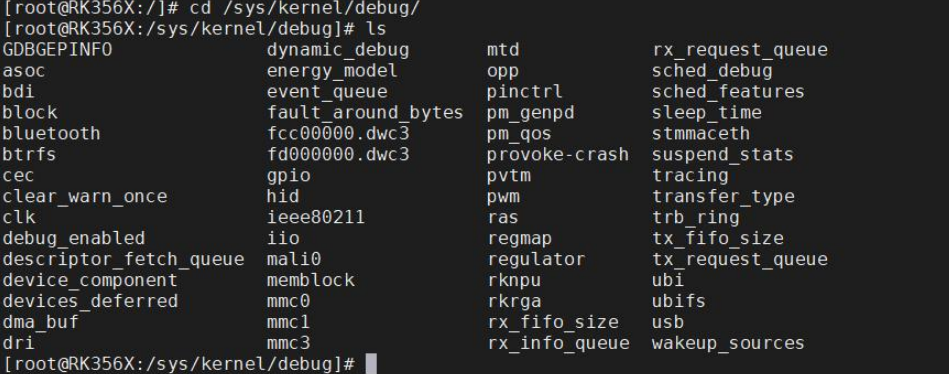
If the directory in the above figure/sys/kernel/debugthere are no files under the directory, you need to configure debugfs in the Linux kernel source code and checkDebug FilesystemAfter configuration, recompile the kernel source code and flash the kernel image.
1234567 | Kernel hacking ---> Generic Kernel Debugging Instruments ---> -*- Debug Filesystem Debugfs default access (Access normal) ---> (X) Access normal ( ) Do not register debugfs as filesystem ( ) No access |
If there is no debugfs, you can use the following command to mount it:
1 | mount -t debugfs none /sys/kernel/debug/ |
If there is debugfs, you can use the following command to view GPIO information.
1 | cat /sys/kernel/debug/gpio |
enter/sys/kernel/debug/pinctrlIn the directory, you can obtain debug information about the GPIO controller. Under this directory, there are usually the following files and directories:
/sys/kernel/debug/pinctrl/*/pinmux-pinsThese files list the pin multiplexing configuration for each GPIO pin. You can view the function mode, pin mux selection, and other related configuration information for each pin. We enter/sys/kernel/debug/pinctrl/pinctrl-rockchip-pinctrl/Next, entercat pinmux-pins, as shown in the figure below:

/sys/kernel/debug/pinctrl/*/pinsThese files list the GPIO pin numbers, allowing you to view the GPIO numbers. We enter/sys/kernel/debug/pinctrl/pinctrl-rockchip-pinctrl/Next, entercat pins, as shown in the figure below:

/sys/kernel/debug/pinctrl/*/gpio-rangesThese files list the GPIO ranges supported by each GPIO controller.
You can view the GPIO number range and the corresponding controller name. We enter/sys/kernel/debug/pinctrl/pinctrl-rockchip-pinctrl/Next, entercat gpio-ranges, as shown in the figure below:

/sys/kernel/debug/pinctrl/*/pinmux-functionsThese files list the name of each function mode and the GPIO pins associated with it. You can view the name of each function mode and the corresponding pin list. We enter/sys/kernel/debug/pinctrl/pinctrl-rockchip-pinctrl/Next, entercat pinmux-functions, as shown in the figure below:

/sys/kernel/debug/pinctrl/*/pingroupsThis path provides information about the pin groups used to configure and control the GPIO pins on the system. We enter/sys/kernel/debug/pinctrl/pinctrl-rockchip-pinctrl/Next, entercat pingroups, as shown in the figure below:

/sys/kernel/debug/pinctrl/*/pinconf-pinsThese files contain configuration information for GPIO pins, such as input/output mode, pull-up/pull-down settings, etc. You can view and modify the electrical properties of GPIO for debugging and configuration. We enter/sys/kernel/debug/pinctrl/pinctrl-rockchip-pinctrl/Next, entercat pinconf-pins, as shown in the figure below:

GPIO Subsystem API
In the current Linux kernel mainline, there are two versions of the GPIO (General Purpose Input/Output) subsystem. Here, the two versions are distinguished as the new version and the old version. The new GPIO subsystem interface is implemented based on descriptors (descriptor-based), while the old GPIO subsystem interface is implemented based on integers (integer-based). In the Linux kernel, to maintain backward compatibility, the old interface is still supported in the latest kernel versions. Over time, the new GPIO subsystem interface will become more complete and eventually completely replace the old version.
The new GPIO subsystem interface needs to be used in conjunction with the Device Tree. Using the Device Tree and the new GPIO interface allows more flexible configuration and management of GPIO resources in the system, providing better scalability and portability. ThereforeWithout a device tree, the new GPIO interface cannot be used.。
An obvious difference is that the new GPIO subsystem interface uses agpiod_as a prefix in the function naming convention, while the old GPIO subsystem interface used to usegpio_Function naming convention as a prefix.
gpio_desc structure
12345678910111213141516171819202122232425262728293031323334 | struct gpio_desc { struct gpio_device *gdev; // GPIO device structure unsigned long flags; // Flag bit, used to represent different attributes/* flag symbols are bit numbers */ /* Connection label */ const char *label; // Indicates the label or name of the GPIO /* Name of the GPIO */ const char *name; // GPIO name struct device_node *hog; /* debounce period in microseconds */ unsigned int debounce_period_us;}; |
gpio_device structure
12345678910111213141516171819202122232425262728293031323334353637383940414243444546474849505152535455 | /** * struct gpio_device - internal state container for GPIO devices * @id: numerical ID number for the GPIO chip * @dev: the GPIO device struct * @chrdev: character device for the GPIO device * @mockdev: class device used by the deprecated sysfs interface (may be * NULL) * @owner: helps prevent removal of modules exporting active GPIOs * @chip: pointer to the corresponding gpiochip, holding static * data for this device * @descs: array of ngpio descriptors. * @ngpio: the number of GPIO lines on this GPIO device, equal to the size * of the @descs array. * @base: GPIO base in the DEPRECATED global Linux GPIO numberspace, assigned * at device creation time. * @label: a descriptive name for the GPIO device, such as the part number * or name of the IP component in a System on Chip. * @data: per-instance data assigned by the driver * @list: links gpio_device:s together for traversal * * This state container holds most of the runtime variable data * for a GPIO device and can hold references and live on after the * GPIO chip has been removed, if it is still being used from * userspace. */struct gpio_device { int id; // GPIO device ID. Each GPIO device can have a unique ID. struct device dev;// corresponding device structure pointer struct cdev chrdev;// Character device structure, used to implement the character device interface for GPIO devices. struct device *mockdev;// Simulated device structure pointer, used to represent the simulated device structure of a GPIO device. struct module *owner;// Pointer to the kernel module that owns this GPIO device struct gpio_chip *chip;// Pointer to the corresponding GPIO chip structure, indicating the GPIO chip (GPIO controller) structure associated with the GPIO device. struct gpio_desc *descs;// GPIO descriptor array pointer. Each GPIO descriptor is used to describe the attributes and state of the GPIO. int base;// Starting value of GPIO number u16 ngpio;// Number of GPIO const char *label;// GPIO device label void *data;// Data pointer associated with GPIO device struct list_head list;// Used to link the GPIO device structure into the linked list struct blocking_notifier_head notifier; /* * If CONFIG_PINCTRL is enabled, then gpio controllers can optionally * describe the actual pin range which they serve in an SoC. This * information would be used by pinctrl subsystem to configure * corresponding pins for gpio usage. */ /* * If enabled CONFIG_PINCTRL Options,GPIO The controller can choose to describe them in SoC The actual pin range in the service。 * This information will be pinctrl The subsystem is used to configure the corresponding GPIO pin。 */ struct list_head pin_ranges;// Linked list describing the pin range of the GPIO controller}; |
Among the above series of parameters, the one to focus on isstruct gpio_chip *chipThis structure represents the GPIO chip (GPIO controller) structure associated with the GPIO device.
gpio_chip structure
123456789101112131415161718192021222324252627282930313233343536373839404142434445464748495051525354555657585960616263646566676869707172737475767778798081828384858687888990919293949596979899100101102103104105106107108109110111112113114115116117118119 | struct gpio_chip { const char *label;// GPIO chip label struct gpio_device *gpiodev;// GPIO device struct device *parent;// Parent device pointer struct module *owner;// Owner module pointer int (*request)(struct gpio_chip *gc, unsigned int offset);// Request GPIO void (*free)(struct gpio_chip *gc, unsigned int offset);// Release GPIO int (*get_direction)(struct gpio_chip *gc, unsigned int offset);// Get GPIO direction int (*direction_input)(struct gpio_chip *gc, unsigned int offset);// Set GPIO as input int (*direction_output)(struct gpio_chip *gc, unsigned int offset, int value);// Set GPIO as output int (*get)(struct gpio_chip *gc, unsigned int offset);// Get GPIO value int (*get_multiple)(struct gpio_chip *gc, unsigned long *mask, unsigned long *bits);// Get values of multiple GPIOs void (*set)(struct gpio_chip *gc, unsigned int offset, int value);// Set GPIO value void (*set_multiple)(struct gpio_chip *gc, unsigned long *mask, unsigned long *bits);// Set multiple GPIOs int (*set_config)(struct gpio_chip *gc, unsigned int offset, unsigned long config);// Set GPIO configuration int (*to_irq)(struct gpio_chip *gc, unsigned int offset);// Convert GPIO to interrupt void (*dbg_show)(struct seq_file *s, struct gpio_chip *gc);// Display GPIO in debug information int (*init_valid_mask)(struct gpio_chip *gc, unsigned long *valid_mask, unsigned int ngpios); int (*add_pin_ranges)(struct gpio_chip *gc); int base;// Base value of GPIO numbering u16 ngpio;// Number of GPIO const char *const *names;// Array of GPIO names bool can_sleep; unsigned long (*read_reg)(void __iomem *reg); void (*write_reg)(void __iomem *reg, unsigned long data); bool be_bits; void __iomem *reg_dat; void __iomem *reg_set; void __iomem *reg_clr; void __iomem *reg_dir_out; void __iomem *reg_dir_in; bool bgpio_dir_unreadable; int bgpio_bits; spinlock_t bgpio_lock; unsigned long bgpio_data; unsigned long bgpio_dir; /* * With CONFIG_GPIOLIB_IRQCHIP we get an irqchip inside the gpiolib * to handle IRQs for most practical cases. */ /** * @irq: * * Integrates interrupt chip functionality with the GPIO chip. Can be * used to handle IRQs for most practical cases. */ struct gpio_irq_chip irq; /** * @valid_mask: * * If not %NULL holds bitmask of GPIOs which are valid to be used * from the chip. */ unsigned long *valid_mask; /* * If CONFIG_OF is enabled, then all GPIO controllers described in the * device tree automatically may have an OF translation */ /** * @of_node: * * Pointer to a device tree node representing this GPIO controller. */ struct device_node *of_node; /** * @of_gpio_n_cells: * * Number of cells used to form the GPIO specifier. */ unsigned int of_gpio_n_cells; /** * @of_xlate: * * Callback to translate a device tree GPIO specifier into a chip- * relative GPIO number and flags. */ int (*of_xlate)(struct gpio_chip *gc, const struct of_phandle_args *gpiospec, u32 *flags); ANDROID_KABI_RESERVE(1); ANDROID_KABI_RESERVE(2);}; |
struct gpio_chip *chipThis structure is used to describe the attributes and operation functions of the GPIO chip. Through function pointers, the corresponding functions can be called to request, release, set, and get the state and value of GPIOs, thereby achieving control and management of GPIOs. It should be noted that the series of functions in this structure do not need to be filled in by us; this work is done by the chip manufacturer’s engineers. We only need to learn how to use the corresponding API functions of the new GPIO subsystem.
Get a single GPIO descriptor
gpiod_get()
Function prototype
12345 | struct gpio_desc *__must_check gpiod_get( struct device *dev, const char *con_id, enum gpiod_flags flags); |
Header file
1 | |
Function
Obtain a required GPIO descriptor based on the device and connection identifier (con_id), and configure its mode according to the specified flags.
Parameters
dev: points to the associated devicestruct devicepointer.con_id: Connection identifier (connection ID), usually defined in the Device Tree, used to match a specific GPIO.flags: GPIO configuration flag, type isenum gpiod_flags, commonly used values include:GPIOD_INorGPIOD_INPUT: Configured as input.GPIOD_OUT_LOW/GPIOD_OUT_HIGH(for old versionGPIOD_OUTPUT): Configured as output, default initial level is low/high.GPIOD_ACTIVE_LOW: Logic high corresponds to physical low level (inverted).GPIOD_OPEN_DRAIN: Open-drain output.GPIOD_OPEN_SOURCE: Open-source output.
⚠️ Note: Recommended for use with modern kernels
GPIOD_OUT_LOW/GPIOD_OUT_HIGHsubstituteGPIOD_OUTPUT, because the latter does not specify an initial level.
Example device tree fragment
123456789 | / { my_device: my-device@0 { compatible = "myvendor,my-device"; /* Define 3 GPIOs, corresponding to indices 0, 1, and 2 respectively. */ my-gpios = <&gpio1 5 GPIO_ACTIVE_HIGH>, // index 0 <&gpio1 6 GPIO_ACTIVE_LOW>, // index 1 <&gpio2 12 GPIO_ACTIVE_HIGH>; // index 2 };}; |
Return value
- Success: return pointer
struct gpio_descthe pointer. - Failure: returns
ERR_PTR()Encoding error pointer (e.g.-ENOENT,-EPROBE_DEFERetc.),is not NULL。
✅ Usage suggestion: should use
IS_ERR()Determine whether the return value is an error, rather than checking.NULL。
gpiod_get_index()
Function prototype
123456 | struct gpio_desc *__must_check gpiod_get_index( struct device *dev, const char *con_id, unsigned int idx, enum gpiod_flags flags); |
Function
Obtain device, connection identifier, and indexidxThe corresponding GPIO descriptor. Applies to onecon_idCorresponds to multiple GPIOs (such as array-type GPIO groups like “leds”, “buttons”, etc.).
Parameters
idx: GPIO index in this connection (starting from 0).
Return value
- same
gpiod_get: Successful returngpio_desc*, on failure, returns an error pointer.
gpiod_get_optional()
Function prototype
12345 | struct gpio_desc *__must_check gpiod_get_optional( struct device *dev, const char *con_id, enum gpiod_flags flags); |
Function
Attempt to get the specified GPIO, but if the GPIO is not defined in the device tree, thennot considered an error, but rather returnsNULL。
Applicable scenarios
Used for optional GPIO (e.g., some hardware versions have it, some don’t).
Return value
- Successfully obtained: Return
struct gpio_desc*。 - Undefined or nonexistent: return
NULL。 - Other errors (such as defer): return error pointer (need to use
IS_ERR()check).
✅ Safe usage methods:
gpiod_get_index_optional()
Function prototype
123456 | struct gpio_desc *__must_check gpiod_get_index_optional( struct device *dev, const char *con_id, unsigned int idx, enum gpiod_flags flags); |
Function
gpiod_get_indexOptional version: if the GPIO at the specified index does not exist, no error is reported, returnNULL。
Return value
- Exists and succeeds:
gpio_desc* - Does not exist:
NULL - Other errors: bad pointer (requires
IS_ERR()judgment)
gpiod_put()
Function prototype
1 | void gpiod_put(struct gpio_desc *desc); |
Header file
1 | |
Function
Release a passgpiod_get()、gpiod_get_index()、gpiod_get_optional()orgpiod_get_index_optional()Obtained GPIO descriptor.
This function will:
- Release the reference to this GPIO;
- If this is the last reference, restore the GPIO to an unused state (such as releasing interrupts, unmapping, etc.);
- It will not automatically change the GPIO level or direction (unless the underlying driver implements special behavior).
⚠️ Note: Even if GPIO is “optional” (via
_optionalfunction gets), as long as the return value is non-NULLAnd if it is not an error pointer, it should be called.gpiod_put()。
Parameters
desc: points to the object to be releasedstruct gpio_descthe pointer.- How can
NULL, the function safely does nothing (Allow passing NULL)。 - If it is an error pointer (such as
ERR_PTR(-ENOENT)), should not be calledgpiod_put()。
- How can
example
The new version of the GPIO subsystem API interface must be used in conjunction with the device tree, so it is necessary to multiplex the pin used to obtain the GPIO descriptor into GPIO mode in the device tree. Here, select pin 1 of the 20-pin GPIO header on the back of the RK3568 development board, and the corresponding silkscreen on the right isI2C3_SDA_M0。

It can be seen that the network label of pin 1 isI2C3_SDA_M0, then open the core board schematic, search according to this net label, and the found core board content is as follows:

First, according to the multiplexing functions in the above figure, check whether the pin has already been multiplexed in the device tree. After ensuring that the pin has no multiplexing,topeet-rk3568-linux.dtsiAdd content to the device tree by appending the following at the end of the root node:
123456 | my_gpio: gpio1_a0{ compatible = "even629,mygpio"; my-gpios = <&gpio1 RK_PA0 GPIO_ACTIVE_HIGH>; pinctrl-names = "default"; pinctrl-0 = <&mygpio_ctrl>;}; |
compatible: Used to specify the device’s compatibility string, matching the value in the driver.my-gpios: Specifies the GPIO associated with this device.&gpio1Represents the handle of the GPIO controller,RK_PA0is the resource descriptor (resource specifier) associated with this GPIO,GPIO_ACTIVE_HIGHIndicates that the default level of GPIO is high.
Note that here it must be
my-gpiosrather thangpios, must have the middle one"-"
pinctrl-namesandpinctrl-0: Used to specify the pin controller (pinctrl) configuration.pinctrl-namesIndicates the name of the pin controller configuration, here it is “default”.pinctrl-0Specifies the pin controller handle associated with this configuration, here it is&mygpio_ctrl。
Then find the pinctrl child node.
12345678910111213141516171819 | &pinctrl { rk_485{ rk_485_gpio:rk-485-gpio { rockchip,pins = <0 RK_PC6 RK_FUNC_GPIO &pcfg_pull_none>; }; }; dht11{ dht11_gpio:dht11-gpio { rockchip,pins = <3 2 RK_FUNC_GPIO &pcfg_pull_none>; }; }; // added by even629 mygpio{ mygpio_ctrl:mygpio_ctrl{ rockchip,pins = <1 RK_PA0 RK_FUNC_GPIO &pcfg_pull_none>; }; }; }; |
1Indicates the pin index.RK_PA0Indicates the resource descriptor, used to identify the physical resource associated with the pin, indicating the functional group to which the pin belongs.RK_FUNC_GPIOIndicates setting the pin function to GPIO.&pcfg_pull_noneIndicates the pin is configured with no pull-up/pull-down.
Driver
1234567891011121314151617181920212223242526272829303132333435363738394041424344454647484950515253545556575859606162636465666768697071 | struct gpio_desc *mygpiod1;struct gpio_desc *mygpiod2;static int gpiod_test_pdrv_probe(struct platform_device *pdev){ int ret = 0; int gpio_num; pr_info("%s\n", __func__); mygpiod1 = gpiod_get_optional(&pdev->dev, "my", GPIOD_IN); if (IS_ERR_OR_NULL(mygpiod1)) { dev_err(&pdev->dev, "gpiod_get_optional failed: errno %ld\n", PTR_ERR(mygpiod1)); ret = PTR_ERR(mygpiod1); goto err_get_mygpiod; } gpio_num = desc_to_gpio(mygpiod1); pr_info("get gpio num: %d\n", gpio_num); gpiod_put(mygpiod1); mygpiod2 = gpiod_get_index_optional(&pdev->dev, "my", 0, GPIOD_IN); if (IS_ERR_OR_NULL(mygpiod2)) { dev_err(&pdev->dev, "gpiod_get_index_optional failed: errno %ld\n", PTR_ERR(mygpiod2)); ret = PTR_ERR(mygpiod2); goto err_get_mygpiod; } gpio_num = desc_to_gpio(mygpiod2); pr_info("get gpio num: %d\n", gpio_num); gpiod_put(mygpiod2);err_get_mygpiod: return ret;}static int gpiod_test_pdrv_remove(struct platform_device *pdev){ pr_info("%s\n", __func__); return 0;}const struct of_device_id match_table_id[] = { { .compatible = "even629,mygpio" },};static struct platform_driver gpiod_test_pdrv = { .driver = { .name = "test_gpiod_test", .owner = THIS_MODULE, .of_match_table = match_table_id, }, .probe = gpiod_test_pdrv_probe, .remove = gpiod_test_pdrv_remove, };module_platform_driver(gpiod_test_pdrv);MODULE_LICENSE("GPL");MODULE_AUTHOR("even629<asqwgo@outlook.com>");MODULE_DESCRIPTION("This is a test sample for gpiod"); |
Test:
12345 | root@topeet:/root# insmod gpiod_test.ko[ 143.125511] gpiod_test: loading out-of-tree module taints kernel.[ 143.126961] gpiod_test_pdrv_probe[ 143.127094] get gpio num: 32[ 143.127121] get gpio num: 32 |
GPIO operation functions
The header file is unified as:#include <linux/gpio/consumer.h>
Get GPIO direction
function
1 | int gpiod_get_direction(struct gpio_desc *desc); |
Function
Query whether the GPIO is currently configured as input or output.
Return value
GPIO_LINE_DIRECTION_IN(0): Input modeGPIO_LINE_DIRECTION_OUT(1): Output mode- Negative: error code (e.g.
-EINVAL)
Configure GPIO direction
Configure as input
1 | int gpiod_direction_input(struct gpio_desc *desc); |
Configure as output (with initial level)
1 | int gpiod_direction_output(struct gpio_desc *desc, int value); |
value: 0 (low level) or 1 (high level)
Return value (same for both)
0: success- Negative: failure (e.g.
-EINVAL,-ENODEV)
Notes.
- The direction must be set correctly before reading or writing the GPIO.
- Output mode requires specifying an initial level to avoid glitches.
Read GPIO level (input)
1 | int gpiod_get_value(const struct gpio_desc *desc); |
Function
Read the current physical level of the GPIO pin (consideringACTIVE_LOWthe logical value after mapping).
Return value
0: logic low level1: logic high level- Negative: error (rare, usually occurs only on hardware anomalies)
Description
- Even if the GPIO is configured as output, its output state can be read back (supported by some controllers).
- The returned value islogical value, automatically handling the device tree’s
GPIO_ACTIVE_LOWinversion.
Set GPIO level (output)
1 | void gpiod_set_value(struct gpio_desc *desc, int value); |
Parameters
value: 0 (logic low) or 1 (logic high)
Return value
- None (
void)
key prerequisite
- must first configure the GPIO as output mode(through
gpiod_direction_output())。 - also usinglogical value, the kernel automatically handles
ACTIVE_LOWinversion.
Convert GPIO to interrupt number
1 | int gpiod_to_irq(const struct gpio_desc *desc); |
Function
Get the Linux interrupt number (IRQ number) associated with this GPIO, used to register an interrupt handler.
Return value
≥ 0: valid interrupt number- Negative: interrupt not supported or conversion failed (e.g.,
-ENXIO)
example
1234567891011121314151617181920212223242526272829303132333435363738394041424344454647484950515253545556575859606162636465666768697071727374757677787980818283848586 | static struct gpio_desc *mygpiod1;static int test_pdrv_probe(struct platform_device *pdev){ int ret = 0; int direct, value, irq; pr_info("%s\n", __func__); mygpiod1 = gpiod_get_optional(&pdev->dev, "my", GPIOD_OUT_LOW); if (IS_ERR_OR_NULL(mygpiod1)) { dev_err(&pdev->dev, "gpiod_get_optional error\n"); ret = PTR_ERR(mygpiod1); goto err_get_gpiod; } // Set to high level gpiod_set_value(mygpiod1, 1); // Get direction direct = gpiod_get_direction(mygpiod1); switch (direct) { case GPIO_LINE_DIRECTION_IN: pr_info("direction is input\n"); break; case GPIO_LINE_DIRECTION_OUT: pr_info("direction is output\n"); break; default: dev_err(&pdev->dev, "unknown direction\n"); ret = -EFAULT; goto err_op; } // Read current value value = gpiod_get_value(mygpiod1); pr_info("value is %d\n", value); // Get interrupt number irq = gpiod_to_irq(mygpiod1); if (irq < 0) { dev_err(&pdev->dev, "get irq error"); ret = -EFAULT; goto err_op; } pr_info("irq is %d\n", irq);err_op: gpiod_put(mygpiod1);err_get_gpiod: return ret;}static int test_pdrv_remove(struct platform_device *pdev){ gpiod_put(mygpiod1); return 0;}static const struct of_device_id match_table[] = { { .compatible = "even629,mygpio",} };static struct platform_driver test_pdrv = { .driver = { .name = "test_gpio", .owner = THIS_MODULE, .of_match_table = match_table, }, .probe = test_pdrv_probe, .remove = test_pdrv_remove,};module_platform_driver(test_pdrv);MODULE_LICENSE("GPL");MODULE_AUTHOR("even629<asqwgo@outlook.com>");MODULE_DESCRIPTION("This is a test sample for gpiod"); |
Test:
12345678910111213141516 | root@topeet:/root# insmod gpiod_operation_test.ko[ 1587.965351] gpiod_operation_test: loading out-of-tree module taints kernel.[ 1587.966739] test_pdrv_probe[ 1587.966862] direction is output[ 1587.966873] value is 1[ 1587.966931] irq is 125root@topeet:/root# lsmodModule Size Used bygpiod_operation_test 16384 0rtk_btusb 61440 08723du 1568768 0root@topeet:/root# rmmod gpiod_operation_test.koroot@topeet:/root# lsmodModule Size Used byrtk_btusb 61440 08723du 1568768 0 |
Level-3 node operation functions
In the previous examples, we obtained the GPIO descriptions of level-2 nodes. So how do we obtain the GPIO descriptions of the two level-3 nodes led1 and led2 below?
12345678910111213 | my_gpio:gpio1_a0 { compatible = "even629,mygpio"; led1{ my-gpios = <&gpio1 RK_PA0 GPIO_ACTIVE_HIGH>, <&gpio1 RK_PB1 GPIO_ACTIVE_HIGH>; pinctrl-names = "default"; pinctrl-0 = <&mygpio_ctrl>; }; led2{ my-gpios = <&gpio1 RK_PB0 GPIO_ACTIVE_HIGH>; };}; |
device_get_child_node_count()
Function: Get the number of child nodes of a device
Function prototype
1 | unsigned int device_get_child_node_count(struct device *dev); |
Header file
1 | |
Parameters
dev: pointing to the parent devicestruct devicepointer.
Return value
- Success: Returns the number of child nodes (an unsigned integer ≥ 0).
- No child nodes or failure: returns
0。
Description
- Used to determine whether a device contains child nodes in the device tree (such as sub-devices like LEDs, buttons, etc.).
- Often used to dynamically allocate resources or decide whether to enter child node traversal logic.
example
1234 | if (device_get_child_node_count(&pdev->dev) == 0) { dev_info(&pdev->dev, "No child nodes\n"); return 0;} |
device_get_next_child_node()
Function: Traverse all child nodes of a device
Function prototype
1234 | struct fwnode_handle *device_get_next_child_node( struct device *dev, struct fwnode_handle *child); |
Header file
1 | |
Parameters
dev: parent device pointer.child: current child node pointer; on first call, passNULL。
Return value
- Success: returns the next child node’s
fwnode_handle * - End of traversal: returns
NULL
Traversal mode (standard usage)
123456789101112 | struct fwnode_handle *child = NULL;while ((child = device_get_next_child_node(&pdev->dev, child))) { // Process child nodes, e.g., get their GPIO struct gpio_desc *desc = fwnode_get_named_gpiod(child, "gpios", 0, GPIOD_OUT_LOW, "sub-gpio"); if (!IS_ERR(desc)) { /* Use desc */ gpiod_put(desc); } // Note: There is no need to manually release child; the kernel manages it automatically.} |
🔔 Note:
fwnode_handleManaged by the kernel,do not manually release。- Automatically stops after traversal; no additional cleanup required.
fwnode_get_named_gpiod()
Function: Get a named GPIO from the specified firmware node (e.g., a device tree child node).
Function prototype
1234567 | struct gpio_desc *fwnode_get_named_gpiod( struct fwnode_handle *fwnode, const char *propname, int index, enum gpiod_flags dflags, const char *label); |
Header file
1 | |
Parameters
| Parameters | Description |
|---|---|
fwnode | pointing to the child nodefwnode_handle(usually fromdevice_get_next_child_node()) |
propname | GPIO property name (e.g.,"led-gpios"、"enable-gpios"、"my-gpios") |
index | index in the property (0 means the first GPIO) |
dflags | Initialization flags: •GPIOD_IN•GPIOD_OUT_LOW•GPIOD_OUT_HIGH•GPIOD_ASIS(do not configure direction) |
label | GPIO label (for debugging, e.g.,"my-led") |
Return value
- On success: returns
struct gpio_desc * - Failure: returns
ERR_PTR(...)(Note:is not NULL)
⚠️ Important: the function returns error pointer (ERR_PTR), use
IS_ERR()to check, rather than checkingNULL。
Use case
When the device tree structure is ‘parent device + multiple child nodes’, and each child node defines its own GPIO (e.g., multiple LEDs):
1234567891011121314
my_device { compatible = "myvendor,my-device"; #address-cells = <1>; #size-cells = <0>; led@0 { reg = <0>; led-gpios = <&gpio1 10 GPIO_ACTIVE_HIGH>; }; led@1 { reg = <1>; led-gpios = <&gpio1 11 GPIO_ACTIVE_LOW>; };};
Driver:
12345 | desc = fwnode_get_named_gpiod(child, "led-gpios", 0, GPIOD_OUT_LOW, "my-led");if (IS_ERR(desc)) { dev_err(dev, "Failed to get GPIO: %ld\n", PTR_ERR(desc)); return PTR_ERR(desc);} |
Complete example
Device tree:
1234567891011121314151617181920212223242526272829303132333435363738 | /{ my_gpio:gpio1_a0{ compatible = "even629,mygpio"; led1{ my-gpios = <&gpio1 RK_PA0 GPIO_ACTIVE_HIGH>, <&gpio1 RK_PB1 GPIO_ACTIVE_HIGH>; pinctrl-names = "default"; pinctrl-0 = <&mygpio_ctrl>; }; led2{ my-gpios = <&gpio1 RK_PB0 GPIO_ACTIVE_HIGH>; }; };}; &pinctrl { rk_485{ rk_485_gpio:rk-485-gpio { rockchip,pins = <0 RK_PC6 RK_FUNC_GPIO &pcfg_pull_none>; }; }; dht11{ dht11_gpio:dht11-gpio { rockchip,pins = <3 2 RK_FUNC_GPIO &pcfg_pull_none>; }; }; // added by even629 mygpio{ mygpio_ctrl:mygpio_ctrl{ rockchip,pins = <1 RK_PA0 RK_FUNC_GPIO &pcfg_pull_none>, <1 RK_PB1 RK_FUNC_GPIO &pcfg_pull_none>; }; }; }; |
Driver:
1234567891011121314151617181920212223242526272829303132333435363738394041424344454647484950515253545556575859606162 | int test_pdrv_probe(struct platform_device *pdev){ int ret = 0; u32 count; struct device *dev = &pdev->dev; struct fwnode_handle *child = NULL; count = device_get_child_node_count(dev); if (count == 0) { dev_info(dev, "No child nodes\n"); return 0; } dev_info(dev, "Found %u child nodes\n", count); while ((child = device_get_next_child_node(dev, child))) { struct gpio_desc *desc; desc = fwnode_get_named_gpiod(child, "my-gpios", 0, GPIOD_OUT_LOW, "test-child-gpio"); if (IS_ERR(desc)) { dev_warn(dev, "Skip child: failed to get GPIO (%ld)\n", PTR_ERR(desc)); continue; } gpiod_set_value(desc, 1); msleep(10); gpiod_set_value(desc, 0); gpiod_put(desc); } return ret;}int test_pdrv_remove(struct platform_device *pdev){ return 0;}static const struct of_device_id match_table[] = { { .compatible = "even629,mygpio" } };static struct platform_driver test_pdrv = { .driver = { .name = "third_level_test", .owner = THIS_MODULE, .of_match_table = match_table }, .probe = test_pdrv_probe, .remove = test_pdrv_remove,};module_platform_driver(test_pdrv);MODULE_LICENSE("GPL");MODULE_AUTHOR("even629<asqwgo@outlook.com>");MODULE_DESCRIPTION("This is a test sample for third level devicetree"); |
Test:
12345678 | root@topeet:/root# insmod third_level_gpiod_operation.ko[ 287.444221] third_level_test gpio1_a0: Found 2 child nodesroot@topeet:/root# lsmodModule Size Used bythird_level_gpiod_operation 16384 0rtk_btusb 61440 08723du 1568768 0root@topeet:/root# rmmod third_level_gpiod_operation.ko |
GPIO subsystem and pinctrl
The header file is unified as:
1 | |
Get the pinctrl instance
1 | struct pinctrl *pinctrl_get(struct device *dev); |
Function
Get the devicedevThe associated pinctrl controller instance.
Parameters
dev: pointer to the devicestruct device(usually&pdev->dev)。
Return value
- On success: returns
struct pinctrl * - On failure or if the device has no pinctrl support: returns
ERR_PTR(...)(Note: not NULL)
⚠️ Important: the function returns error pointer (ERR_PTR), use
IS_ERR()to check!
Usage example
12345 | p = pinctrl_get(&pdev->dev);if (IS_ERR(p)) { dev_err(&pdev->dev, "Failed to get pinctrl\n"); return PTR_ERR(p);} |
Release pinctrl instance
function
1 | void pinctrl_put(struct pinctrl *p); |
Function
Release thepinctrl_get()obtained pinctrl instance, decrement the reference count, and release resources if necessary.
Parameters
p: the pinctrl to be releasedstruct pinctrl *pointer.
Notes.
- Allows passing
NULLorERR_PTR(it will be safely handled internally). - Usually in the driver
remove()or error path.
example
12 | if (!IS_ERR(p)) pinctrl_put(p); |
Look up pinctrl state
function
1 | struct pinctrl_state *pinctrl_lookup_state(struct pinctrl *p, const char *name); |
Function
In the pinctrl instanceplook up the namednamestate (such as"default"、"sleep")。
Parameters
p: Valid pinctrl instance pointer.name: State name (string), must match the state name defined in the device tree.
Return value
- On success: returns
struct pinctrl_state * - Failure (not found or error): returns
ERR_PTR(...)
⚠️ Also need to use
IS_ERR()to check!
example
12345 | state = pinctrl_lookup_state(p, "default");if (IS_ERR(state)) { dev_err(&pdev->dev, "Failed to lookup 'default' state\n"); return PTR_ERR(state);} |
Apply pinctrl state to hardware
function
1 | int pinctrl_select_state(struct pinctrl *p, struct pinctrl_state *s); |
Function
Apply the specified statesto the hardware pin controller, actually applying pin multiplexing and electrical settings.
Parameters
p: pinctrl instances: target state
Return value
0: success- Negative: error code (e.g.
-EINVAL,-ENODEV)
example
12345 | ret = pinctrl_select_state(p, state);if (ret) { dev_err(&pdev->dev, "Failed to select pinctrl state: %d\n", ret); return ret;} |
example
Device tree:
1234567891011121314151617181920 | my_device: my-device@0 { compatible = "even629,my-device"; pinctrl-names = "default", "sleep"; my-gpios = <&gpio1 RK_PA0 GPIO_ACTIVE_HIGH>, <&gpio1 RK_PB1 GPIO_ACTIVE_HIGH>; pinctrl-0 = <&my_pins_default>; pinctrl-1 = <&my_pins_sleep>; /* Other properties */};&pinctrl { my_pins_default: my-pins-default { rockchip,pins = <1 RK_PA0 RK_FUNC_GPIO &pcfg_pull_up>, <1 RK_PB1 RK_FUNC_GPIO &pcfg_pull_up>; }; my_pins_sleep: my-pins-sleep { rockchip,pins = <1 RK_PA0 RK_FUNC_GPIO &pcfg_pull_down>, <1 RK_PB1 RK_FUNC_GPIO &pcfg_pull_down>; };}; |
🔑 Key points:
pinctrl-namesDefine a list of state namespinctrl-0,pinctrl-1States corresponding to indices 0 and 1- In the driver, by name (e.g.
"default") look up the state
Driver:
12345678910111213141516171819202122232425262728293031323334353637383940414243444546474849505152535455565758596061626364656667686970717273747576 | static struct pinctrl *pinctrl;int test_pdrv_probe(struct platform_device *pdev){ int ret = 0; struct device *dev = &pdev->dev; struct pinctrl_state *default_stat, *sleep_stat; // 1. Get pinctrl pinctrl = pinctrl_get(dev); if (IS_ERR(pinctrl)) { dev_err(dev, "Failed to get pinctrl"); return PTR_ERR(pinctrl); } // 2. Look up state default_stat = pinctrl_lookup_state(pinctrl, "default"); if (IS_ERR(default_stat)) { dev_err(dev, "Failed to lookup 'default' state\n"); ret = PTR_ERR(default_stat); goto err; } sleep_stat = pinctrl_lookup_state(pinctrl, "sleep"); if (IS_ERR(sleep_stat)) { dev_err(dev, "Failed to lookup 'sleep' state\n"); ret = PTR_ERR(sleep_stat); goto err; } // 3. Apply state ret = pinctrl_select_state(pinctrl, sleep_stat); if (ret < 0) { dev_err(dev, "Failed to select 'sleep' state\n"); ret = -EFAULT; goto err; } return ret;err: pinctrl_put(pinctrl); return ret;}int test_pdrv_remove(struct platform_device *pdev){ pinctrl_put(pinctrl); return 0;}const struct of_device_id match_table[] = { { .compatible = "even629,test-device" },};static struct platform_driver test_pdrv = { .driver = { .name = "test-gpio-pinctrl", .owner = THIS_MODULE, .of_match_table = match_table, }, .probe = test_pdrv_probe, .remove = test_pdrv_remove,};module_platform_driver(test_pdrv);MODULE_LICENSE("GPL");MODULE_AUTHOR("even629<asqwgo@outlook.com>");MODULE_DESCRIPTION("This is test sample"); |
Supplementary notes
| Scenario | Recommendation |
|---|---|
| Only default configuration is required. | There is no need to explicitly call the pinctrl API; the kernel will apply it automatically during probe.pinctrl-0(ifpinctrl-namescontains"default") |
| dynamic switching state | such as switching to during suspend/resume"sleep"Status |
| Error handling | All functions that return a pointer may returnERR_PTR, be sure to useIS_ERR()Check |
| Resource release | Beforeremove()call inpinctrl_put() |
Implement dynamic switching of pin multiplexing function
Here, we still use pin 1 of the 20-pin GPIO header on the back of the RK3568 baseboard to implement the dynamic pin multiplexing switching function described in this chapter.
1234567 | gpio1_a0:gpio1-a0{ compatible = "even629,mygpio"; my-gpios = <&gpio1 RK_PA0 GPIO_ACTIVE_HIGH>; pinctrl-names = "mygpio_func1", "mygpio_func2"; pinctrl-0 = <&mygpio_ctrl>; pinctrl-1 = <&i2c3_sda>;}; |
pinctrl-namesIndicates the name of the pin controller configuration. There are two values here, corresponding to mux 1 and mux 2 respectively.pinctrl-0Specifies the pin controller handle associated with this configuration, here it is&mygpio_ctrl, indicating that it is muxed as a GPIO function.pinctrl-1Specifies the pin controller handle associated with this configuration, here it is&i2c3_sda, indicating that it is muxed asi2c3_sdafunction.
123456789101112131415161718192021222324 | &pinctrl { rk_485{ rk_485_gpio:rk-485-gpio { rockchip,pins = <0 RK_PC6 RK_FUNC_GPIO &pcfg_pull_none>; }; }; dht11{ dht11_gpio:dht11-gpio { rockchip,pins = <3 2 RK_FUNC_GPIO &pcfg_pull_none>; }; }; // added by even629 mygpio_func1{ mygpio_ctrl:mygpio-ctrl{ rockchip,pins = <1 RK_PA0 RK_FUNC_GPIO &pcfg_pull_none>; }; }; mygpio_func2{ i2c3_sda:i2c3-sda{ rockchip,pins = <1 RK_PA0 1 &pcfg_pull_none>; }; }; }; |
driver
123456789101112131415161718192021222324252627282930313233343536373839404142434445464748495051525354555657585960616263646566676869707172737475767778798081828384858687888990919293949596979899100101102103104105106107108109110 | struct mygpio_data { struct pinctrl *gpio_pinctrl; struct pinctrl_state *func1_state; struct pinctrl_state *func2_state;};ssize_t func_state_attr_store(struct device *dev, struct device_attribute *attr, const char *buf, size_t count){ unsigned long func_state_option; struct mygpio_data *data = dev_get_drvdata(dev); int ret = 0; ret = kstrtoul(buf, 10, &func_state_option); if (ret) return ret; switch (func_state_option) { case 0: ret = pinctrl_select_state(data->gpio_pinctrl, data->func1_state); break; case 1: ret = pinctrl_select_state(data->gpio_pinctrl, data->func2_state); break; default: return -EINVAL; } if(ret) return ret; return count;}const struct device_attribute func_state_attr = { .attr = { .name = "selectmux", .mode = S_IWUSR }, .show = NULL, .store = func_state_attr_store,};int test_pdrv_probe(struct platform_device *pdev){ int ret = 0; struct device *dev = &pdev->dev; struct mygpio_data *mygpio_dat; mygpio_dat = devm_kzalloc(dev, sizeof(*mygpio_dat), GFP_KERNEL); if (mygpio_dat == NULL) return -ENOMEM; platform_set_drvdata(pdev, mygpio_dat); mygpio_dat->gpio_pinctrl = devm_pinctrl_get(dev); if (IS_ERR(mygpio_dat->gpio_pinctrl)) { dev_err(dev, "pinctrl_get error\n"); return PTR_ERR(mygpio_dat->gpio_pinctrl); } mygpio_dat->func1_state = pinctrl_lookup_state(mygpio_dat->gpio_pinctrl, "mygpio_func1"); if (IS_ERR(mygpio_dat->func1_state)) { dev_err(dev, "pinctrl_lookup_state mygpio_func1 error\n"); return PTR_ERR(mygpio_dat->func1_state); } mygpio_dat->func2_state = pinctrl_lookup_state(mygpio_dat->gpio_pinctrl, "mygpio_func2"); if (IS_ERR(mygpio_dat->func2_state)) { dev_err(dev, "pinctrl_lookup_state mygpio_func2 error\n"); return PTR_ERR(mygpio_dat->func2_state); } device_create_file(dev, &func_state_attr); return ret;}int test_pdrv_remove(struct platform_device *pdev){ struct device *dev = &pdev->dev; device_remove_file(dev, &func_state_attr); return 0;}const struct of_device_id match_table[] = { { .compatible = "even629,mygpio" },};struct platform_driver test_pdrv = { .driver = { .name = "test-pdrv", .owner = THIS_MODULE, .of_match_table = match_table, }, .probe = test_pdrv_probe, .remove = test_pdrv_remove,};module_platform_driver(test_pdrv);MODULE_LICENSE("GPL");MODULE_AUTHOR("even629<asqwgo@outlook.com>");MODULE_DESCRIPTION("This is a test sample for dynamic change pinmux"); |
Test:
123456789 | root@topeet:/root# insmod dynamic_chg_pinmux.ko[ 78.387734] dynamic_chg_pinmux: loading out-of-tree module taints kernel.root@topeet:/root# ls /sys/bus/platform/devices/gpio1-a0driver of_node subsystem ueventdriver_override power supplier:platform:fe740000.gpio1modalias selectmux supplier:platform:pinctrlroot@topeet:/root# echo 1 > /sys/bus/platform/devices/gpio1-a0/selectmuxroot@topeet:/root# echo 0 > /sys/bus/platform/devices/gpio1-a0/selectmuxroot@topeet:/root# rmmod dynamic_chg_pinmux.ko |