
Timeline
Timeline
2025-11-30
init
2025-12-01
add devicetree
2025-12-03
add devicetree plugin
This article introduces the basic concepts and core mechanisms of the Linux device tree. It first explains the background of the device tree as a hardware description mechanism, pointing out that it is used to describe the characteristics, connection relationships, and configuration information of hardware devices, which can reduce the coupling between the kernel and hardware and improve system portability and maintainability. Subsequently, the article details four key components related to the device tree: DTS (Device Tree Source), DTSI (Device Tree Source Include), DTB (Device Tree Blob), and DTC (Device Tree Compiler), and explains their respective roles and relationships. In addition, the article also introduces the storage location of device tree source files under the ARM64 architecture, as well as the methods for compiling and decompiling the device tree, and mentions the technique of exposing the device tree to user space through configuration variables for debugging. Finally, the article outlines the basic syntax of the device tree, including elements such as the root node, child nodes, node labels, node names, unit addresses, property definitions, and child nodes, providing a foundation for readers to understand the writing and parsing of the device tree.
Linux Driver Notes
| Table of Contents | Links |
|---|---|
| 1. Linux Driver Framework | |
| 2. Linux Driver Loading Logic | |
| 3. Character Device Basics | |
| 4. Concurrency and Race Conditions | |
| 5. Advanced Character Device Topics | |
| 6. Interrupts | |
| 7. Platform Bus | |
| 8. Device Tree | |
| 9. Device Model | |
| 10. Hotplug | |
| 11. pinctrl Subsystem | |
| 12. GPIO subsystem | |
| 13. Input subsystem | |
| 14. 1-Wire | |
| 15. I2C | |
| 16. SPI | |
| 17. UART | |
| 18. PWM | |
| 19. RTC | |
| 20. Watchdog | |
| 21. CAN | |
| 22. Network devices | |
| 23. ADC | |
| 24. IIO | |
| 25. USB | |
| 26. LCD |

Device Tree Introduction
Background
The Device Tree is a hardware description mechanism used to describe the characteristics, connection relationships, and configuration information of hardware devices in embedded systems and operating systems. It provides a platform-independent way to describe hardware, reducing the coupling between the kernel and hardware, and improving system portability and maintainability.
In the platform bus model, we useplatform_devicea structure to describe hardware devices, which is a traditional platform bus device description method.
eachplatform_deviceThe structure represents a specific hardware device and enables the kernel to communicate and interact with the device by registering it on the platform bus. The structure contains information such as the device name, resources (e.g., memory addresses, interrupt numbers), device driver, and so on.
However, over time, the ARM portion of the Linux kernel contained a large amount of platform-specific configuration code, which was often messy and repetitive, leading to maintenance difficulties and increased workload. The introduction of the device tree brought revolutionary changes to the Linux kernel on the ARM architecture. It provides a unified hardware description method, making support for different chips and board levels simpler and more flexible. In addition, the device tree also provides visualization and readability of hardware configuration, making it easier for developers to understand and debug hardware.
DTS(Device Tree Source):DTS is the source file of the device treeIt uses a text-like syntax to describe the structure, properties, and connection relationships of hardware devices. DTS files have the .dts extension and are usually written by developers. They are human-readable and used to describe the hierarchical structure and property information of the device tree.
DTSI(Device Tree Source Include):DTSI files are include files for device tree source filesThey extend the functionality of DTS files and are used to define reusable device tree fragments. DTSI files have the .dtsi extension and can be included and shared across multiple DTS files. By using DTSI, the reusability and maintainability of the device tree can be improved (similar to the role of header files in C language).
DTB(Device Tree Blob):DTB is the binary representation of the device treeDTB files are binary files compiled from DTS or DTSI files, with the .dtb extension. DTB files contain the structure, properties, and connection information of the device tree, and are loaded and parsed by the operating system. At runtime, the operating system uses DTB files to dynamically identify and manage hardware devices.
DTC(Device Tree Compiler):DTC is the compiler for the device treeIt is a command-line tool used to compile DTS and DTSI files into DTB files. DTC converts the device tree source code in text format into a binary device tree representation so that the operating system can load and parse it. DTC is an important tool in device tree development.
Device Tree Source Code Location
Device tree source files under the ARM64 architecture are usually stored inarch/arm64/boot/dts/the directory and its subdirectories. This directory is also the root directory for device tree source files and contains subdirectories for different ARM64 platforms and devices.
In the ARM64 subdirectories, they are also organized and classified by hardware platform, device type, or manufacturer. The naming of these subdirectories may be related to specific chip manufacturers (such as Qualcomm, NVIDIA, Samsung). Since the SoC we use is Rockchip’s RK3568, the matching device tree directory isarch/arm64/boot/dts/rockchipEach subdirectory may contain multiple device tree files to describe different hardware configurations and device types.
Device Tree Compilation
In the Linux kernel source code, the source code and related tools of DTC (Device Tree Compiler) are usually stored inscripts/dtc/the directory.
Device Tree Compilation
1 | dtc -I dts -O dtb -o output.dtb input.dts |
-IIndicates the input file type-OIndicates the output file type-oIndicates the output file name after compilation
Device tree decompilation
1 | dtc -I dtb -O dts -o output.dts input.dtb |
Compiling in Linux
1234 | # Compile all arm64 DTBsARCH=arm64 CROSS_COMPILE=aarch64-none-linux-gnu- make dtbs# Compile a single DTBARCH=arm64 CROSS_COMPILE=aarch64-none-linux-gnu- make imx6dl-sabrelite.dtb |
For debugging, it may be useful to expose the DT to user space. Using
CONFIG_PROC_DEVICETREEthe configuration variable can achieve this purpose. Then, you can browse/proc/devicetreethe DT in.
Basic Device Tree Syntax
root node
12345678 | /dts-v1/; // Device tree version information/ { // Root node start /* Comments can be added here,Describe the properties and configuration of the root node */} |
Child node
1234 | [label:] node-name@[unit-address] { [properties definitions] [child nodes]}; |
Node label (Label)(Optional): A node label is an optional identifier used to reference the node in the device tree. The label allows other nodes to directly reference this node to establish reference relationships in the device tree.
Node name (Node Name): The node name is a string used to uniquely identify the node’s position in the device tree. The node name is usually the name of the hardware device, but it must be unique in the device tree.
Unit address (Unit Address)(Optional): The unit address is used to identify an instance of a device. It can be an integer, a hexadecimal value, or a string, depending on the device requirements. The purpose of the unit address is to distinguish different instances of the same type of device.
Property definitions (Properties Definitions): Property definitions are a set of key-value pairs used to describe the configuration and characteristics of a device. Properties can be defined according to the device requirements, such as register addresses, interrupt numbers, clock frequencies, etc.
Child Nodes: Child nodes are children of the current node, used to further describe subcomponents or configurations of a hardware device. Child nodes can contain their own property definitions and deeper child nodes, forming the hierarchical structure of the device tree.
reg property
The reg property is used tospecify the register address and size of a device in the device tree, providing the register mapping relationship with the physical device in the device tree.
The reg property can have in a device nodesingle-value formatandList-value formatthese two common formats.
- The single-value format is as follows:
1 | reg = <address size>; |
This format is suitable for describing a single register. Here, address is the starting register address of the device, which can be an integer or a hexadecimal value (u32). size indicates the size of the register, i.e., the number of bytes occupied.
Example:
12345 | my_device { compatible = "vendor,device"; reg = <0x1000 0x4>; // Other properties and child node definitions} |
- List-value format
1 | reg = <address1 size1 address2 size2 ...>; |
When a device has multiple register regions, the list-value format of the reg property can be used to describe the address and size of each register region. In this way, the positions and sizes of multiple registers can be specified to describe the complete register mapping of the device.
Example:
12345 | my_device { compatible = "vendor,device"; reg = <0x1000 0x8 0x2000 0x4>; // Other properties and child node definitions}; |
Each device has at least one node in the DT. Some properties are common to many device types, especially devices on buses known to the kernel (SPI, I2C, platform, MDIO, etc.). These properties are reg,
#address-cellsand#size-cells, and their purpose is to perform device addressing on the bus where they are located.Every addressable device has a reg property.
That is, the primary addressing property is reg, which is a generic property whose meaning depends on the bus where the device is located.
#address-cellsand#size-cellsproperty
#address-cellsand#size-cellsThe property is used to specify in the device tree to be set in the previous subsectionaddress cellsandaddress sizethe number of bits. They provide the metadata required for device tree parsing to correctly interpret the device’s address and size information.
#address-cellsand#size-cellsprefix in#It is a naming convention in the device tree that represents “cell count”. It cannot be translated as ‘length’; it indicates how many 32-bit cells are used to represent the value of the property.Addressable devices inherit from their parent node’s
#size-celland#address-cell, the parent node represents the bus controller. In a given device, there exists#size-celland#address-celldoes not affect the device itself, but affects its child devices. In other words, when interpreting a given node’sregproperty, you must know the parent node’s#address-cellsand#size-cellsvalue. The parent node is free to define the addressing scheme applicable to the device’s child nodes (children).
#address-cells
The property is a special property located at the root node of the device tree. It specifies the number of bits of an address cell in the device tree. An address cell is a single unit used to represent a device address in the device tree. It is usually an integer, which can be a decimal or hexadecimal value. Its value tells the software parsing the device tree how many bits should be used to represent one address cell when interpreting device addresses.
By default,#address-cellsthe value is 2, meaning two cells are used to represent a device address. This means the device’s address will consist of two integers (each integer using a specified number of bits).
For example, for a device usingtwo 32 -bit integerto represent the address (64-bit), you can set the #address-cells property to <2> in the root node of the device tree.
#size-cells
#size-cells The property is also a special property located at the root node of the device tree. It specifies the number of bits of a size cell in the device tree. A size cell is a single unit used to represent a device size in the device tree. It is usually an integer, which can be a decimal or hexadecimal value.
Example
123456789 | node1 { node1-child { reg = <0x02200000 0x4000>; // Other properties and child node definitions };}; |
- Address part: 0x02200000 is interpreted as one address cell, with the address 0x02200000.
- Size part: 0x4000 is interpreted as one size cell, with the size 0x4000.
model property
In the device tree,the model property is used to describe the model or name of the device. It is usually an attribute of a device node, used to provide identification information about the device. The model property is optional, but it is often used in practice.
12345 | my_device { compatible = "vendor,device"; model = "My Device XYZ"; // Other properties and child node definitions} |
The model property is usually used to identify and distinguish different devices, especially when the compatible property of the device nodes is the same or similar. By using different model property values, the type of device being used can be determined more accurately.
status property
In the device tree, the status propertyis used to describe the status of a device or node. It is one of the common properties in the device tree, used to indicate the availability or operational status of a device or node.
The value of the status property can be one of the following:
“okay”: indicates that the device or node is working normally and available.
“disabled”: indicates that the device or node is disabled and unavailable.
“reserved”: indicates that the device or node is reserved and temporarily unavailable.
“fail”: indicates that the device or node failed to initialize or operate, and is unavailable.
Example:
12345 | my_device { compatible = "vendor,device"; status = "okay"; // Other properties and child node definitions} |
compatible property
In the device tree, the compatible property is used to describe the compatibility information of a device. It is one of the important properties in the device tree,used to identify the matching relationship between device nodes and drivers.。
The value of the compatible property is a string or a list of strings, used to specify the rules for a device node to be compatible with the corresponding driver or device descriptor. Usually, the value of the compatible property is defined by the device manufacturer and used in the device tree.
The following are some examples of common compatible property values:
- Single string value: for example,
"vendor,device", used to specify that the device node is compatible with a specific device from a specific manufacturer. - String list: for example,
["vendor,device1", "vendor,device2"], used to specify that the device node is compatible with multiple devices, usually when the device node has multiple variants or configurations. - Wildcard matching: for example,
"vendor,*", used to specify that the device node is compatible with all devices from a specific manufacturer, regardless of the specific device identifier.
By using the compatible property, the device tree can provide matching information between devices and drivers. When the device tree is parsed by the operating system or device management software, it selects the appropriate driver based on the compatible property value of the device node to initialize and configure the device.
aliases node
The aliases node is a special node used todefine device aliases.. This nodeis located at the root of the device tree, and has a node path/aliases
123456 | aliases { mmc0 = &sdmmc0; mmc1 = &sdmmc1; mmc2 = &sdhci; serial0 = "/simple@fe000000/seria1@11c500";}; |
In the definition of aliases,the & symbol is used to reference nodes in the device tree. The purpose of aliases is to provide more readable names, making the device tree easier to understand and maintain. By using aliases, the associations between device nodes can be simplified, and the need to repeatedly enter device node paths is reduced.
Aliases defined in the aliases node are only visible within the device tree and cannot be referenced outside the device tree. They are mainly used for the internal organization and referencing of the device tree to improve readability and maintainability.
chosen node
The chosen node is a special node in the device tree, used topass and store information related to system boot and configuration. It has a path/chosen。
The chosen node typically contains the following subnodes and properties:
- bootargs: used forStores the command-line parameters passed when booting the kernel. It can contain information such as kernel parameters and device tree parameters. During the boot process, the operating system or boot loader can read this property to obtain boot parameters.
- stdout-path: used forSpecifies the device path used for standard output. During the boot process, the operating system can use this property to determine which device to send console output to, such as a serial port or display.
- firmware-name: Used to specify the name of the system firmware. It can be used to identify the type and version of the boot loader or firmware in use.
- linux,initrd-start and linux,initrd-end: These properties are used to specify the start and end addresses of the Linux kernel initial RAM disk (initrd). This information is used by the boot loader during the boot process to load the initrd into memory for the kernel to use.
- Other custom properties: The chosen node can also contain other custom properties for storing information specific to system boot and configuration. The specific meaning and usage of these properties depend on the use and context of the device tree.
example
123 | chosen { bootargs = "root=/dev/nfs rw nfsroot=192.168.1.1 console=ttyS0,115200";}; |
By using the chosen node, information related to the system boot process can be conveniently passed to the operating system or boot loader. In this way, various components of system boot and configuration can share and access this information, thereby achieving a more flexible and configurable system boot process.
device_type node
In the device tree,The device_type node is a node used to describe the type of a device.. ItIt usually exists as a property of a device node.。
The value of the device_type property is a string used to identify the type of the device.
The presence of the device_type node helps the operating system or other software identify and handle devices. It provides basic classification information about the device, enabling drivers, device tree parsers, or other system components to perform corresponding operations based on the device type.
Common device types include, but are not limited to:
- cpu: Indicates the central processing unit.
- memory: Indicates a memory device.
- display: Indicates a display device, such as an LCD screen.
- serial: Indicates a serial communication device, such as a serial port.
- ethernet: Indicates an Ethernet device.
- usb: Indicates a Universal Serial Bus (USB) device.
- i2c: Indicates a device that communicates using the I2C (Inter-Integrated Circuit) bus.
- spi: Indicates a device that communicates using the SPI (Serial Peripheral Interface) bus.
- gpio: Indicates a general-purpose input/output (GPIO) device.
- pwm: Indicates a pulse-width modulation (PWM) device.
These are just some examples of common device types. In practice, device types can be customized and extended based on the specific hardware and the usage of the device tree.
Custom properties
Custom properties in the device tree are properties added by users according to specific requirements. These properties can be used to provide additional information, configuration parameters, or metadata to meet the specific requirements of a device or system.
For example, you can define a custom property named pinnum for a pin label in the device tree.
1234 | my_device { compatible = "my_device"; pinnum = <0 1 2 3 4>;}; |
Definitions of some data types used in the device tree:
- Text strings are represented by double quotes. Commas can be used to create a list of strings.
- Cells are 32-bit unsigned integers delimited by angle brackets.
- Boolean data is simply an empty property. Its value is true or false depending on whether the property exists.
Case Analysis
Case Study: Interrupts
arch/arm64/boot/dts/rk3568.dtsi
123456789101112131415161718192021 | pinctrl: pinctrl { compatible = "rockchip,rk3568-pinctrl"; rockchip,grf = <&grf>; rockchip,pmu = <&pmugrf>; ranges; gpio0: gpio0@fdd60000 { compatible = "rockchip,gpio-bank"; reg = <0x0 0xfdd60000 0x0 0x100>; interrupts = <GIC_SPI 33 IRQ_TYPE_LEVEL_HIGH>; clocks = <&pmucru PCLK_GPIO0>, <&pmucru DBCLK_GPIO0>; gpio-controller; interrupt-controller; };}; |
arch/arm64/boot/dts/rockchip/topeet-screen-lcds.dts
12345678910111213141516 | &i2c1 { status = "okay"; ft5x061:ft5x06@38 { status = "disabled"; compatible = "edt,edt-ft5306"; reg = <0x38>; touch-gpio = <&gpio3 RK_PA5 IRQ_TYPE_EDGE_RISING>; interrupt-parent = <&gpio3>; interrupts = <RK_PA5 IRQ_TYPE_LEVEL_LOW>; reset-gpio = <&gpio0 RK_PB6 GPIO_ACTIVE_LOW>; touchscreen-size-x = <800>; touchscreen-size-y = <1280>; };}; |
interrupts property
The interrupts property is used to specify interrupt-related information for a device. It describesthe type of interrupt controller, the interrupt number, and the interrupt trigger type.。
12345678910111213 | gpio0: gpio0@fdd60000 { ... interrupts = <GIC_SPI 33 IRQ_TYPE_LEVEL_HIGH>; interrupt-controller; ...};ft5x061:ft5x06@38 { ... interrupt-parent = <&gpio3>; interrupts = <RK_PA5 IRQ_TYPE_LEVEL_LOW>; ... }; |
- Interrupt controller type
The first parameter of the interrupts property specifies the type of interrupt controller.
Common types include GIC (Generic Interrupt Controller)、IRQ (Basic Interrupt Handling) etc. For example, in the given code snippet, GIC_SPI indicates that the interrupt controller type is GIC SPI interrupt.
The interrupt controller is responsible for managing interrupt signals in the system. It can be a dedicated interrupt controller in hardware or an interrupt controller inside the processor.
- Interrupt number
The second parameter of the interrupts property specifies the interrupt number used by the device.
The interrupt number is a unique identifier used to distinguish different interrupt signal sources. The system uses the interrupt number to identify the interrupt source and perform corresponding interrupt handling.
**The interrupt number can be an integer value, or a macro definition or symbolic reference.**In the given code snippet, 33 indicates that the device uses interrupt number 33.
- interrupt trigger type
The third parameter of the interrupts property specifies the interrupt trigger type, i.e., the trigger condition of the interrupt signal. Common trigger types include edge-triggered and level-triggered.
Level-triggered means that the interrupt signal is triggered when it maintains a specific level state, which can be high-level triggered or low-level triggered.
In the given code snippet, IRQ_TYPE_LEVEL_HIGH indicates that the interrupt trigger type is high-level triggered. The macro definitions for trigger types are in the kernel source code.include/dt-bindings/interrupt-controller/irq.hthe directory
123456 |
interrupt-controller property
interrupt-controllerThe property is used toidentify that the device described by the current node is an interrupt controller。
An interrupt controller isa hardware or software moduleresponsible for managing and distributing interrupt signals. It receives interrupt requests from various devices and distributes interrupts to the corresponding processors or devices according to priority and configuration rules.
interrupt-controllerThe attribute itself has no specific attribute value; it only needs to appear in the node’s attribute list.
interrupt-parent attribute
interrupt-parentThe attribute is used in the device tree to establish the association between interrupt signal sources and interrupt controllers. Itspecifies the interrupt controller node to which the interrupt signal source belongs, to ensure correct interrupt handling and distribution.。
interrupt-parentThe attribute value is a reference that points to the path or label of the interrupt controller node.
You can use a path to reference the interrupt controller node, such as/interrupt-controller-node, or use a label to reference the interrupt controller node, such as&interrupt-controller-label
123456 | ft5x061:ft5x06@38 { ... interrupt-parent = <&gpio3>; interrupts = <RK_PA5 IRQ_TYPE_LEVEL_LOW>; ...}; |
In gpio0, there is no
interrupt-parent, but because the root DTS has a defaultinterrupt-parent = GIC, therefore GPIO0 does not need to explicitly write it.
#interrupt-cellsproperty
#interrupt-cellsThe property is used todescribe the number of interrupt number cells for each interrupt signal source in the interrupt controller.。
An interrupt number cell is a fixed-size unit used to represent the interrupt number and other related information.. By specifying the number of interrupt number cells, the operating system can correctly parse and process interrupt information, and associate it with the interrupt controller and interrupt signal source.
#interrupt-cellsThe value of the attribute is an integer, indicating the number of interrupt number cells. Usually, this value is a positive integer, such as 1, 2, or 3, depending on the requirements of the interrupt controller and the device.
123456789101112131415 | gpio0: gpio0@fdd60000 { ... interrupts = <GIC_SPI 33 IRQ_TYPE_LEVEL_HIGH>; ... interrupt-controller; ...};ft5x061:ft5x06@38 { ... interrupt-parent = <&gpio3>; interrupts = <RK_PA5 IRQ_TYPE_LEVEL_LOW>; ...}; |
In gpio0, the interrupt controller is gic; in the gic node,#interrupt-cellsthe attribute is set to 2, which is why the interrupts attribute in the gpio0 node has two values;
For ft5x061, the interrupt controller is gpio3; in the gpio3 node,#interrupt-cellsthe attribute is set to 2, so the interrupts attribute of the ft5x06 node has only two values.
Comparison of other SoC device trees
NXP
123456789101112131415161718192021 | gpio1: gpio@0209c000 { compatible = "fsl,inx6ul-gpio", "fsl,imx35-gpio"; reg = <0x0209c000 0x4000>; interrupts = <GIC_SPI 66 IRQ_TYPE_LEVEL_HIGH>, <GIC_SPI 67 IRQ_TYPE_LEVEL_HIGH>; gpio-controller; interrupt-controller; edt-ft5x06@38 { compatible = "edt,edt-ft5306", "edt,edt-ft5x06", "edt,edt-ft5406"; pinctrl-names = "default"; pinctrl-0 = <&ts_int_pin &ts_reset_pin>; reg = <0x38>; interrupt-parent = <&gpio1>; interrupts = <9 0>; reset-gpios = <&gpio5 9 GPIO_ACTIVE_LOW>; irq-gpios = <&gpio1 9 GPIO_ACTIVE_LOW>; status = "disabled"; };} |
Samsung
1234567891011121314151617181920212223 | gpio_c: gpioc { compatible = "gpio-controller"; interrupt-controller; };ft5x06: ft5x06038 { compatible = "edt,edt-ft5406"; reg = <0x38>; pinctrl-names = "default"; pinctrl-0 = <&tsc2007_irq>; interrupt-parent = <&gpio_c>; interrupts = <26 IRQ_TYPE_EDGE_FALLING>; pinctrl-0 = <>911_irq>; interrupt-parent = <&gpio_b>; interrupts = <29 IRQ_TYPE_EDGE_FALLING>; reset-gpios = <&gpio_e 30 0>;} |
Case Study: Clock
Clock is used todescribe the clock sources in hardware devices and systems, as well as clock-related configurations and connection relationships.。
Clocks play a crucial role in computer systems, used to synchronize and time the operations of various hardware devices.
Clocks can be divided into two main roles:Clock providerandClock consumer。
Clock provider
- Definition: A clock provider isa hardware or software module responsible for generating and providing clock signals. It can be a clock controller, PLL, clock generator, etc.
- Device tree node: In the device tree, a clock provideris represented as a clock node。
Clock provider properties
clock-cells
This property is used to specify the bit width of the clock number. It is an integer value that represents the bit width of the clock number.
Usually, whenclock-cellsit is 0, it represents one clock; when it is 1, it represents multiple clocks.
123456789101112 | osc24m: osc24m { compatible = "clock"; clock-frequency = <24000000>; clock-output-names = "osc24m"; };// Multiple clocksclock: clock { clock-output-names = "clock1", "clock2";}; |
clock-frequency
It is a property in the device tree used to specify the clock frequency. It is used to describe the frequency of the clock signal provided by a clock node, using Hertz (Hz) as the unit.
For a clock provider node,clock-frequencythe property represents the frequency of the clock signal generated by the node. It is used to describe the output frequency of hardware or software modules that generate clock signals, such as clock controllers, crystal oscillators, and PLLs.
123456 | osc24m: osc24m { compatible = "clock"; clock-frequency = <24000000>; clock-output-names = "osc24m"; }; |
Clock consumer
A clock consumer isa hardware device or module that depends on clock signals. They obtain clock signals by referencing the clock sources provided by clock provider nodes.
Clock consumer properties
clock
This property is used to specify the clock sources required by a clock consumer node. It is an integer array, each element being a clock number, representing a clock source required by the clock consumer.
clock-names
An optional property used to specify the names of the clock sources required by a clock consumer node. It is a string array, corresponding one-to-one with the clocks array, to provide descriptive names for the clock sources.
An example of a clock consumer is as follows:
1234 | clock: clock { clocks = <&cru CLK_VOP>; clock-names = "clk_vop";}; |
The clocks property specifies the clock sources used by this node, referencingcruin the nodeCLK_VOPclock source.clock-namesThe property specifies the name of the clock source, here it isclk_vop。
assigned-clocks and assigned-clock-rates
are properties in the device tree used to describe multiple clocks, and are usually used together.
assigned-clocksThe property is used toidentify the clock source used by the clock consumer node。
It is an integer array, each element corresponds to a clock number. The clock number refers to the number of the clock source provided by the clock producer node (such as a clock controller).
By using in the clock consumer nodeassigned-clocksproperty, the clock source required by the node can be specified.
assigned-clock-ratesThe property is used tospecify the clock frequency of each clock source。
It is an integer array, each element corresponds to the frequency of a clock source. The clock frequency is expressed in Hz (hertz).
assigned-clock-ratesThe number and order of elements in the property should be consistent withassigned-clocksthe clock numbers in the property.
12345 | cru: clock-controller@fdd20000 { assigned-clocks = <&pmucru CLK_RTC_32K>, <&cru ACLK_RKVDEC_PRE>; assigned-clock-rates = <32768>, <300000000>;}; |
clock-indices
clock-indicesThe property is used tospecify the index value of the clock source used by the clock consumer node。
It is an integer array, each element corresponds to an index of a clock source.
The clock index refers to the number of the clock source provided by the clock producer node (such as a clock controller).. By using in the clock consumer nodeclock-indicesproperty, the clock source required by the node can be explicitly specified and matched in a specific order.
1234567891011 | scpi_dvfs: clocks-0 { clock-indices = <0>, <1>, <2>; clock-output-names = "atlclk", "aplclk", "gpuclk";};scpi_clk: clocks-1 { clock-indices = <3>; clock-output-names = "pxlclk";}; |
In the first node,atlclk,aplclk,gpuclkthe indexes of the three clock sources are set to 0, 1, 2 respectively, and in the second node,pxlclkthe index value of the clock source is set to 3.
assigned-clock-parents
used forspecify the parent clock source of the clock source used by the clock consumer node。
It is an array of clock source references, each element corresponds to a reference to a parent clock source.
In the clock hierarchy,some clock sources may be parent clock sources of other clock sources, that is, they provide clock signals to other clock sources as inputs.
By using in the clock consumer nodeassigned-clock-parentsproperty, the parent clock source required by the node can be explicitly specified and matched in a specific order
12345 | clock: clock { assigned-clocks = <&clkcon 0>, <&pll 2>; assigned-clock-parents = <&pll 2>; assigned-clock-rates = <115200>, <9600>;}; |
assigned-clocksproperty specifies the clock sources used by this node, referencing two clock source nodes:clkcon 0andpll 2。
assigned-clock-parentsproperty specifies the parent clock sources of these clock sources, referencingpll 2clock source nodes.
assigned-clock-ratesproperty specifies the clock frequency of each clock source, which are 115200 and 9600 respectively.
Example analysis: CPU
The device tree’s cpus nodeis an important node used to describe the processors in the system. It isthe top-level node of the processor topology, containing all processor-related information.
Node structure:
The cpus node is a container node that contains child nodes for each processor in the system.
The name of each child node is usuallycpu@X, where X is the index number of the processor. Each child node contains processor-related attributes, such as clock frequency, cache size, etc.
Processor attributes:
cpu@XThe attributes in a child node can include the following information:
device_type: indicates that the device type is a processor (e.g., “cpu”).reg: specifies the address range of the processor, usually a physical address or register address.compatible: specifies the compatibility information of the processor, used to match the corresponding device driver.clock-frequency: specifies the clock frequency of the processor.cache-size: Specifies the cache size of the processor.
Processor topology relationships
In addition to the basic properties of the processor,the cpus node can also contain other nodes used to describe processor topology relationships, to provide more detailed processor topology information. These nodes can help the operating system and software understand the connection relationships, organizational structure, and characteristics between processors.
cpu-map: Describes the mapping relationship of processors, usually used in multi-core processor systems.socket: Describes physical sockets or chipsets in a multiprocessor system.cluster: Describes a processor cluster, that is, a logical group formed by organizing multiple processors together.core: Describes a processor core, that is, an independent execution unit within a physical processor.thread: Describes a processor thread, that is, a thread within a physical processor core. (Multiple threads exist only if hyper-threading is enabled; otherwise, a core has only one thread.)
The nesting relationship of these nodes can form a hierarchy under the cpus node, reflecting the processor’s topology.
Single-core CPU:
123456789 | cpus { cpu0: cpu@0 { compatible = "arm,cortex-a7"; device_type = "cpu"; // Other attributes... };} |
Multi-core CPU:
1234567891011121314151617181920212223 | cpus { cpu0: cpu@0 { device_type = "cpu"; compatible = "arm,cortex-a9"; }; cpu1: cpu@1 { device_type = "cpu"; compatible = "arm,cortex-a9"; }; cpu2: cpu@2 { device_type = "cpu"; compatible = "arm,cortex-a9"; }; cpu3: cpu@3 { device_type = "cpu"; compatible = "arm,cortex-a9"; };} |
The cpus node is a container node that contains the cpu0 child node. This node uses#address-cellsand#size-cellsattribute to specify the number of address and size cells.
cpu-map, socket, and cluster nodes
cpu-mapnode isone of the nodes in the device tree used to describe the mapping relationship of processors with big.LITTLE architecture.。- Its parent node must be
cpusNodes, andThe child node can be one or moreclusterandsocketnode. - Through the
cpu-mapnode, which can define the connection and organizational structure between different cores and clusters.
- Its parent node must be
socketThe node is used to describe processor sockets (socket) mapping relationship.- Each
socketchild node represents a processor socket, canusecpu-map-maskattribute to specify the cores used by that socket. - By specifying the appropriate
socketfor each child nodecpu-map-mask, the cores used in different sockets can be defined. In this way, the operating system and software can understand the core allocation across different sockets.
- Each
clusternodeis used to describe cores (cluster) mapping relationship.- Each
clusterchild node represents a core cluster, canusecpu-map-maskattribute to specify the cores used by that cluster. - By specifying the appropriate
clusterfor each child nodecpu-map-mask, the cores used in each cluster can be defined. In this way, the operating system and software can understand the core allocation across different clusters
- Each
A concrete example of a big.LITTLE architecture
12345678910111213141516171819202122232425262728293031323334353637383940414243444546474849505152535455565758596061 | cpus { cpu-map { cluster0 { core0 { cpu = <&cpu_l0>; }; core1 { cpu = <&cpu_l1>; }; core2 { cpu = <&cpu_l2>; }; core3 { cpu = <&cpu_l3>; }; }; cluster1 { core0 { cpu = <&cpu_b0>; }; core1 { cpu = <&cpu_b1>; }; }; }; cpu_l0: cpu@0 { device_type = "cpu"; compatible = "arm,cortex-a53", "arm,armv8"; }; cpu_l1: cpu@1 { device_type = "cpu"; compatible = "arm,cortex-a53", "arm,armv8"; }; cpu_l2: cpu@2 { device_type = "cpu"; compatible = "arm,cortex-a53", "arm,armv8"; }; cpu_l3: cpu@3 { device_type = "cpu"; compatible = "arm,cortex-a53", "arm,armv8"; }; cpu_b0: cpu@100 { device_type = "cpu"; compatible = "arm,cortex-a72", "arm,armv8"; }; cpu_b1: cpu@101 { device_type = "cpu"; compatible = "arm,cortex-a72", "arm,armv8"; };}; |
This device tree describes a system with multiple CPU cores, including four Cortex-A53 cores and two Cortex-A72 cores.
core and thread nodes
coreandthreadNodes are usually used to describe the configuration of processor cores and threads.
coreThe node is used to describe the cores of a processor. A processor usually consists of multiple cores, and each core can independently execute instructions and tasks.
threadThe node is used to describe the threads of a processor. A thread is the basic execution unit executed on a processor core, and each core can support multiple threads. (Unless hyper-threading is enabled, a core has only one thread.)
1234567891011121314151617181920212223242526272829303132333435363738394041424344454647484950515253545556575859606162636465666768697071727374757677787980818283 | cpus { cpu-map { socket0 { cluster0 { core0 { thread0 { cpu = <&CPU0>; }; thread1 { cpu = <&CPU1>; }; }; core1 { thread0 { cpu = <&CPU2>; }; thread1 { cpu = <&CPU3>; }; }; }; cluster1 { core0 { thread0 { cpu = <&CPU4>; }; thread1 { cpu = <&CPU5>; }; }; core1 { thread0 { cpu = <&CPU6>; }; thread1 { cpu = <&CPU7>; }; }; }; }; socket1 { cluster0 { core0 { thread0 { cpu = <&CPU8>; }; thread1 { cpu = <&CPU9>; }; }; core1 { thread0 { cpu = <&CPU10>; }; thread1 { cpu = <&CPU11>; }; }; }; cluster1 { core0 { thread0 { cpu = <&CPU12>; }; thread1 { cpu = <&CPU13>; }; }; core1 { thread0 { cpu = <&CPU14>; }; thread1 { cpu = <&CPU15>; }; }; }; }; };}; |
Case Study: GPIO
123456789101112131415161718192021222324 | gpio0: gpio@fdd60000 { compatible = "rockchip,gpio-bank"; reg = <0x0 0xfdd60000 0x0 0x100>; interrupts = <GIC_SPI 33 IRQ_TYPE_LEVEL_HIGH>; clocks = <&pmucru PCLK_GPI00>, <&pmucru DBCLK_GPI00>; gpio-controller; gpio-ranges = <&pinctrl 0 0 32>; interrupt-controller; };ft5x06: ft5x06@38 { status = "disabled"; compatible = "edt,edt-ft5306"; reg = <0x38>; touch-gpio = <&gpio0 RK_PB5 IRQ_TYPE_EDGE_RISING>; interrupt-parent = <&gpio0>; interrupts = <RK_PB5 IRQ_TYPE_LEVEL_LOW>; reset-gpios = <&gpio0 RK_PB6 GPIO_ACTIVE_LOW>; touchscreen-size-x = <800>; touchscreen-size-y = <1280>; touch_type = <1>;}; |
gpio-controller property
gpio-controllerThe property is used toidentify a device node as a GPIO controller。
A GPIO controller is a hardware module or driver responsible for managing and controlling GPIO pins.。
gpio-controllerProperties typically appear as properties of a device node, located in the device node’s property list.
When a device node is identified as a GPIO controller, it typically defines a set of GPIO pins and provides related GPIO control and configuration functions. Other device nodes can use this GPIO controller to control and manage their GPIO pins.
#gpio-cellsproperty
#gpio-cellsThe property is used tospecify the encoding method for GPIO pin descriptors.. GPIO pin descriptors are a set of values used to identify and configure GPIO pins, such as pin numbers, pin attributes, etc.
#gpio-cellsThe property’s value is an integer that represents the number of cells used to encodeGPIO pin descriptors. Usually this value is 2.
12345 | ft5x06: ft5x06@38 { ..... reset-gpios = <&gpio0 RK_PB6 GPIO_ACTIVE_LOW>; .....}; |
The gpio-ranges property
Background
each GPIO Inside the controllereach pin is given a local number, for example, GPIO controller internal numbers: 0, 1, 2, 3, … 31
However,In the entire system or in other hardware modules, these GPIOs may have their own global number external numbers: 100, 101, 102, 103, … 131
In other words,The controller’s internal numbers and external numbers may not be consistent.。
To facilitate the use of GPIOs by other devices, a mapping table is needed to map the controller’s internal numbers to the system’s external numbers. This is the
gpio-rangesfunction.
gpio-rangesThe property is a device tree property used todescribe GPIO range mapping.. It is typically used to describe GPIO controllers with a large number of GPIO pins, to simplify the encoding and access of GPIO pins.gpio-rangesThe property is a list containing a series of integer values, each integer value corresponding to a GPIO controller in the device tree. Each integer value in the list provides the following information in a specific order:
- Starting value of external pin numbering
- Starting value of the GPIO controller’s internal local numbering
- Size of the pin range (number of pins)
Example:
12345 | ft5x06: ft5x06@38 { ..... reset-gpios = <&gpio0 RK_PB6 GPIO_ACTIVE_LOW>; .....}; |
<&pinctrl>Indicates a reference to a pin controller node named pinctrl0 0 32represents- External pins start from 0
- Controller local numbering starts from 0
- A total of 32 pins are mapped.
GPIO description property and gpio-cells
12345 | ft5x06: ft5x06@38 { ..... reset-gpios = <&gpio0 RK_PB6 GPIO_ACTIVE_LOW>; .....}; |
The number of GPIO pin description properties is#gpio-cellsdetermined by, because in the gpio0 node#gpio-cellsThe property is set to 2, so the number of GPIO pin description properties in the device tree above is also 2.
whereRK_PB6Defined in the kernel source directoryinclude/dt-bindings/pinctrl/rockchip.hIn the header file, macro definitions for RK pin names and GPIO numbers are defined.
123456789101112131415161718 |
GPIO_ACTIVE_LOWDefined in the source directoryinclude/dt-bindings/gpio/gpio.hIn it, it means set to low level; similarlyGPIO_ACTIVE_HIGHIt means setting this GPIO to high level, but this is only a description of the device; the actual setting still needs to match the driver.
Other properties
123456789101112131415 | gpio-controller@00000000 { compatible = "foo"; reg = <0x00000000 0x1000>; gpio-controller; ngpios = <18>; gpio-reserved-ranges = <0 4>, <12 2>; gpio-line-names = "MMC-CD", "MMC-WP", "voD eth", "RST eth", "LED R", "LED G", "LED B", "col A", "col B", "col C", "col D", "NMI button", "Row A", "Row B", "Row C", "Row D", "poweroff", "reset";} |
- ngpios property
Specifies The number of GPIO pins supported by the GPIO controller. It represents the total number of GPIO pins available on the device.
In this example,ngpiosThe value is 18, meaning the GPIO controller supports 18 GPIO pins
- gpio-reserved-ranges property
Defines reserved GPIO ranges. Each range is represented by two integer values enclosed in angle brackets.
The reserved GPIO range means that these GPIO pins are unavailable or have been reserved by other devices or functions.
In this example, there are two reserved ranges: <0 4> and <12 2>. <0 4> means that 4 consecutive pins starting from pin 0 are reserved, while <12 2> means that 2 consecutive pins starting from pin 12 are reserved.
- gpio-line-names property
Defines the names of GPIO pins, separated by commas. Each name corresponds to a GPIO pin. These names are used to identify and recognize the function of each GPIO pin or the device connected to it.
In this example,gpio-line-namesThe property lists the names of multiple GPIO pins, such as “MMC-CD”, “MMC-WP”, “voD eth”, etc. Through these names, the function or purpose of each GPIO pin can be clearly understood.
example

From the above schematic, the pin net label of the LED can be obtained asWorking_LEDEN_H_GPIO0_B7, and the corresponding pin isGPIO0_B7。
Then look at the file in the kernel source directorydrivers/leds/leds-gpio.cfile, which is the LED driver file, and then find the part related to the compatible match value, as shown below:
1234 | static const struct of_device_id of_gpio_leds_match[] = { { .compatible = "gpio-leds", }, {},}; |
It can be seen that the compatible match value is gpio-leds.
Finally, in the kernel source directoryinclude/dt-bindings/pinctrl/rockchip.hIn the header file, macro definitions for RK pin names and GPIO numbers are defined, as shown below:
123456789101112131415161718192021222324252627282930313233343536373839404142434445464748 | /* SPDX-License-Identifier: GPL-2.0-or-later *//* * Header providing constants for Rockchip pinctrl bindings. * * Copyright (c) 2013 MundoReader S.L. * Author: Heiko Stuebner <heiko@sntech.de> */ |
include/dt-bindings/gpio/gpio.hThe file defines the pin polarity setting macro definition
123456789101112131415161718192021222324252627282930313233343536373839404142 | /* SPDX-License-Identifier: GPL-2.0 *//* * This header provides constants for most GPIO bindings. * * Most GPIO bindings include a flags cell as part of the GPIO specifier. * In most cases, the format of the flags cell uses the standard values * defined in this header. *//* Bit 0 express polarity *//* Bit 1 express single-endedness *//* Bit 2 express Open drain or open source *//* * Open Drain/Collector is the combination of single-ended open drain interface. * Open Source/Emitter is the combination of single-ended open source interface. *//* Bit 3 express GPIO suspend/resume and reset persistence *//* Bit 4 express pull up *//* Bit 5 express pull down */ |
Therefore, the device tree is as follows:
12345678910111213 | /dts-v1/;/{ model = "This is my devicetree!"; led: led@1 { compatible = "gpio-leds"; gpios = <&gpio0 RK_PB7 GPIO_ACTIVE_HIGH>; };}; |
&gpio0is a reference to the pin controller,RK_PB7is the number or identifier of the pin,GPIO_ACTIVE_HIGHindicates that the active level of this GPIO pin is high level
Comparison with other SoCs
NXP
123456789101112131415161718192021 | gpio1: gpio@0209c000 { compatible = "fsl,inx6ul-gpio", "fsl,imx35-gpio"; reg = <0x0209c000 0x4000>; interrupts = <GIC_SPI 66 IRQ_TYPE_LEVEL_HIGH>, <GIC_SPI 67 IRQ_TYPE_LEVEL_HIGH>; gpio-controller; interrupt-controller; edt-ft5x06@38 { compatible = "edt,edt-ft5306", "edt,edt-ft5x06", "edt,edt-ft5406"; pinctrl-names = "default"; pinctrl-0 = <&ts_int_pin &ts_reset_pin>; reg = <0x38>; interrupt-parent = <&gpio1>; interrupts = <9 0>; reset-gpios = <&gpio5 9 GPIO_ACTIVE_LOW>; irq-gpios = <&gpio1 9 GPIO_ACTIVE_LOW>; status = "disabled"; };}; |
samsung
1234567891011121314151617181920212223 | gpio_c: gpioc { compatible = "gpio-controller"; interrupt-controller; };ft5x06: ft5x06038 { compatible = "edt,edt-ft5406"; reg = <0x38>; pinctrl-names = "default"; pinctrl-0 = <&tsc2007_irq>; interrupt-parent = <&gpio_c>; interrupts = <26 IRQ_TYPE_EDGE_FALLING>; pinctrl-0 = <>911_irq>; interrupt-parent = <&gpio_b>; interrupts = <29 IRQ_TYPE_EDGE_FALLING>; reset-gpios = <&gpio_e 30 0>;}; |
Case analysis: pinctrl
Introduction to pinmux
Pinmux (pin multiplexing) refers to the process of configuring and managing pin functions in a system. In many modern integrated circuits,A single pin can have multiple functions., such as GPIO, UART, SPI, or I2C. By using the pin multiplexing function, you can switch between these different functions.
Pin multiplexing is implemented through hardware and software methods.
- Hardware level
The chip design provides multiple function choices for each pin. These functions are usually defined by the chip manufacturer in the chip specification document. By programming registers or switches, a function can be selected to connect to the pin. This hardware-level configuration is usually managed by Pin Controller or Pin Mux Controller It is responsible for management.

- Software level
The operating system or device driver needs to understand and configure the functions of the pins. They use the device tree (DeviceTree) or device tree bindings (Device Tree Bindings) to describe and configure the pin functions. In the device tree, the multiplexing function of a pin can be specified to connect it to a specific hardware interface or function. The operating system or device driver parses the device tree during startup and initializes and configures the pins according to the configuration.
As can be seen from the figure aboveUART4_RX_M1The corresponding pin can be multiplexed into the following 6 functionsLCDC_D16、VOP_BT1120_D7、GMAC1_RXD0_M0、UART4_RX_M1、PWM8_M0、GPIO3_B1_d, and the corresponding BGA pin label is AG1
Before BGA (Ball Grid Array) packageIn this, pin labels are identifiers used to uniquely identify each pin. These labels are usually defined by the chip manufacturer and provided in the chip’s specification document or datasheet.
The pin labels of a BGA chip are usually composed of a combination of letters and numbers. They are used to mark the pads on the bottom of the chip package. Each pin label corresponds to a function or signal inside the chip, so as to correctly connect to the target position on the printed circuit board (PCB). The pin label diagram of the RK3568 is shown below:

It can be seen that vertically there are 28 letter-type labels from A to AH, and horizontally there are 28 number-type labels from 1 to 28. Rockchip also added a multiplexing function diagram based on BGA positions in the corresponding 3568 datasheet, part of which is shown in the figure below.

Among them, black boxes represent reserved pins, other colored boxes generally represent power and ground, and white boxes represent pins with specific multiplexing functions.
Using pinctrl to set multiplexing relationships
pinctrl (pin control) is used to describe and configure the pin functions and connection methods on hardware devicesIt is part of the device tree, used to pass pin configuration information to the operating system and device drivers during startup, so that the pins can be correctly initialized and controlled.
In the device tree, pinctrl (pin control) uses the concepts of client and server to describe the relationships and configurations of pin control.
Client
1234 | node { pinctrl-names = "default"; pinctrl-0 = <&pinctrl_hog_1>;} |
In the above example,pinctrl-namesThe property defines a state name: default.
pinctrl-0The property specifies the pin configuration corresponding to the first state, default.
<&pinctrl_hog_1>is a pin descriptor, which references a namedpinctrl_hog_1pin controller node. This indicates that in the default state, the device’s pin configuration will usepinctrl_hog_1the configuration defined in the node.
12345 | node { pinctrl-names = "default", "wake up"; pinctrl-0 = <&pinctrl_hog_1>; pinctrl-1 = <&pinctrl_hog_2>;} |
In the example,pinctrl-namesThe property defines two state names: default and wake up.
pinctrl-0The property specifies the pin configuration for the first state, default, referencingpinctrl_hog_1the node.
pinctrl-1The property specifies the pin configuration for the second state, wake up, referencingpinctrl_hog_2the node.
This means the device can be in one of two different states, each using a different pin configuration.
1234 | node { pinctrl-names = "default"; pinctrl-0 = <&pinctrl_hog_1 &pinctrl_hog_2>;} |
In this example,pinctrl-namesThe property still defines a state name: default.
pinctrl-0The property specifies the pin configuration for the first state, default, but unlike the previous example, it references two pin descriptors:pinctrl_hog_1andpinctrl_hog_2。
This indicates that in the default state, the device’s pin configuration will usepinctrl_hog_1andpinctrl_hog_2the configuration defined in the two nodes.
This approach can combine the configurations of multiple pin controllers to meet the pin requirements of a specific state.
Server
The server side is the part of the device tree that defines pin configurations. It contains pin groups and pin descriptors, providing pin configuration options for the client.
The server side defines pinctrl nodes in the device tree, which contain definitions of pin groups and pin descriptors.
Here, taking Rockchip’s RK3568 as an example to explain the pinctrl server side, the Rockchip BSP engineers, in order to facilitate users to set pin multiplexing relationships through pinctrl, wrote the configurations containing all multiplexing relationships in the kernel directory’sarch/arm64/boot/dts/rockchip/rk3568-pinctrl.dtsidevice tree:
123456789101112131415161718192021222324252627282930313233 | // SPDX-License-Identifier: (GPL-2.0+ OR MIT)/* * Copyright (c) 2020 Rockchip Electronics Co., Ltd. *//* * This file is auto generated by pin2dts tool, please keep these code * by adding changes at end of this file. */&pinctrl { acodec { /omit-if-no-ref/ acodec_pins: acodec-pins { rockchip,pins = /* acodec_adc_sync */ <1 RK_PB1 5 &pcfg_pull_none>, /* acodec_adcclk */ <1 RK_PA1 5 &pcfg_pull_none>, /* acodec_adcdata */ <1 RK_PA0 5 &pcfg_pull_none>, /* acodec_dac_datal */ <1 RK_PA7 5 &pcfg_pull_none>, /* acodec_dac_datar */ <1 RK_PB0 5 &pcfg_pull_none>, /* acodec_dacclk */ <1 RK_PA3 5 &pcfg_pull_none>, /* acodec_dacsync */ <1 RK_PA5 5 &pcfg_pull_none>; }; }; |
In the pinctrl node are the multiplexing functions of each node. Then we take the pin multiplexing of uart4 as an example
12345678910111213141516171819202122232425262728293031323334 | uart4 { /omit-if-no-ref/ uart4m0_xfer: uart4m0-xfer { rockchip,pins = /* uart4_rxm0 */ <1 RK_PA4 2 &pcfg_pull_up>, /* uart4_txm0 */ <1 RK_PA6 2 &pcfg_pull_up>; }; /omit-if-no-ref/ uart4m0_ctsn: uart4m0-ctsn { rockchip,pins = /* uart4m0_ctsn */ <1 RK_PA7 2 &pcfg_pull_none>; }; /omit-if-no-ref/ uart4m0_rtsn: uart4m0-rtsn { rockchip,pins = /* uart4m0_rtsn */ <1 RK_PA5 2 &pcfg_pull_none>; }; /omit-if-no-ref/ uart4m1_xfer: uart4m1-xfer { rockchip,pins = /* uart4_rxm1 */ <3 RK_PB1 4 &pcfg_pull_up>, /* uart4_txm1 */ <3 RK_PB2 4 &pcfg_pull_up>; }; }; |
where<3 RK_PB1 4 &pcfg_pull_up>and<3 RK_PB2 4 &pcfg_pull_up>They respectively indicate setting the PB1 pin of GPIO3 to function 4, setting PB2 of GPIO3 to function 4 as well, and the electrical properties will be set to pull-up. By looking up the schematic, we can find that the two pins are at positions AG1 and AF2 in the BGA package.

It can be seen that function 4 corresponds to the transmit and receive pins of UART4. The pinctrl server-side configuration corresponds one-to-one with the pin multiplexing functions in the datasheet.
Then if you want to setRK_PB1andRK_PB2How to set it to GPIO function? From the figure above, GPIO corresponds to function 0, so you can set it via the following pinctrl contentRK_PB1andRK_PB2to GPIO function (in fact, if the pin is not multiplexed, it will be set to GPIO function by default):
<3 RK_PB1 0 &pcfg_pull_up><3 RK_PB2 0 &pcfg_pull_up>
Finally, let’s look at the client’s reference to the uart4 server. The specific content is in the kernel source directoryarch/arm64/boot/dts/rockchip/topeet-rk3568-linux.dts
12345 | &uart4{ status = "okay"; pinctrl-names = "default"; pinctrl-0 = <&uart4m1_xfer>;} |
By referencing the server’s pin descriptor in the client, the device tree can associate the pin configurations of the client and server.
Writing a pinctrl example
In the SDK source directorydevice/rockchip/rk356x/BoardConfig-rk3568-evb1-ddr4-v10.mkThe default configuration file shows that the compiled device tree isrk3568-evb1-ddr4-v10-linux.dts, and the list of inclusion relationships between device trees is as follows:

The above device tree is for a 4.x version kernel
The LED has been properly configured in the device tree:
arch/arm64/boot/dts/rockchip/topeet-rk3568-linux.dts
12345678910111213141516171819 | //LED leds { compatible = "pwm-leds"; work { pwms = <&pwm0 0 500000 0>; linux,default-trigger = "heartbeat"; default-state = "on"; }; }; leds { compatible = "gpio-leds"; work { gpios = <&gpio0 RK_PB7 GPIO_ACTIVE_HIGH>; linux,default-trigger = "heartbeat"; default-state = "on"; }; }; |
pinctrl is not configured here, so why can the LED still work normally? As we mentioned above, in the RK3568, when the GPIO0_B7 pin is not multiplexed to any function, it defaults to the GPIO function, so even without pinctrl here, the LED function can work normally.
We can write our own LED node:
123456 | my_led: led { compatible = "topeet,led"; gpios = <&gpio0 RK_PB7 GPIO_ACTIVE_HIGH>; pinctrl-names = "default"; pinctrl-0 = <&rk_led_gpio>;} |
Server
12345 | rk_led{ rk_led_gpio:rk-led-gpio { rockchip,pins = <0 RK_PB7 RK_FUNC_GPIO &pcfg_pull_none>; };}; |
DTB file format parsing
Device Tree Blob (DTB) format is a flat binary encoding of device tree dataIt is used to exchange device tree data between software programs. For example, when booting an operating system, firmware passes the DTB to the operating system kernel.
The DTB format encodes device tree data in a single, linear, pointer-free data structure.
It consists ofa small headerand three variable-sized parts:Memory Reserved Block、Structure BlockandString blockThese should appear in this order in the flattened device tree. Therefore, the device tree structure as a whole, when loaded into a memory address, will resemble the following figure.

Take the following device tree file as an example.
1234567891011121314151617181920212223242526272829303132333435363738394041 | /dts-v1/;/ { model = "This is my devicetree!"; chosen { bootargs = "root=/dev/nfs rw nfsroot=192.168.1.1 console=ttyS0,115200"; }; cpu1: cpu@1 { device_type = "cpu"; compatible = "arm,cortex-a35", "arm,armv8"; reg = <0x0 0x1>; }; aliases { led1 = "/gpio@22020101"; }; node1 { gpio@22020102 { reg = <0x20220102 0x40>; }; }; node2 { node1-child { pinnum = <01234>; }; }; gpio@22020101 { compatible = "led"; reg = <0x20220101 0x40>; status = "okay"; };}; |
After compiling to DTB, open it with Binary Viewer:
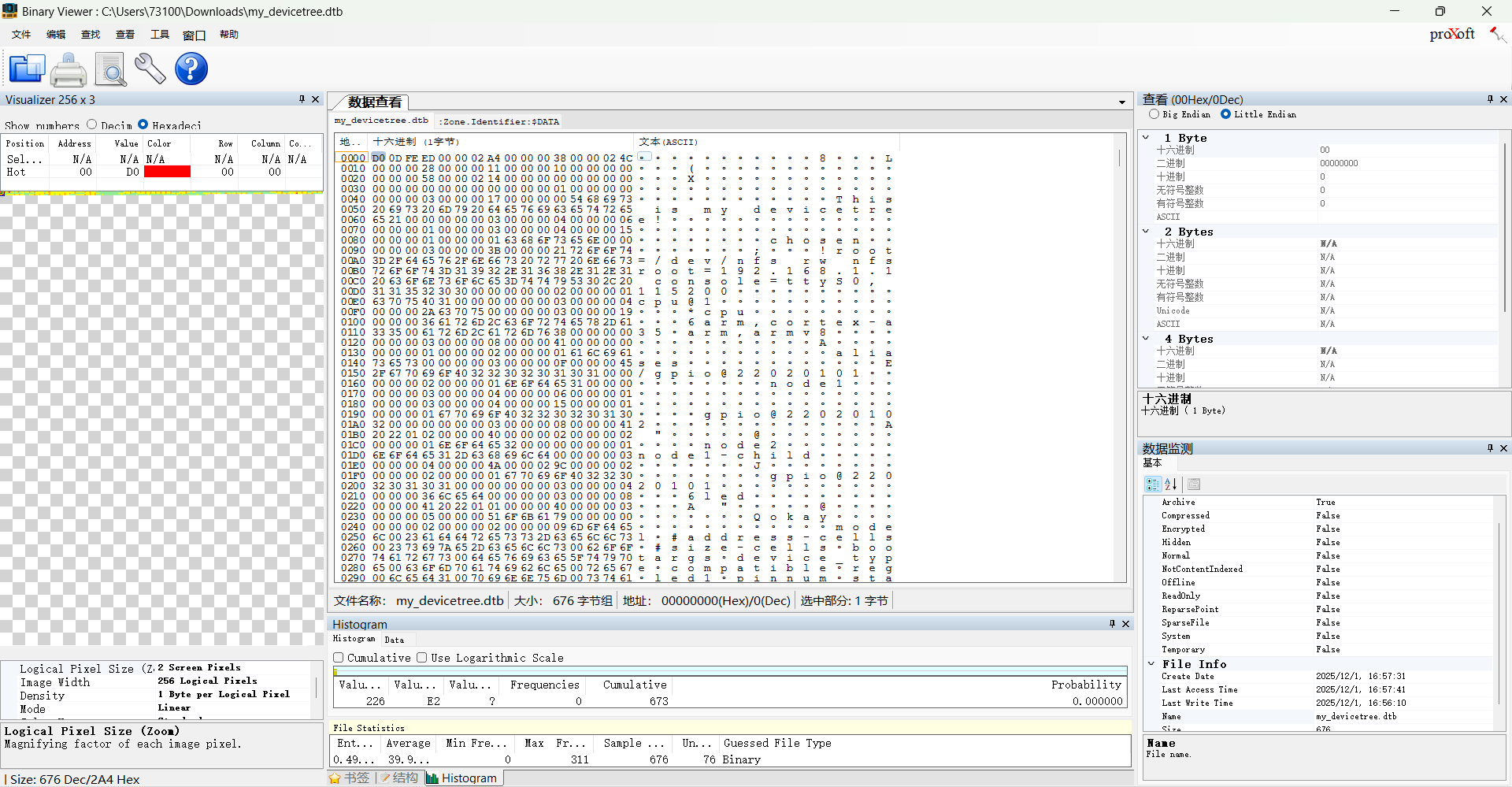
Header
123456789101112131415161718192021 | struct fdt_header { uint32_t magic; // Magic number of the device tree header uint32_t totalsize; // Total size of the device tree file uint32_t off_dt_struct; // Offset of the device tree structure (node data) relative to the beginning of the file uint32_t off_dt_strings; // Offset of the device tree strings table relative to the beginning of the file uint32_t off_mem_rsvmap; // Offset of the memory reservation map relative to the beginning of the file uint32_t version; // Device tree version number uint32_t last_comp_version; // Last compatible version number uint32_t boot_cpuid_phys; // Physical ID of the boot CPU uint32_t size_dt_strings; // Size of the device tree strings table uint32_t size_dt_struct; // Size of the device tree structure (node data)}; |
| Core Function Classification | field | Key Notes |
|---|---|---|
| File Identification | magic | Fixed magic number of DTB (0xd00dfeed, big-endian), used to verify file validity. |
| Size and Offset Positioning | totalsize | Total size of DTB (including all blocks and gaps), determines the file read range. |
off_dt_struct | Offset of the structure block (stores hardware nodes/attributes), the core entry point for parsing hardware descriptions. | |
off_dt_strings | Offset of the strings block (stores property names), used with indexes in the structure block to obtain property names. | |
off_mem_rsvmap | Offset of the memory reservation block (marks non-allocatable memory regions), to avoid kernel memory conflicts. | |
size_dt_strings | String block length, used to read the complete set of property names | |
size_dt_struct | Structure block length, used to read the complete hardware description data | |
| Version compatibility | version | The format version that the current DTB follows, which determines the parsing logic |
last_comp_version | The minimum backward-compatible version, ensuring compatibility across different kernel versions | |
| Hardware association | boot_cpuid_phys | Physical ID of the boot CPU, corresponding to the CPU node in the device treeregattribute, used for core identification in multi-core systems |
Memory Reserved Block
The Memory Reserved Block is a list of protected and reserved physical memory regions for client programs.
These reserved regions should not be used for general memory allocation, but rather to protect important data structures from being overwritten by client programs. 。
- Reserved region list: The Memory Reserved Block is a list consisting of a set of 64-bit big-endian integer pairs. Each pair of integers corresponds to a reserved memory region, containing the physical address and the size of the region (in bytes). These reserved regions should not overlap each other.
Each reserved region in the Memory Reserved Block is represented by a 64-bit big-endian integer pair. Each pair is represented by the following C structure
1234 | struct fdt_reserve_entry { uint64_t address; uint64_t size;}; |
The first integer represents the physical address of the reserved region, and the second integer represents the size of the reserved region (in bytes). Each integer is represented in 64-bit form, even on 32-bit architectures. On 32-bit CPUs, the upper 32 bits of the integer are ignored.
- Purpose of reserved regions: Client programs should not access the reserved regions in the Memory Reserved Block unless other information provided by the boot program explicitly indicates that access is allowed. The boot program may use specific methods to indicate that client programs can access parts of the reserved memory. The boot program may describe the specific uses of reserved memory in documentation, optional extensions, or platform-specific documentation.
The Memory Reserved Block provides the device tree with the ability to protect and reserve physical memory regions. It ensures that specific memory regions are not modified or used while client programs are running. This ensures that the boot program and other critical components can access specific parts of the reserved memory when needed, and protects critical data structures from accidental modification.
Structure Block
The Structure Block is the part of the device tree that describes the structure and content of the device tree itself. Itconsists of a series of token sequences with data, organized in a linear tree structure.。
Token types
The tokens in the structure block are divided into five types, each used for a different purpose.
FDT_BEGIN_NODE (0x00000001)
FDT_BEGIN_NODEMark Indicates the start of a node. . It is followed by the unit name of the node as additional data. The node name is stored as a null-terminated string, and may include the unit address. After the node name, it may be necessary to pad with zero bytes for alignment, followed by the next token, which can be except…FDT_ENDAny marks other than.
FDT_END_NODE (0x00000002)
FDT_END_NODEMark Indicates the end of a node . This marker has no additional data, immediately followed by the next marker, which can be anything exceptFDT_PROPAny marks other than.
FDT_PROP (0x00000003)
FDT_PROPMark Indicates the start of a property in the device tree. It is followed by additional data describing the attribute, which first consists of the attribute’s length and name, represented as the following C structure.
1234 | struct { uint32_t len; uint32_t nameoff;} |
Length indicates the byte length of the attribute value, and the name offset points to the location in the string block where the attribute name is stored.
After this structure, the value of the attribute is given as a byte string. After the attribute value, it may be necessary to pad with zero bytes for alignment, then the next token, which can be anything exceptFDT_ENDAny marks other than.
FDT_NOP (0x00000004)
FDT_NOPThe token can be ignored by programs that parse the device tree. This token has no additional data; it is immediately followed by the next token, which can be any valid token. UseFDT_NOPTokens can override attribute or node definitions in the tree, thereby removing them from the tree without moving other parts of the device tree blob.
tree structure
The structure of the device tree is represented in the form of a linear tree. Each node isFDT_BEGIN_NODEMark start, byFDT_END_NODEMark end.
The attributes and child nodes of the node are inFDT_END_NODEPreviously stated, therefore the child node’sFDT_BEGIN_NODEandFDT_END_NODEThe token is nested within the parent node’s token.
End of structure block
Structure block as a singleFDT_ENDEnd marker. This marker has no additional data; it is at the end of the structure block and is the last marker in the structure block.FDT_ENDThe bytes after the marker should be located at the offset of the start of the structure block, which is equal to the offset in the device tree blob header.size_dt_structThe value of the field.
String block
The string block is used to store all property names used in the device tree. It consists of a series of null-terminated strings that are simply concatenated together in the string block.
- String concatenation
Strings in the string blockConcatenated with a null character (\0) as the terminator. This means each string ends with a null character, and the next string immediately follows the end of the previous one. This concatenation method makes all strings in the string block form a continuous character sequence.
- Offset reference
In the structure block,the name of a property references the corresponding string in the string block by an offset. The offset is an unsigned integer value that represents the position of the string in the string block. By using offset references, the device tree can save space and become more flexible when property names change, because only the offset needs to be updated, without modifying the property references in the structure block.
- Alignment constraint
The string block has no alignment constraint, which means it can appear at any offset in the device tree blob. This makes the position of the string block flexible in the device tree blob and can be adjusted as needed without affecting the parsing and processing of the device tree.
The string block is the part of the device tree used to store property names. It is formed by concatenated strings and is referenced in the structure block by offsets. The flexible position of the string block makes the device tree representation more compact and extensible.
dtb expansion into device_node

- U-Boot loading
U-Boot (Universal Bootloader) is a commonly used open-source boot loader for booting embedded systems. During system startup, U-Boot willboot.imgload the kernel and device tree binary files into a specific address in system memory.
- Kernel initialization
After U-Boot loads the kernel and device tree binary files to a specific address in system memory, control is transferred to the kernel. During kernel initialization, the device tree binary file is parsed and expanded into a data structure that the kernel can recognize, so that the kernel can correctly initialize and manage hardware resources.
- Device tree expansion
Device tree expansion refers to the process of parsing the device tree binary file into device nodes in the kernel (device_nodestruct device_node). The kernel reads the contents of the device tree binary file and, based on the description information in the device tree, constructs device tree data structures, such as device nodes, interrupt controllers, registers, clocks, etc. These device tree data structures will be used to manage and configure hardware resources during kernel runtime.
struct device_nodedefined as follows
12345678910111213141516171819202122232425262728293031323334353637383940414243444546 | // include/linux/of.htypedef u32 phandle;typedef u32 ihandle;struct property { char *name; // Attribute name int length;// Attribute value length (bytes) void *value;// Attribute value pointer struct property *next;// Next attribute node pointer unsigned long _flags;// Attribute flags unsigned int unique_id;// Attribute unique identifier struct bin_attribute attr;// Kernel object binary attribute};struct of_irq_controller;struct device_node { const char *name; //Device node name phandle phandle; // Device node handle const char *full_name;// Device node full name struct fwnode_handle fwnode;// Device node firmware node handle struct property *properties;// Device node attribute list struct property *deadprops; /* removed properties */ // Deleted attribute list struct device_node *parent; // Parent device node pointer struct device_node *child; // Child device node pointer struct device_node *sibling; // Sibling device node pointer struct kobject kobj; // Kernel object (for sysfs) unsigned long _flags; // Device node flags void *data; // Device node related data pointer unsigned int unique_id;// Device node unique identifier struct of_irq_controller *irq_trans;// Device node interrupt controller}; |
Source code analysis of the DTB parsing process
init/main.c
In the kernelstart_kernel()call insetup_arch(&command_line);Perform architecture-specific initialization
12345678910111213141516171819202122232425262728293031323334 | // init/main.casmlinkage __visible void __init __no_sanitize_address start_kernel(void){ char *command_line; char *after_dashes; set_task_stack_end_magic(&init_task);// Set the task stack magic number smp_setup_processor_id();// Set processor ID debug_objects_early_init();// Initialize debug objects cgroup_init_early();// Initialize cgroup (control group) local_irq_disable();// Disable local interrupts early_boot_irqs_disabled = true;// Mark interrupts as disabled during early boot /* * Interrupts are still disabled。Perform necessary setup,Then enable them。 */ boot_cpu_init();// Initialize boot CPU page_address_init();// Set up page address pr_notice("%s", linux_banner);// Print Linux kernel version information early_security_init(); setup_arch(&command_line);// Architecture-specific initialization setup_boot_config(command_line); setup_command_line(command_line);// Set up command line parameters setup_nr_cpu_ids();// Set number of CPUs setup_per_cpu_areas();// Set up per-CPU areas smp_prepare_boot_cpu(); /* arch-specific boot-cpu hooks */ boot_cpu_hotplug_init();// Initialize the hotplug boot CPU build_all_zonelists(NULL);// Build all memory zone lists page_alloc_init();// Initialize the page allocator ...} |
arch/arm64/kernel/setup.c
And in thesetup_arch()Called at line 21 belowsetup_machine_fdt(__fdt_pointer);Set up the machine’s FDT (platform device tree)
1234567891011121314151617181920212223242526272829303132333435363738394041424344454647484950515253545556575859606162636465 | // arch/arm64/kernel/setup.cvoid __init __no_sanitize_address setup_arch(char **cmdline_p){ init_mm.start_code = (unsigned long) _text; init_mm.end_code = (unsigned long) _etext; init_mm.end_data = (unsigned long) _edata; init_mm.brk = (unsigned long) _end; *cmdline_p = boot_command_line; /* * If know now we are going to need KPTI then use non-global * mappings from the start, avoiding the cost of rewriting * everything later. */ arm64_use_ng_mappings = kaslr_requires_kpti(); early_fixmap_init();// Initialize early fixmap early_ioremap_init();// Initialize early ioremap setup_machine_fdt(__fdt_pointer);// Set up the machine's FDT (platform device tree) /* * Initialise the static keys early as they may be enabled by the * cpufeature code and early parameters. */ jump_label_init();// Initialize static keys, which may be enabled early by cpufeature code and early parameters parse_early_param(); /* * Unmask asynchronous aborts and fiq after bringing up possible * earlycon. (Report possible System Errors once we can report this * occurred). */ // After starting the possible early console, unmask asynchronous interrupts and FIQ (we can immediately report system errors that occur) local_daif_restore(DAIF_PROCCTX_NOIRQ); /* * TTBR0 is only used for the identity mapping at this stage. Make it * point to zero page to avoid speculatively fetching new entries. */ cpu_uninstall_idmap();// At this stage, TTBR0 is only used for identity mapping. Point it to the zero page to avoid speculative new entry fetches. xen_early_init();// Early initialization of the Xen platform efi_init();// EFI platform initialization if (!efi_enabled(EFI_BOOT) && ((u64)_text % MIN_KIMG_ALIGN) != 0) pr_warn(FW_BUG "Kernel image misaligned at boot, please fix your bootloader!"); arm64_memblock_init();// ARM64 memory block initialization paging_init();// Paging initialization acpi_table_upgrade();// ACPI table upgrade /* Parse the ACPI tables for possible boot-time configuration */ acpi_boot_table_init();// Parse ACPI tables for possible boot-time configuration if (acpi_disabled) unflatten_device_tree();// Unflatten device tree bootmem_init();// Boot memory initialization ...} |
setup_machine_fdt(__fdt_pointer)
__fdt_pointerIt is the address where the dtb binary is loaded into memory, passed by the bootloader to the kernel via the x0 register
arch/arm64/kernel/head.S
123456789 | // arch/arm64/kernel/head.SSYM_CODE_START_LOCAL(preserve_boot_args) mov x21, x0 // x21=FDT ...SYM_FUNC_START_LOCAL(__primary_switched) ... str_l x21, __fdt_pointer, x5 // Save FDT pointer ... |
arch/arm64/kernel/setup.c
12345678910111213141516171819202122232425262728293031323334 | // arch/arm64/kernel/setup.c// Initialize the device tree that sets up the machinestatic void __init setup_machine_fdt(phys_addr_t dt_phys){ int size; // Map the device tree physical address to the kernel virtual address space void *dt_virt = fixmap_remap_fdt(dt_phys, &size, PAGE_KERNEL); const char *name; if (dt_virt)// If the mapping succeeds memblock_reserve(dt_phys, size);// Reserve the memory region occupied by the device tree if (!dt_virt || !early_init_dt_scan(dt_virt)) {// If the device tree mapping fails or the device tree parsing fails pr_crit("\n" "Error: invalid device tree blob at physical address %pa (virtual address 0x%p)\n" "The dtb must be 8-byte aligned and must not exceed 2 MB in size\n" "\nPlease check your bootloader.", &dt_phys, dt_virt); while (true)// Infinite loop, waiting for the system to crash cpu_relax(); } /* Early fixups are done, map the FDT as read-only now */ fixmap_remap_fdt(dt_phys, &size, PAGE_KERNEL_RO);// Map the device tree as read-only name = of_flat_dt_get_machine_name();// Get the machine name from the device tree if (!name) return; pr_info("Machine model: %s\n", name);// Output the machine model information dump_stack_set_arch_desc("%s (DT)", name);// Set the architecture description for stack dump to the machine model} |
Line 13 aboveearly_init_dt_scanThe function performs compatibility and integrity validation on the device tree. It may check the consistency markers, version information, and the presence of required nodes and properties in the device tree. If validation fails, the function returns false. The function is as follows:
12345678910111213 | // drivers/of/fdt.cbool __init early_init_dt_scan(void *params){ bool status; status = early_init_dt_verify(params);// Validate the compatibility and integrity of the device tree if (!status) return false; early_init_dt_scan_nodes();// scan device tree nodes return true;} |
early_init_dt_scanFirst, it callsearly_init_dt_verifyValidate the device tree to verify its compatibility and integrity
1234567891011121314151617181920 | // drivers/of/fdt.cbool __init early_init_dt_verify(void *params){ if (!params)// Verify whether the passed-in parameter is empty. return false; /* check device tree validity */ // Check the validity of the device tree header. // If the device tree header is invalid, return false. if (fdt_check_header(params)) return false; /* Setup flat device-tree pointer */ initial_boot_params = params;// Set the pointer to the device tree to the passed-in parameter. // Calculate the CRC32 checksum of the device tree. // and store the result in the global variable of_fdt_crc32 of_fdt_crc32 = crc32_be(~0, initial_boot_params, fdt_totalsize(initial_boot_params)); return true;} |
Finally,early_init_dt_scancallsearly_init_dt_scan_nodesscan device tree nodes
12345678910111213141516 | // drivers/of/fdt.cvoid __init early_init_dt_scan_nodes(void){ int rc = 0; /* Retrieve various information from the /chosen node */ rc = of_scan_flat_dt(early_init_dt_scan_chosen, boot_command_line);/* retrieve various information from the /chosen node. */ if (!rc) pr_warn("No chosen node found, continuing without\n"); /* Initialize {size,address}-cells info */ of_scan_flat_dt(early_init_dt_scan_root, NULL);/* initialize {size,address}-cells information. */ /* Setup memory, calling early_init_dt_add_memory_arch */ of_scan_flat_dt(early_init_dt_scan_memory, NULL);/* set memory information, call early_init_dt_add_memory_arch function */} |
functionearly_init_dt_scan_nodesis declared as__init, whichindicates that it is called during the kernel initialization phase.,and is no longer needed after initialization is complete.. The purpose of this function is to scan device tree nodes in the early stage and perform some initialization operations.
The function mainly callsof_scan_flat_dtfunction, which is used to scan the flat device tree. The flat device tree is a
unflatten_device_tree()
This function is used to parse the device tree, converting the compact device tree data structure into a tree-structured device tree.
1234567891011121314 | // drivers/of/fdt.cvoid __init unflatten_device_tree(void){ /* Parse the device tree */ __unflatten_device_tree(initial_boot_params, NULL, &of_root, early_init_dt_alloc_memory_arch, false); /* Get pointer to "/chosen" and "/aliases" nodes for use everywhere */ /* Get pointers to the "/chosen" and "/aliases" nodes for global use. */ of_alias_scan(early_init_dt_alloc_memory_arch); /* Run unit tests for the device tree */ unittest_unflatten_overlay_base();} |
This function is mainly used to parse the device tree and store the parsed device tree in a global variable.of_rootMiddle.
The function first calls__unflatten_device_treefunction to perform the device tree parsing operation. The parsed device tree will be stored usingof_rootpointer.
Next, the function callsof_alias_scanfunction. This function is used to scan the/chosenand/aliasesnodes in the device tree, and allocate memory for them. In this way, other parts of the code can access these nodes through global variables.
Finally, the function callsunittest_unflatten_overlay_basefunction to run unit tests for the device tree.
__unflatten_device_tree
123456789101112131415161718192021222324252627282930313233343536373839404142434445464748495051525354555657585960616263646566676869707172737475767778 | //drivers/of/fdt.c/** * __unflatten_device_tree - create tree of device_nodes from flat blob * * unflattens a device-tree, creating the * tree of struct device_node. It also fills the "name" and "type" * pointers of the nodes so the normal device-tree walking functions * can be used. * @blob: The blob to expand * @dad: Parent device node * @mynodes: The device_node tree created by the call * @dt_alloc: An allocator that provides a virtual address to memory * for the resulting tree * @detached: if true set OF_DETACHED on @mynodes * * Returns NULL on failure or the memory chunk containing the unflattened * device tree on success. */void *__unflatten_device_tree(const void *blob, struct device_node *dad, struct device_node **mynodes, void *(*dt_alloc)(u64 size, u64 align), bool detached){ int size; void *mem; pr_debug(" -> unflatten_device_tree()\n"); if (!blob) { pr_debug("No device tree pointer\n"); return NULL; } pr_debug("Unflattening device tree:\n"); pr_debug("magic: %08x\n", fdt_magic(blob)); pr_debug("size: %08x\n", fdt_totalsize(blob)); pr_debug("version: %08x\n", fdt_version(blob)); if (fdt_check_header(blob)) { pr_err("Invalid device tree blob header\n"); return NULL; } /* First pass, scan for size */ size = unflatten_dt_nodes(blob, NULL, dad, NULL);/* First pass scan, calculate size */ if (size < 0) return NULL; size = ALIGN(size, 4); pr_debug(" size is %d, allocating...\n", size); /* Allocate memory for the expanded device tree */ mem = dt_alloc(size + 4, __alignof__(struct device_node));/* Allocate memory for the expanded device tree */ if (!mem) return NULL; memset(mem, 0, size); *(__be32 *)(mem + size) = cpu_to_be32(0xdeadbeef); pr_debug(" unflattening %p...\n", mem); /* Second pass, do actual unflattening */ unflatten_dt_nodes(blob, mem, dad, mynodes);/* Second pass scan, actually expand the device tree */ if (be32_to_cpup(mem + size) != 0xdeadbeef) pr_warn("End of tree marker overwritten: %08x\n", be32_to_cpup(mem + size)); if (detached && mynodes) { of_node_set_flag(*mynodes, OF_DETACHED); pr_debug("unflattened tree is detached\n"); } pr_debug(" <- unflatten_device_tree()\n"); return mem;} |
The focus of this function is on two scans of the device tree. The purpose of the first scan is to calculate the memory size required to expand the device tree.
Line 46:size = unflatten_dt_nodes(blob, NULL, dad, NULL);The function recursively traverses the device tree data block and calculates the memory size required to expand the device tree. It accepts four parameters:
- blob (device tree data block pointer)
- start (starting address of the current node, initially NULL)
- dad (parent node pointer, and
unflatten_device_treeNULL is passed in the function) - mynodes (pointer to an array of node pointers, initially NULL).
After the first scan is completed,unflatten_dt_nodesThe function will
Line 65: called againunflatten_dt_nodes(blob, mem, dad, mynodes);The function performs a second pass. Through this process,
unflatten_dt_nodes()
1234567891011121314151617181920212223242526272829303132333435363738394041424344454647484950515253545556575859606162636465666768697071727374757677787980 | // drivers/of/fdt.c/** * unflatten_dt_nodes - Alloc and populate a device_node from the flat tree * @blob: The parent device tree blob * @mem: Memory chunk to use for allocating device nodes and properties * @dad: Parent struct device_node * @nodepp: The device_node tree created by the call * * It returns the size of unflattened device tree or error code */static int unflatten_dt_nodes(const void *blob, void *mem, struct device_node *dad, struct device_node **nodepp){ struct device_node *root;// root node int offset = 0, depth = 0, initial_depth = 0;// offset, depth, and initial depth struct device_node *nps[FDT_MAX_DEPTH];// device node array void *base = mem;// base address, used to calculate offsets bool dryrun = !base;// whether it is only a simulated run without actual processing if (nodepp) *nodepp = NULL;// If the pointer is not null, set it to a null pointer /* * We're unflattening device sub-tree if @dad is valid. There are * possibly multiple nodes in the first level of depth. We need * set @depth to 1 to make fdt_next_node() happy as it bails * immediately when negative @depth is found. Otherwise, the device * nodes except the first one won't be unflattened successfully. */ /* * if @dad valid,it indicates that the device subtree is being unflattened。 * At the first depth level, there may be multiple nodes。 * will @depth Set to 1,so that fdt_next_node() works properly。 * When a negative value is found @depth when,the function will exit immediately。 * otherwise,Device nodes other than the first node will not be unflattened successfully。 */ if (dad) depth = initial_depth = 1; root = dad;// The root node is @dad nps[depth] = dad;// Add the root node to the device node array for (offset = 0; offset >= 0 && depth >= initial_depth; offset = fdt_next_node(blob, offset, &depth)) { if (WARN_ON_ONCE(depth >= FDT_MAX_DEPTH - 1)) continue; // If CONFIG is not enabled_OF_KOBJ and the node is unavailable, then skip the node if (!IS_ENABLED(CONFIG_OF_KOBJ) && !of_fdt_device_is_available(blob, offset)) continue; // Fill in node information and add child nodes to the device node array if (!populate_node(blob, offset, &mem, nps[depth], &nps[depth+1], dryrun)) return mem - base; if (!dryrun && nodepp && !*nodepp) *nodepp = nps[depth+1];// Assign the child node pointer to @nodepp if (!dryrun && !root) root = nps[depth+1];// If the root node is NULL, set the child node as the root node } if (offset < 0 && offset != -FDT_ERR_NOTFOUND) { pr_err("Error %d processing FDT\n", offset); return -EINVAL; } /* * Reverse the child list. Some drivers assumes node order matches .dts * node order */ if (!dryrun)// Reverse the child node list. Some drivers assume the node order matches the order in the .dts file reverse_nodes(root); return mem - base;// Return the number of bytes processed} |
fdt_next_node()The function is used to traverse the nodes of the device tree.
Starting from offset 0, as long as the offset is greater than or equal to 0 and the depth is greater than or equal to the initial depth, execute the loop.
Each iteration of the loop processes one device tree node. In each iteration, first check whether the depth exceeds the maximum depthFDT_MAX_DEPTHIf it exceeds, skip the node.
If not enabledCONFIG_OF_KOBJand the node is unavailable (viaof_fdt_device_is_available()function), then skip the node.
Then callpopulate_node()the function to fill in node information and add child nodes to the device node arraynpsMiddle.populate_node()The function definition is as follows
populate_node
This function parses the device node’s properties and allocates memory as needed to store the property values.
1234567891011121314151617181920212223242526272829303132333435363738394041424344454647 | // drivers/of/fdt.cstatic bool populate_node(const void *blob, int offset, void **mem, struct device_node *dad, struct device_node **pnp, bool dryrun){ struct device_node *np;// Device node pointer const char *pathp;// Node path string pointer unsigned int l, allocl;// Path string length and allocated memory size pathp = fdt_get_name(blob, offset, &l);// Get the node path and length if (!pathp) { *pnp = NULL; return false; } allocl = ++l;// Allocate memory of size path length plus one to store the node path string np = unflatten_dt_alloc(mem, sizeof(struct device_node) + allocl, __alignof__(struct device_node));// Allocate device node memory if (!dryrun) { char *fn; of_node_init(np);// Initialize device node np->full_name = fn = ((char *)np) + sizeof(*np);// Set the full path name of the device node memcpy(fn, pathp, l);// Copy the node path string into the full path name of the device node if (dad != NULL) { np->parent = dad;// Set the parent node of the device node np->sibling = dad->child;// Set the sibling node of the device node dad->child = np;// Add the device node as a child of the parent node } } populate_properties(blob, offset, mem, np, pathp, dryrun);// Fill in the attribute information of the device node if (!dryrun) { np->name = of_get_property(np, "name", NULL);// Get the name attribute of the device node if (!np->name) np->name = "<NULL>"; } *pnp = np;// Assign the device node pointer to *pnp return true;} |
Beforepopulate_nodeIn the function, it first callsunflatten_dt_allocThe function allocates memory for the device node.
The allocated memory size issizeof(struct device_node) + alloclbytes, and use__alignof__(struct device_node)alignment, then callpopulate_propertiesThe function fills in the attribute information of the device node.
Here
np->name = of_get_property(np, "name", NULL);Get the name attribute of the device node stored instruct device_nodeofnamein the attribute
device_node to platform_device
In the platform bus model, the device part is described usingplatform_devicea structure to describe hardware resources, so the kernel will ultimately convert the kernel-recognizeddevice_nodetree conversionplatform_device, but
Not all device_node will be converted to platform_device
Only those that meet the requirements will be converted toplatform_device, converted toplatform_deviceThe node can be/sys/bus/platform/devicesviewed below.
Conversion rules
The rules are as follows:
- Traverse the child nodes under the root node that contain the compatible property, and for each child node, create a corresponding
platform_device。 - Traverse the nodes under the root node whose compatible property is
simple-bus、simple-mfdorisanodes and their child nodes. If their child nodes contain a compatible property value, a correspondingplatform_device。 - Check whether the node’s compatible property contains
armorprimecell. If so, do not convert the node toplatform_device, but instead identify it as an AMBA device.
For rule 2:
Some nodes are themselves “bus” or “container” but do not directly correspond to hardware devices; instead, they are used to organize child devices. The compatible values of these nodes are usually:
simple-bus: generic simple bus (e.g., an ordinary memory-mapped bus outside AMBA APB/AHB)simple-mfd: multi-function device (Multi-Function Device) containerisa: ISA bus (legacy PC)
For such nodes, they themselves usually do not createplatform_device, but will recursively traverse all their child nodes; as long as a child node has a compatible property, create one for that child nodeplatform_device
Purpose: to support the “bus nesting” structure in the device tree. For example, peripherals inside an SoC are attached under a simple-bus node.
For rule 3:
If a node’s compatible string containsarm,xxxorprimecell(such asarm,pl011、arm,pl081), it indicates that it is an ARM PrimeCell peripheral, belonging to an AMBA bus device (APB/AHB). Such devices:
- will not be registered as
platform_device, but instead by the AMBA bus subsystem (amba_bus_type) specially handled - use
amba_devicestructure, rather thanplatform_device
Reason: ARM PrimeCell devices have a standard register layout (such as CID/PID), and the AMBA subsystem automatically detects and verifies them, compared to genericplatform_devicemore secure and efficient.
example
Example 1:
123456789101112131415161718192021222324252627282930313233343536373839 | /dts-v1/;/ { model = "This is my devicetree!"; chosen { bootargs = "root=/dev/nfs rw nfsroot=192.168.1.1 console=ttyS0,115200"; }; cpu1: cpu@1 { device_type = "cpu"; compatible = "arm,cortex-a35", "arm,armv8"; reg = <0x0 0x1>; }; aliases { led1 = "/gpio@22020101"; }; node1 { gpio@22020102 { reg = <0x20220102 0x40>; }; }; node2 { node1-child { pinnum = <01234>; }; }; gpio@22020101 { compatible = "led"; reg = <0x20220101 0x40>; status = "okay"; };} |
In the device tree above, there arechosen、cpu1: cpu@1、aliases、node1、node2、gpio@22020101these six nodes. Among them, the first five nodes do not have a compatible property, so they will not be converted toplatform_device, and the last onegpio@22020101node conforms to Rule 1, is under the root node, and has a compatible property, so it will eventually be converted toplatform_device。
Example 2:
1234567891011121314151617181920212223242526272829303132333435363738394041 | /dts-v1/;/ { model = "This is my devicetree!"; chosen { bootargs = "root=/dev/nfs rw nfsroot=192.168.1.1 console=ttyS0,115200"; }; cpu1: cpu@1 { device_type = "cpu"; compatible = "arm,cortex-a35", "arm,armv8"; reg = <0x0 0x1>; }; aliases { led1 = "/gpio@22020101"; }; node1 { compatible = "simple-bus"; gpio@22020102 { reg = <0x20220102 0x40>; }; }; node2 { node1-child { pinnum = <01234>; }; }; gpio@22020101 { compatible = "led"; reg = <0x20220101 0x40>; status = "okay"; };}; |
Here, in thenode1node, a compatible property is added, but the value of this compatible property issimple-bus, we need to continue looking at its child nodes. The child nodegpio@22020102does not have a compatible property value, so thenode1node will not be converted.
Example 3:
12345678910111213141516171819202122232425262728293031323334353637383940414243 | /dts-v1/;/ { model = "This is my devicetree!"; chosen { bootargs = "root=/dev/nfs rw nfsroot=192.168.1.1 console=ttyS0,115200"; }; cpu1: cpu@1 { device_type = "cpu"; compatible = "arm,cortex-a35", "arm,armv8"; reg = <0x0 0x1>; }; aliases { led1 = "/gpio@22020101"; }; node1 { compatible = "simple-bus"; gpio@22020102 { compatible = "gpio"; reg = <0x20220102 0x40>; }; }; node2 { node1-child { pinnum = <01234>; }; }; gpio@22020101 { compatible = "led"; reg = <0x20220101 0x40>; status = "okay"; };}; |
Here, in the child node of node1gpio@22020102a compatible property is added. The compatible property value of node1 issimple-bus, then we need to continue looking at its child nodes. The child nodegpio@22020102has a compatible property value of gpio, so thegpio@22020102node will be converted toplatform_device
Example 4:
12345678910111213141516171819202122232425262728293031323334353637383940414243444546 | /dts-v1/;/ { model = "This is my devicetree!"; chosen { bootargs = "root=/dev/nfs rw nfsroot=192.168.1.1 console=ttyS0,115200"; }; cpul: cpu@1 { device_type = "cpu"; compatible = "arm,cortex-a35", "arm,armv8"; reg = <0x0 0x1>; amba { compatible = "simple-bus"; ranges; dmac_peri: dma-controller@ff250000 { compatible = "arm,p1330", "arm,primecell"; reg = <0x0 0xff250000 0x0 0x4000>; interrupts = <GIC_SPI 2 IRQ_TYPE_LEVEL_HIGH>, <GIC_SPI 3 IRQ_TYPE_LEVEL_HIGH>; arm,pl330-broken-no-flushp; arm,p1330-periph-burst; clocks = <&cru ACLK DMAC_PERI>; clock-names = "apb_pclk"; }; dmac_bus: dma-controller@ff600000 { compatible = "arm,p1330", "arm,primecell"; reg = <0x0 0xff600000 0x0 0x4000>; interrupts = <GIC_SPI 0 IRQ_TYPE_LEVEL_HIGH>, <GIC_SPI 1 IRQ_TYPE_LEVEL_HIGH>; arm,pl330-broken-no-flushp; arm,pl330-periph-burst; clocks = <&cru ACLK_DMAC_BUS>; clock-names = "apb_pclk"; }; }; };}; |
The compatible value of the amba node issimple-bus, so it will not be converted toplatform_device, but instead serves as a parent node to organize other devices, so we need to look at its child nodes.
dmac_peri: dma-controller@ff250000Node: The compatible property of this node containsarm,p1330andarm,primecell, according to rule 3, this node will not be converted toplatform_device, but is recognized as an AMBA device.
dmac_bus: dma-controller@ff600000Node: The compatible property of this node containsarm,p1330andarm,primecell, according to rule 3, this node will not be converted toplatform_device, but is recognized as an AMBA device.
Source code analysis
of_platform_default_populate_init()
Let’s first look atof_platform_default_populate_init, it usesarch_initcall_sync(of_platform_default_populate_init);registers the function to be called during the startup phase
123456789101112131415161718192021222324252627282930313233343536 | // drivers/of/platform.cstatic int __init of_platform_default_populate_init(void){ struct device_node *node; // Suspend device link supplier synchronization state device_links_supplier_sync_state_pause(); // If the device tree has not been populated, return an error code. if (!of_have_populated_dt()) return -ENODEV; /* * Handle certain compatibles explicitly, since we don't want to create * platform_devices for every node in /reserved-memory with a * "compatible", */ /* * Explicitly handle certaincompatibles,Because we don't want to/reserved-memory each in ... that has“compatible”create a nodeplatform_device。 */ for_each_matching_node(node, reserved_mem_matches) of_platform_device_create(node, NULL, NULL); // Find the node "/firmware" node = of_find_node_by_path("/firmware"); if (node) { // Use this node to populate device tree platform devices. of_platform_populate(node, NULL, NULL, NULL); of_node_put(node); } /* Populate everything else. */ of_platform_default_populate(NULL, NULL, NULL);// populate other devices return 0;}arch_initcall_sync(of_platform_default_populate_init); |
arch_initcall_syncis a function in the Linux kernel that is used to execute architecture-specific initialization functions during kernel initialization. It belongs to the kernel’s initialization call mechanism and is used to ensure that initialization functions specific to a particular architecture are called in a timely manner during system startup.
During the Linux kernel initialization process, various subsystems and architectures register their own initialization functions. These initialization functions are responsible for completing initialization work specific to a subsystem or architecture, such as initializing hardware devices, registering interrupt handlers, setting up memory mappings, etc. And arch_initcall_syncThe function is used to call initialization functions related to the current architecture.
When the kernel starts, callrest_init()function to start the initialization process. During the initialization process,arch_initcall_syncThe function will be called to ensure that all initialization functions related to the current architecture are executed in the correct order. This guarantees that architecture-specific initialization work is completed correctly during the startup process.
And of_platform_default_populate_initThe function’s role is to automatically parse the device tree during kernel initialization.,and creates corresponding based on the device nodes in the device treeplatform_devicestructure. It will traverse the device nodes in the device tree, and for each device node create a correspondingplatform_devicestructure, and then register it with the kernel, so that device drivers can recognize and operate these devices.
of_platform_default_populate_initThe function ultimately callsof_platform_default_populatepopulate other devices
12345678 | // drivers/of/platform.cint of_platform_default_populate(struct device_node *root, const struct of_dev_auxdata *lookup, struct device *parent){ return of_platform_populate(root, of_default_bus_match_table, lookup, parent);} |
The function is used to callof_platform_populatefunction to populate the platform devices in the device tree, and use the default device matching tableof_default_bus_match_table, the device matching table is as follows:
12345678910 | // drivers/of/platform.cconst struct of_device_id of_default_bus_match_table[] = { { .compatible = "simple-bus", }, { .compatible = "simple-mfd", }, { .compatible = "isa", }, { .compatible = "arm,amba-bus", }, {} /* Empty terminated list */}; |
The above device matching table is the second rule:
Traverse the nodes under the root node that contain compatible attribute is simple-bus、simple-mfd or isa the nodes and their child nodes。If their child nodes contain compatible attribute value
The function will automatically match the corresponding device driver based on the attributes of the device tree node, and populate the kernel’s platform device list.
of_platform_populate()
of_platform_populateThe function is defined as follows:
1234567891011121314151617181920212223242526272829303132333435363738394041424344454647484950515253545556 | // drivers/of/platform.c/** * of_platform_populate() - Populate platform_devices from device tree data * @root: parent of the first level to probe or NULL for the root of the tree * @matches: match table, NULL to use the default * @lookup: auxdata table for matching id and platform_data with device nodes * @parent: parent to hook devices from, NULL for toplevel * * Similar to of_platform_bus_probe(), this function walks the device tree * and creates devices from nodes. It differs in that it follows the modern * convention of requiring all device nodes to have a 'compatible' property, * and it is suitable for creating devices which are children of the root * node (of_platform_bus_probe will only create children of the root which * are selected by the @matches argument). * * New board support should be using this function instead of * of_platform_bus_probe(). * * Returns 0 on success, < 0 on failure. */int of_platform_populate(struct device_node *root, const struct of_device_id *matches, const struct of_dev_auxdata *lookup, struct device *parent){ struct device_node *child; int rc = 0; // If root is not NULL, increment the reference count of the root node; otherwise, look up the root node in the device tree by path. root = root ? of_node_get(root) : of_find_node_by_path("/"); if (!root) return -EINVAL; pr_debug("%s()\n", __func__); pr_debug(" starting at: %pOF\n", root); // Suspend device link supplier synchronization state device_links_supplier_sync_state_pause(); // Traverse all child nodes of the root node for_each_child_of_node(root, child) { // Create platform devices and add them to the device tree bus rc = of_platform_bus_create(child, matches, lookup, parent, true); if (rc) { of_node_put(child); break; } } // Resume device link supplier synchronization state device_links_supplier_sync_state_resume(); // Set the OF_POPULATED_BUS flag of_node_set_flag(root, OF_POPULATED_BUS); // Release the reference count of the root node of_node_put(root); return rc;}EXPORT_SYMBOL_GPL(of_platform_populate); |
of_platform_populateby callingrc = of_platform_bus_create(child, matches, lookup, parent, true);Createplatform_device。
of_platform_bus_create()
of_platform_bus_createdefined as follows:
123456789101112131415161718192021222324252627282930313233343536373839404142434445464748495051525354555657585960616263646566676869707172737475767778 | // drivers/of/platform.c/** * of_platform_bus_create() - Create a device for a node and its children. * @bus: device node of the bus to instantiate * @matches: match table for bus nodes * @lookup: auxdata table for matching id and platform_data with device nodes * @parent: parent for new device, or NULL for top level. * @strict: require compatible property * * Creates a platform_device for the provided device_node, and optionally * recursively create devices for all the child nodes. */static int of_platform_bus_create(struct device_node *bus, const struct of_device_id *matches, const struct of_dev_auxdata *lookup, struct device *parent, bool strict){ const struct of_dev_auxdata *auxdata; struct device_node *child; struct platform_device *dev; const char *bus_id = NULL; void *platform_data = NULL; int rc = 0; /* Make sure it has a compatible property */ /* Ensure the device node has a compatible property */ if (strict && (!of_get_property(bus, "compatible", NULL))) { pr_debug("%s() - skipping %pOF, no compatible prop\n", __func__, bus); return 0; } /* Skip nodes for which we don't want to create devices */ /* Skip nodes for which device creation is not desired */ if (unlikely(of_match_node(of_skipped_node_table, bus))) { pr_debug("%s() - skipping %pOF node\n", __func__, bus); return 0; } if (of_node_check_flag(bus, OF_POPULATED_BUS)) { pr_debug("%s() - skipping %pOF, already populated\n", __func__, bus); return 0; } auxdata = of_dev_lookup(lookup, bus); if (auxdata) { bus_id = auxdata->name; platform_data = auxdata->platform_data; } if (of_device_is_compatible(bus, "arm,primecell")) { /* * Don't return an error here to keep compatibility with older * device tree files. */ /* * Do not return an error here to maintain compatibility with old device tree files.。 */ of_amba_device_create(bus, bus_id, platform_data, parent); return 0; } dev = of_platform_device_create_pdata(bus, bus_id, platform_data, parent); if (!dev || !of_match_node(matches, bus)) return 0; for_each_child_of_node(bus, child) { pr_debug(" create child: %pOF\n", child); rc = of_platform_bus_create(child, matches, lookup, &dev->dev, strict); if (rc) { of_node_put(child); break; } } of_node_set_flag(bus, OF_POPULATED_BUS); return rc;} |
of_platform_bus_createby callingof_match_node(of_skipped_node_table, bus)Match the nodes that you want to skip,of_skipped_node_tabledefined as follows
1234 | static const struct of_device_id of_skipped_node_table[] = { { .compatible = "operating-points-v2", }, {} /* Empty terminated list */}; |
operating-points-v2
This is a Device Tree Binding used to describe the Operating Performance Points (OPP) of a CPU or device, such as different frequency/voltage combinations. It is not a hardware device, but a data table (describing performance states) that usually appears as a child node under CPU, GPU, or SoC device nodes.
123456789101112131415 | cpu@0 { compatible = "arm,cortex-a53"; ... operating-points-v2 { compatible = "operating-points-v2"; opp00 { opp-hz = /bits/ 64 <1000000000>; opp-microvolt = <900000>; }; opp01 { opp-hz = /bits/ 64 <1500000000>; opp-microvolt = <1000000>; }; };}; |
Thenof_platform_bus_createCallof_platform_device_create_pdataThe function creates a platform device and assigns it to the variable dev. Then, it checks whether the device node bus matches the given match tablematchesIf the platform device creation fails or the device node does not match, return 0.
Finally,of_platform_bus_createusefor_each_child_of_node(bus, child), traverse each child node child of the device node bus, and recursively callof_platform_bus_createthe function to create platform devices for the child nodes.
of_platform_device_create_pdata()
of_platform_device_create_pdatadefined as follows
123456789101112131415161718192021222324252627282930313233343536373839404142434445464748 | // drivers/of/platform.c/** * of_platform_device_create_pdata - Alloc, initialize and register an of_device * @np: pointer to node to create device for * @bus_id: name to assign device * @platform_data: pointer to populate platform_data pointer with * @parent: Linux device model parent device. * * Returns pointer to created platform device, or NULL if a device was not * registered. Unavailable devices will not get registered. */static struct platform_device *of_platform_device_create_pdata( struct device_node *np, const char *bus_id, void *platform_data, struct device *parent){ struct platform_device *dev; /* Check whether the device node is available or already populated. */ if (!of_device_is_available(np) || of_node_test_and_set_flag(np, OF_POPULATED)) return NULL; /* Allocate platform device structure */ dev = of_device_alloc(np, bus_id, parent); if (!dev) goto err_clear_flag; /* Set some properties of the platform device. */ dev->dev.coherent_dma_mask = DMA_BIT_MASK(32); if (!dev->dev.dma_mask) dev->dev.dma_mask = &dev->dev.coherent_dma_mask; dev->dev.bus = &platform_bus_type; dev->dev.platform_data = platform_data; of_msi_configure(&dev->dev, dev->dev.of_node); /* Add platform device to device model */ if (of_device_add(dev) != 0) { platform_device_put(dev); goto err_clear_flag; } return dev;err_clear_flag: of_node_clear_flag(np, OF_POPULATED);/* Clear the filled flag of the device node */ return NULL;} |
of_platform_device_create_pdataFunction callof_device_allocallocates a platform device structure, and passes the device node pointer, device identifier, and parent device pointer to it. If allocation fails, jump toerr_clear_flagPerform error handling at the label.
Lines 29 to 34of_platform_device_create_pdataSet some properties of the platform device:
- It sets the
coherent_dma_maskproperty to a 32-bit DMA bitmask. - Check
dma_maskwhether the property is NULL. Ifdma_maskit is NULL, then point it tocoherent_dma_mask。 - Set the bus type of the platform device to
platform_bus_type, and store the platform data pointer inplatform_datathe property. - Call
of_msi_configureandof_reserved_mem_device_init_by_idxto configure the device’s MSI and reserved memory information
of_device_allocthe function is defined as follows
of_device_alloc()
12345678910111213141516171819202122232425262728293031323334353637383940414243444546474849505152535455 | /** * of_device_alloc - Allocate and initialize an of_device * @np: device node to assign to device * @bus_id: Name to assign to the device. May be null to use default name. * @parent: Parent device. */struct platform_device *of_device_alloc(struct device_node *np, const char *bus_id, struct device *parent){ struct platform_device *dev; int rc, i, num_reg = 0, num_irq; struct resource *res, temp_res; dev = platform_device_alloc("", PLATFORM_DEVID_NONE); if (!dev) return NULL; /* count the io and irq resources */ while (of_address_to_resource(np, num_reg, &temp_res) == 0) num_reg++; num_irq = of_irq_count(np); /* Populate the resource table */ if (num_irq || num_reg) { res = kcalloc(num_irq + num_reg, sizeof(*res), GFP_KERNEL); if (!res) { platform_device_put(dev); return NULL; } dev->num_resources = num_reg + num_irq; dev->resource = res; for (i = 0; i < num_reg; i++, res++) { rc = of_address_to_resource(np, i, res); WARN_ON(rc); } if (of_irq_to_resource_table(np, res, num_irq) != num_irq) pr_debug("not all legacy IRQ resources mapped for %pOFn\n", np); } dev->dev.of_node = of_node_get(np); dev->dev.fwnode = &np->fwnode; dev->dev.parent = parent ? : &platform_bus; if (bus_id) dev_set_name(&dev->dev, "%s", bus_id); else of_device_make_bus_id(&dev->dev); return dev;}EXPORT_SYMBOL(of_device_alloc); |
you can see that it is calledplatform_device_alloc("", PLATFORM_DEVID_NONE)createdplatform_deviceofnameis empty
platform under the device tree_device and platform_driver matching
of_match_table
In the platform bus model, only when one of the following three conditions is met will the probe initialization function be correctly matched and loaded:
platform_driver.driver.of_match_tablematches the value in the device tree’s compatibleplatform_driver.id_tablematches the value in the device tree’s compatibleplatform_driver.driver.nameandplatform_device.nameMatch
For the matching priority, from the followingplatform_matchfunction, it can be seen:
- device tree matching is preferred, i.e.,
platform_driver.driver.of_match_table - then ACPI matching
- then
platform_driverinid_tablematching. - finally fall back to
return (strcmp(pdev->name, drv->name) == 0);, i.e., matchingplatform_device.nameandplatform_driver.driver.name, and this name is a legacy field. After device tree parsing, fromstruct device_nodeconverted tostruct platform_devicewhen thisnameis set to empty (of_device_alloc), that is, the device tree generatedstruct platform_devicewill not use this field.
However,platform_driver.driver.namemust be set, otherwise a kernel panic will occur, becausestrcmp(pdev->name, drv->name)This line of code usesstrcmp, anddrv->namewill report an error when it is NULL.
123456789101112131415161718192021222324252627282930313233343536373839 | // drivers/base/platform.c/** * platform_match - bind platform device to platform driver. * @dev: device. * @drv: driver. * * Platform device IDs are assumed to be encoded like this: * "<name><instance>", where <name> is a short description of the type of * device, like "pci" or "floppy", and <instance> is the enumerated * instance of the device, like '0' or '42'. Driver IDs are simply * "<name>". So, extract the <name> from the platform_device structure, * and compare it against the name of the driver. Return whether they match * or not. */static int platform_match(struct device *dev, struct device_driver *drv){ struct platform_device *pdev = to_platform_device(dev); struct platform_driver *pdrv = to_platform_driver(drv); /* When driver_override is set, only bind to the matching driver */ if (pdev->driver_override) return !strcmp(pdev->driver_override, drv->name); /* Attempt an OF style match first */ if (of_driver_match_device(dev, drv)) return 1; /* Then try ACPI style match */ if (acpi_driver_match_device(dev, drv)) return 1; /* Then try to match against the id table */ if (pdrv->id_table) return platform_match_id(pdrv->id_table, pdev) != NULL; /* fall-back to driver name match */ return (strcmp(pdev->name, drv->name) == 0);} |
Andof_driver_match_deviceThe function is defined as follows:
1234567891011 | // include/linux/of_device.h/** * of_driver_match_device - Tell if a driver's of_match_table matches a device. * @drv: the device_driver structure to test * @dev: the device structure to match against */static inline int of_driver_match_device(struct device *dev, const struct device_driver *drv){ return of_match_device(drv->of_match_table, dev) != NULL;} |
of_driver_match_devicecallsof_match_devicefunction, the first parameter is passed indrv->of_match_table, the function is defined as follows
123456789101112131415161718 | // drivers/of/device.c/** * of_match_device - Tell if a struct device matches an of_device_id list * @matches: array of of device match structures to search in * @dev: the of device structure to match against * * Used by a driver to check whether an platform_device present in the * system is in its list of supported devices. */const struct of_device_id *of_match_device(const struct of_device_id *matches, const struct device *dev){ if ((!matches) || (!dev->of_node)) return NULL; return of_match_node(matches, dev->of_node);}EXPORT_SYMBOL(of_match_device); |
of_match_devicealso callsof_match_nodefunction,of_match_nodeuses a spinlock to__of_match_nodelock,__of_match_nodeis the actual matching function
123456789101112131415161718192021222324252627282930313233343536373839404142 | // drivers/of/base.c** * of_match_node - Tell if a device_node has a matching of_match structure * @matches: array of of device match structures to search in * @node: the of device structure to match against * * Low level utility function used by device matching. */const struct of_device_id *of_match_node(const struct of_device_id *matches, const struct device_node *node){ const struct of_device_id *match; unsigned long flags; raw_spin_lock_irqsave(&devtree_lock, flags); match = __of_match_node(matches, node); raw_spin_unlock_irqrestore(&devtree_lock, flags); return match;}EXPORT_SYMBOL(of_match_node);staticconst struct of_device_id *__of_match_node(const struct of_device_id *matches, const struct device_node *node){ const struct of_device_id *best_match = NULL; int score, best_score = 0; if (!matches) return NULL; for (; matches->name[0] || matches->type[0] || matches->compatible[0]; matches++) { score = __of_device_is_compatible(node, matches->compatible, matches->type, matches->name); if (score > best_score) { best_match = matches; best_score = score; } } return best_match;} |
__of_match_nodeCall__of_device_is_compatiblematching, the parameters passed in are, in order:
struct device_node *nodestruct of_device_id *matchesofcompatible,type,name
12345678910111213141516171819202122232425262728293031323334353637383940414243444546474849505152535455565758596061626364656667 | /** * __of_device_is_compatible() - Check if the node matches given constraints * @device: pointer to node * @compat: required compatible string, NULL or "" for any match * @type: required device_type value, NULL or "" for any match * @name: required node name, NULL or "" for any match * * Checks if the given @compat, @type and @name strings match the * properties of the given @device. A constraints can be skipped by * passing NULL or an empty string as the constraint. * * Returns 0 for no match, and a positive integer on match. The return * value is a relative score with larger values indicating better * matches. The score is weighted for the most specific compatible value * to get the highest score. Matching type is next, followed by matching * name. Practically speaking, this results in the following priority * order for matches: * * 1. specific compatible && type && name * 2. specific compatible && type * 3. specific compatible && name * 4. specific compatible * 5. general compatible && type && name * 6. general compatible && type * 7. general compatible && name * 8. general compatible * 9. type && name * 10. type * 11. name */static int __of_device_is_compatible(const struct device_node *device, const char *compat, const char *type, const char *name){ struct property *prop; const char *cp; int index = 0, score = 0; /* Compatible match has highest priority */ if (compat && compat[0]) { prop = __of_find_property(device, "compatible", NULL); for (cp = of_prop_next_string(prop, NULL); cp; cp = of_prop_next_string(prop, cp), index++) { if (of_compat_cmp(cp, compat, strlen(compat)) == 0) { score = INT_MAX/2 - (index << 2); break; } } if (!score) return 0; } /* Matching type is better than matching name */ if (type && type[0]) { if (!__of_node_is_type(device, type)) return 0; score += 2; } /* Matching name is a bit better than not */ if (name && name[0]) { if (!of_node_name_eq(device, name)) return 0; score++; } return score;} |
It can be seen thatof_device_idofcompatibleattribute has the highest priority, followed bytypeattribute, and finallynameattribute. The score is calculated based on these three attributesscore, the higher the score, the higher the matching degree.
Andplatform_drivernested in the structuredriverof the structureof_match_tableattribute is a pointer toconst struct of_device_ida structure, used to describe the matching rules between device tree nodes and drivers.
12345678910 | // include/linux/mod_devicetable.h/* * Struct used for matching a device */struct of_device_id { char name[32]; char type[32]; char compatible[128]; const void *data;}; |
struct of_device_id
the last element of the array must be an empty structure,to mark the end of the array
Example:
12345 | static const struct of_device_id my_driver_match[] = { { .compatible = "vendor,device-1" }, { .compatible = "vendor,device-2" }, { },}; |
example
| device tree level | device tree name | device tree name |
|---|---|---|
| Top-level device tree | rk3568-evb1-ddr4-v10-linux.dts | rk3568-evb1-ddr4-v10-linux.dts |
| Second-level device tree | rk3568-evb1-ddr4-v10.dtsi | rk3568-linux.dtsi |
| Third-level device tree | rk3568.dtsi rk3568-evb.dtsi topeet_screen_choose.dtsi topeet_rk3568_lcds.dtsi |
rk3568-evb1-ddr4-v10-linux.dtsIs the top-level device tree
Add:
rk3568-evb1-ddr4-v10-linux.dts
1234567891011121314151617181920212223242526272829303132333435363738394041424344454647484950515253545556 | // SPDX-License-Identifier: (GPL-2.0+ OR MIT)/* * Copyright (c) 2020 Rockchip Electronics Co., Ltd. * *//{ topeet{ compatible = "simple-bus"; myLed{ compatible = "my devicetree"; reg = <0xFDD60000 0x00000004>; }; };};&vp0 { cursor-win-id = <ROCKCHIP_VOP2_CLUSTER0>;};&vp1 { cursor-win-id = <ROCKCHIP_VOP2_CLUSTER1>;};&uart7 { status ="okay"; pinctrl-name = "default"; pinctrl-0 = <&uart7m1_xfer>;};&uart4 { status = "okay"; pinctrl-names = "default"; pinctrl-0 = <&uart4m1_xfer>;};&uart9 { status = "okay"; pinctrl-names = "default"; pinctrl-0 = <&uart9m1_xfer>;};&can1 { status = "okay"; compatible = "rockchip,canfd-1.0"; assigned-clocks = <&cru CLK_CAN1>; assigned-clock-rates = <150000000>; //If can bitrate lower than 3M,the clock-rates should set 100M,else set 200M. pinctrl-names = "default"; pinctrl-0 = <&can1m1_pins>;}; |
driver
123456789101112131415161718192021222324252627282930313233343536373839404142434445464748495051525354555657585960616263646566676869707172 | // Platform device initialization functionstatic int my_platform_probe(struct platform_device *pdev){ printk(KERN_INFO "my_platform_probe: Probing platform device\n"); // Add device-specific operations // ... return 0;}// Platform device removal functionstatic int my_platform_remove(struct platform_device *pdev){ printk(KERN_INFO "my_platform_remove: Removing platform device\n"); // Clean device-specific operations // ... return 0;}const struct of_device_id of_match_table_id[] = { {.compatible="my devicetree"},};// Define the platform driver structurestatic struct platform_driver my_platform_driver = { .probe = my_platform_probe, .remove = my_platform_remove, .driver = { .name = "my_platform_device", .owner = THIS_MODULE, .of_match_table = of_match_table_id, },};// Module initialization functionstatic int __init my_platform_driver_init(void){ int ret; // Register platform driver ret = platform_driver_register(&my_platform_driver); if (ret) { printk(KERN_ERR "Failed to register platform driver\n"); return ret; } printk(KERN_INFO "my_platform_driver: Platform driver initialized\n"); return 0;}// Module exit functionstatic void __exit my_platform_driver_exit(void){ // Unregister platform driver platform_driver_unregister(&my_platform_driver); printk(KERN_INFO "my_platform_driver: Platform driver exited\n");}module_init(my_platform_driver_init);module_exit(my_platform_driver_exit);MODULE_LICENSE("GPL");MODULE_AUTHOR("even629"); |
of operations
Get the device tree node
of_find_by_name()
of_find_node_by_nameIs a function in the Linux kernel used to find a device tree node by node name
| Item | Description |
|---|---|
| Function definition | struct device_node *of_find_node_by_name(struct device_node *from, const char *name); |
| Header file | #include <linux/of.h> |
| parameter from | Starting search node: NULL: start searching from the device tree root node Non-NULL: continue searching for a node with the same name after this node |
| Parameter name | The device tree node name to search for (node name, not compatible) |
| Function | Find a node with a matching name in the device tree and return the correspondingdevice_nodestructure pointer |
| Return value | Found: return the matching node’sstruct device_node *; not found: returnNULL |
of_find_node_by_path()
| Item | Description |
|---|---|
| Function definition | struct device_node *of_find_node_by_path(const char *path); |
| Header file | #include <linux/of.h> |
| Parameter path | The absolute path string of the device tree node, for example:/soc/gpio@ff720000、/topeet/myLed |
| Function | According to the device tree node’sabsolute pathFind the corresponding node and return the matchingstruct device_nodestructure pointer |
| Return value | Success: return pointerstruct device_nodepointer;Failure: returns NULL |
of_get_parent()
| Item | Description |
|---|---|
| Function definition | struct device_node *of_get_parent(const struct device_node *node); |
| Header file | #include <linux/of.h> |
| Parameter node | The device tree node pointer whose parent is to be obtained |
| Function | Get the parent node of the specified node and return its correspondingdevice_nodestructure pointer |
| Return value | Success: returns the parent node’sstruct device_nodepointer;Failure or no parent node: returns NULL |
of_get_next_child()
| Item | Description |
|---|---|
| Function definition | struct device_node *of_get_next_child(const struct device_node *node, struct device_node *prev); |
| Header file | #include <linux/of.h> |
| Parameter node | Current device tree node pointer, used to specify the parent node whose children are to be traversed |
| Parameter prev | Pointer to the previous child node; if it isNULL, then return the first child node |
| Function | Traverse the child nodes of a device tree node; return all child nodes of the specified node one by one |
| Return value | Success: returns a pointer to the next child nodestruct device_nodepointer;No more child nodes: returns NULL |
for_each_child_of_node()
| Item | Description |
|---|---|
| Macro definition | for_each_child_of_node(parent, child) |
| Header file | #include <linux/of.h> |
| Parameter parent | Parent device tree node pointer (struct device_node *) |
| Parameter child | Child node pointer variable (struct device_node *), used for traversal |
| Function | Traverse all child nodes of the specified parent node |
| Return value | None (macro, used in for loops) |
Example:
12345678910 | struct device_node *np = pdev->dev.of_node;struct device_node *sub_np;for_each_child_of_node(np, sub_np) { /* sub_np will point to each sub-node in turn */ [...] int size; of_property_read_u32(client->dev.of_node,"size", &size); [...]} |
of_find_compatible_node()
| Item | Description |
|---|---|
| Function definition | struct device_node *of_find_compatible_node(struct device_node *from, const char *type, const char *compatible); |
| Header file | #include <linux/of.h> |
| parameter from | Specifies the node to start searching from; if it isNULL, then the search starts from the device tree root node |
| Parameter type | The device type string to match, which can be used to match the node’sdevice_typeAttribute; usually can be set toNULL |
| Parameter compatible | to be matched in the device treecompatibleattribute string |
| Function | Find the first node in the device tree that matches the specified compatible string; the return value can be used to continue searching for the next matching node. |
| Return value | Success: returns the matching node’sstruct device_node*;Failed or does not exist: Return NULL |
of_find_matching_node_and_match()
| Item | Description |
|---|---|
| Function definition | struct device_node *of_find_matching_node_and_match(struct device_node *from, const struct of_device_id *matches, const struct of_device_id **match); |
| Header file | #include <linux/of.h> |
| parameter from | Specify the node from which to start searching: biography NULLIndicates to start searching from the root node of the device tree;Pass the previously returned node to continue searching for the next matching node. |
| parameter matches | point to a of_device_id[]Match table, the match table contains the device tree nodes used for matching.compatibleortypethe condition |
| Parameter match | Output parameter, used to return the matched this time.of_device_idEntry pointer; can be NULL |
| Function | In the device tree, according tomatchesThe matching table finds nodes that meet the conditions and can also return the corresponding matches. |
| Return value | Success: Return the matched ones.struct device_node *;Failure: returns NULL |
Example:
1234567891011 | static const struct of_device_id my_match_table[] = { { .compatible = "vendor,device" }, { /* sentinel */ }};const struct of_device_id *match;struct device_node *np;// Start searching for matching nodes from the root node.np = of_find_matching_node_and_match(NULL, my_match_table, &match) |
First, defined aof_device_idmatching tablemy_match_table, which contains a compatible string ofvendor,devicematching item. Then, we useof_find_matching_node_and_matchfunction to find matching nodes starting from the root node.
example
Device tree:
1234567891011121314 | /{ test_device{ compatible = "simple-bus"; myLed{ compatible = "my devicetree"; reg = <0xFDD60000 0x00000004>; }; };}; |
Driver:
12345678910111213141516171819202122232425262728293031323334353637383940414243444546474849505152535455565758596061 | static const struct of_device_id mynode_of_match[] = { { .compatible = "my devicetree" }, {} };static int my_platform_driver_probe(struct platform_device *pdev){ struct device_node *mydev_node; pr_info("my_platform_driver_probe: Probing platform device\n"); // Find device tree node by node name mydev_node = of_find_node_by_name(NULL, "myLed"); pr_info("[of_find_node_by_name]: device node is %s\n", mydev_node->name); // Find device tree node by node path mydev_node = of_find_node_by_path("/test_device/myLed"); pr_info("[of_find_node_by_path]: device node is %s\n", mydev_node->name); // Get parent node mydev_node = of_get_parent(mydev_node); pr_info("[of_find_node_by_path]: device node is %s\n", mydev_node->name); // Get child node mydev_node = of_get_next_child(mydev_node, NULL); pr_info("[of_get_next_child]: device node is %s\n", mydev_node->name); // Find node using compatible mydev_node = of_find_compatible_node(NULL, NULL, "my devicetree"); pr_info("[of_find_compatible_node]: device node is %s\n", mydev_node->name); // Use of_device_id match table to find matching node mydev_node = of_find_matching_node_and_match(NULL, mynode_of_match, NULL); pr_info("[of_find_matching_node_and_match]: device node is %s\n", mydev_node->name); return 0;}static int my_platform_driver_remove(struct platform_device *pdev){ return 0;}static const struct of_device_id match_table[] = { { .compatible = "my devicetree" }, {} };static struct platform_driver my_platform_driver ={ .driver = { .owner = THIS_MODULE, .name = "my_platform_driver", .of_match_table = match_table, }, .probe = my_platform_driver_probe, .remove = my_platform_driver_remove,};module_platform_driver(my_platform_driver);MODULE_LICENSE("GPL");MODULE_AUTHOR("even629<asqwgo@outlook.com>");MODULE_DESCRIPTION("This is a test sample for of api"); |
Test:
12345678 | root@topeet:/root# insmod of_api_test.ko[ 1230.073568] my_platform_driver_probe: Probing platform device[ 1230.074042] [of_find_node_by_name]: device node is myLed[ 1230.074156] [of_find_node_by_path]: device node is myLed[ 1230.074163] [of_find_node_by_path]: device node is test_device[ 1230.074170] [of_get_next_child]: device node is myLed[ 1230.074461] [of_find_compatible_node]: device node is myLed[ 1230.074717] [of_find_matching_node_and_match]: device node is myLed |
Get device tree property
of_find_property()
| Item | Description |
|---|---|
| Function definition | struct property *of_find_property(const struct device_node *np, const char *name, int *lenp); |
| Header file | #include <linux/of.h> |
| Parameter np | The device tree node to look up the property (struct device_nodepointer) |
| Parameter name | The property name string to look up, for examplecompatible、reg、status |
| Parameter lenp | point tointA pointer of type, used to return the byte length of the property value;If you do not need to get the length, you can pass NULL |
| Function | In the specified nodenpfind the property namednameproperty, and can return the property value length |
| Return value | Success: returns the property structure pointerstruct property *;Failure (property not found or invalid parameter): returns NULL |
of_property_count_elems_of_size()
| Item | Description |
|---|---|
| Function definition | int of_property_count_elems_of_size(const struct device_node *np, const char *propname, int elem_size); |
| Header file | #include <linux/of.h> |
| Parameter np | Device tree node pointer (struct device_node *), indicating the node whose property is to be read |
| Parameter propname | Property name string, e.g.reg、gpiosetc. |
| Parameter elem_size | Size of a single element (in bytes), for example:sizeof(u32)→ Number of 32-bit integers in the property |
| Function | Calculate the number of elements in the specified property (divided by the given element size) |
| Return value | Success: returns the number of elements contained in the property Property does not exist or has no content: returns 0 Other errors: returns Negative error code(e.g. -EINVAL) |
of_property_read_u32_index()
| Item | Description |
|---|---|
| Function definition | int of_property_read_u32_index(const struct device_node *np, const char *propname, u32 index, u32 *out_value); |
| Header file | #include <linux/of.h> |
| Parameter np | Device tree node pointer (struct device_node *), indicating the node whose property is to be read |
| Parameter propname | Property name string, e.g.reg、gpiosetc. |
| Parameter index | Index of the property element (starting from 0), specifying which element to read. |
| Parameter out_value | point tou32Pointer to a type variable, used to store the read value. |
| Function | Get the 32-bit unsigned integer (u32) at the specified index from the specified property |
| Return value | On success: returns 0,out_valueStore the read value.Failure: returns a negative error code (property does not exist or read failed) |
of_property_read_u64_index()
| Item | Description |
|---|---|
| Function definition | static inline int of_property_read_u64_index(const struct device_node *np, const char *propname, u32 index, u64 *out_value); |
| Header file | #include <linux/of.h> |
| Parameter np | Device tree node pointer (struct device_node *), indicating the node whose property is to be read |
| Parameter propname | Property name string, e.g.reg、gpiosetc. |
| Parameter index | Index of the property element (starting from 0), specifying which element to read. |
| Parameter out_value | point tou64Pointer to a type variable, used to store the read value. |
| Function | Get the 64-bit unsigned integer (u64) at the specified index from the specified property. |
| Return value | On success: returns 0,out_valueStore the read value.Failure: returns a negative error code, e.g., property does not exist or read failure |
of_property_read_variable_u32_array()
| Item | Description |
|---|---|
| Function definition | int of_property_read_variable_u32_array(const struct device_node *np, const char *propname, u32 *out_values, size_t SZ_min, size_t SZ_max); |
| Header file | #include <linux/of.h> |
| Parameter np | Device tree node pointer (struct device_node *), indicating the node whose property is to be read |
| Parameter propname | Property name string, e.g.reg、gpiosetc. |
| Parameter out_values | point tou32Pointer to an array of the type, used to store the read values. |
| Parameter SZ_min | Specifies the minimum number of elements in the array. |
| Parameter SZ_max | Specifies the maximum number of elements in the array. |
| Function | Read a variable-lengthu32array, and store it intoout_values |
| Return value | Success: returns the actual number of array elements read. Failure: returns a negative error code, e.g., property does not exist or read failure |
- Read a variable-length u8 array from the specified property
12 | int of_property_read_variable_u8_array(const struct device_node *np, const char *propname, u8 *out_values,size_t SZ_min, size_t SZ_max) |
- Read a variable-length u16 array from the specified property
12 | int of_property_read_variable_u16_array(const struct device_node *np, const char *propname, u16*out_values, size_t SZ_min, size_t SZ_max) |
- Read a variable-length u64 array from the specified property
12 | int of_property_read_variable_u64_array(const struct device_node *np, const char *propname, u64*out_values, size_t SZ_min, size_t SZ_max) |
of_property_read_string()
| Item | Description |
|---|---|
| Function definition | static inline int of_property_read_string(const struct device_node *np, const char *propname, const char **out_string); |
| Header file | #include <linux/of.h> |
| Parameter np | Device tree node pointer (struct device_node *), indicating the node whose property is to be read |
| Parameter propname | Property name string, e.g.compatible、statusetc. |
| Parameter out_string | Pointer to a string pointer, used to store the retrieved string |
| Function | Read a string value from the specified property |
| Return value | Success: returns 0 Failure: returns a negative error code, e.g., property does not exist or read failure |
of_property_read_bool()
| Item | Description |
|---|---|
| Function definition | static inline bool of_property_read_bool(const struct device_node *np, const char *propname); |
| Header file | #include <linux/of.h> |
| Parameter np | Device tree node pointer (struct device_node *), indicating the node whose property is to be read |
| Parameter propname | Property name string, e.g.gpio-active-low、enableetc. |
| Function | Determine whether a boolean property exists in the specified node |
| Return value | If the property exists: returns true If it does not exist: returns false |
example
Device tree:
1234567891011121314 | /{ test_device{ compatible = "simple-bus"; myLed{ compatible = "my devicetree"; reg = <0xFDD60000 0x00000004>; }; };}; |
Driver:
123456789101112131415161718192021222324252627282930313233343536373839404142434445464748495051525354555657585960616263646566676869707172737475 | static int my_platform_driver_probe(struct platform_device *pdev){ struct device_node *mydev_node; int i, num; u32 out_value_u32; u64 out_value_u64; u32 out_value_u32_array[2]; const char *value_compatible; struct property *my_prop; pr_info("my_platform_driver_probe: Probing platform device\n"); // Find a device tree node by name mydev_node = of_find_node_by_name(NULL, "myLed"); pr_info("[of_find_node_by_name]: device node is %s\n", mydev_node->name); // Find the compatible property my_prop = of_find_property(mydev_node, "compatible", NULL); pr_info("[of_find_property]: property name is %s\n", my_prop->name); // Get the number of elements in the reg property num = of_property_count_elems_of_size(mydev_node, "reg", sizeof(u32)); pr_info("[of_property_count_elems_of_size]: reg elem size is %d\n", num); // Read the u32 value of the reg property for (i = 0; i < num; i++) { of_property_read_u32_index(mydev_node, "reg", i, &out_value_u32); pr_info("[of_property_read_u32_index]: reg u32 value: 0x%X\n", out_value_u32); } // Read the u64 value of the reg attribute of_property_read_u64_index(mydev_node, "reg", 0, &out_value_u64); pr_info("[of_property_read_u64_index]: reg u64 value: 0x%llX\n", out_value_u64); // Read the reg attribute as an array of_property_read_variable_u32_array(mydev_node, "reg", out_value_u32_array, 1, 2); pr_info("[of_property_read_variable_u32_array]: array[0] is 0x%X\n", out_value_u32_array[0]); pr_info("[of_property_read_variable_u32_array]: array[1] is 0x%X\n", out_value_u32_array[1]); // Read the string value of the compatible attribute of_property_read_string(mydev_node, "compatible", &value_compatible); pr_info("[of_property_read_string]: compatible string is %s\n", value_compatible); return 0;}static int my_platform_driver_remove(struct platform_device *pdev){ return 0;}static const struct of_device_id of_match_table[] = { { .compatible = "my devicetree" }, {} };static struct platform_driver my_platform_driver={ .driver={ .owner = THIS_MODULE, .name = "my_platform_driver", .of_match_table = of_match_table, }, .probe = my_platform_driver_probe, .remove = my_platform_driver_remove,};module_platform_driver(my_platform_driver);MODULE_LICENSE("GPL");MODULE_AUTHOR("even629<asqwgo@outlook.com>");MODULE_DESCRIPTION("this is a test sample for devicetree api: of_property"); |
Test:
1234567891011 | root@topeet:/root# insmod of_api_property_test.ko[ 1173.158496] my_platform_driver_probe: Probing platform device[ 1173.158912] [of_find_node_by_name]: device node is myLed[ 1173.158922] [of_find_property]: property name is compatible[ 1173.158929] [of_property_count_elems_of_size]: reg elem size is 2[ 1173.158935] [of_property_read_u32_index]: reg u32 value: 0xFDD60000[ 1173.158941] [of_property_read_u32_index]: reg u32 value: 0x4[ 1173.158947] [of_property_read_u64_index]: reg u64 value: 0xFDD6000000000004[ 1173.158954] [of_property_read_variable_u32_array]: array[0] is 0xFDD60000[ 1173.158958] [of_property_read_variable_u32_array]: array[1] is 0x4[ 1173.158964] [of_property_read_string]: compatible string is my devicetree |
ranges property
platform_get_resource: the prerequisite for obtaining device tree resources
Since the device tree is converted into platform devices at system startup, we can use it in the driver on the platform bus.platform_get_resourceDirect function retrievalplatform_deviceResources
Example:
Device tree:
1234567891011121314 | /{ test_device{ compatible = "simple-bus"; myLed{ compatible = "my devicetree"; reg = <0xFDD60000 0x00000004>; }; };}; |
Driver:
1234567891011121314151617181920212223242526272829303132333435363738394041424344454647484950515253545556575859606162636465666768697071 | // Platform device initialization functionstruct resource *myresources;static int my_platform_probe(struct platform_device *pdev){ printk(KERN_INFO "my_platform_probe: Probing platform device\n"); // Obtain platform device resources myresources = platform_get_resource(pdev, IORESOURCE_MEM, 0); if (myresources == NULL) { // If fetching the resource fails, print the value of value_compatible. printk("platform_get_resource is error\n"); } printk("reg valus is %llx\n", myresources->start); return 0;}// Platform device removal functionstatic int my_platform_remove(struct platform_device *pdev){ printk(KERN_INFO "my_platform_remove: Removing platform device\n"); // Clean device-specific operations // ... return 0;}const struct of_device_id of_match_table_id[] = { { .compatible = "my devicetree" },};// Define the platform driver structurestatic struct platform_driver my_platform_driver = { .probe = my_platform_probe, .remove = my_platform_remove, .driver = { .name = "my_platform_device", .owner = THIS_MODULE, .of_match_table = of_match_table_id, },};// Module initialization functionstatic int __init my_platform_driver_init(void){ int ret; // Register platform driver ret = platform_driver_register(&my_platform_driver); if (ret) { printk(KERN_ERR "Failed to register platform driver\n"); return ret; } printk(KERN_INFO "my_platform_driver: Platform driver initialized\n"); return 0;}// Module exit functionstatic void __exit my_platform_driver_exit(void){ // Unregister platform driver platform_driver_unregister(&my_platform_driver); printk(KERN_INFO "my_platform_driver: Platform driver exited\n");}module_init(my_platform_driver_init);module_exit(my_platform_driver_exit);MODULE_LICENSE("GPL");MODULE_AUTHOR("topeet"); |
This method will fail to load. The reason isplatform_get_resourcereturn NULL
123456789101112131415161718192021222324 | // drivers/base/platform.c/** * platform_get_resource - get a resource for a device * @dev: platform device * @type: resource type * @num: resource index * * Return: a pointer to the resource or NULL on failure. */struct resource *platform_get_resource(struct platform_device *dev, unsigned int type, unsigned int num){ u32 i; for (i = 0; i < dev->num_resources; i++) { struct resource *r = &dev->resource[i]; if (type == resource_type(r) && num-- == 0) return r; } return NULL;}EXPORT_SYMBOL_GPL(platform_get_resource); |
There are two possibilities for returning NULL: one is that it did not enter the above for loop and directly returned NULL; the other is that it entered the for loop, but the type matching was incorrect, and after breaking out of the for loop, it returned NULL.
The types here must be matching, so let’s find out why the for loop was not entered. There is only one possibility here, which isdev->num_resources is 0。
Let’s take a lookof_platform_device_create_pdatathis function
123456789101112131415161718192021222324252627282930313233343536373839404142434445464748495051 | // drivers/of/platform.c/** * of_platform_device_create_pdata - Alloc, initialize and register an of_device * @np: pointer to node to create device for * @bus_id: name to assign device * @platform_data: pointer to populate platform_data pointer with * @parent: Linux device model parent device. * * Returns pointer to created platform device, or NULL if a device was not * registered. Unavailable devices will not get registered. */static struct platform_device *of_platform_device_create_pdata( struct device_node *np, const char *bus_id, void *platform_data, struct device *parent){ struct platform_device *dev; /* Check whether the device node is available or already populated. */ if (!of_device_is_available(np) || of_node_test_and_set_flag(np, OF_POPULATED)) return NULL; /* Allocate platform device structure */ dev = of_device_alloc(np, bus_id, parent); if (!dev) goto err_clear_flag; /* Set some properties of the platform device. */ dev->dev.coherent_dma_mask = DMA_BIT_MASK(32); if (!dev->dev.dma_mask) dev->dev.dma_mask = &dev->dev.coherent_dma_mask; dev->dev.bus = &platform_bus_type; dev->dev.platform_data = platform_data; of_msi_configure(&dev->dev, dev->dev.of_node); /* Add platform device to device model */ if (of_device_add(dev) != 0) { platform_device_put(dev); goto err_clear_flag; } return dev;err_clear_flag: /* Clear the filled flag of the device node */ of_node_clear_flag(np, OF_POPULATED); return NULL;} |
Function callof_device_allocIt is this function that decides to allocate a platform device structure and pass the device node pointer, device identifier, and parent device pointer to it.resource.num
of_device_allocThe function is as follows:
1234567891011121314151617181920212223242526272829303132333435363738394041424344454647484950515253545556 | // drivers/of/platform.c/** * of_device_alloc - Allocate and initialize an of_device * @np: device node to assign to device * @bus_id: Name to assign to the device. May be null to use default name. * @parent: Parent device. */struct platform_device *of_device_alloc(struct device_node *np, const char *bus_id, struct device *parent){ struct platform_device *dev; int rc, i, num_reg = 0, num_irq; struct resource *res, temp_res; dev = platform_device_alloc("", PLATFORM_DEVID_NONE); if (!dev) return NULL; /* count the io and irq resources */ while (of_address_to_resource(np, num_reg, &temp_res) == 0) num_reg++; num_irq = of_irq_count(np); /* Populate the resource table */ if (num_irq || num_reg) { res = kcalloc(num_irq + num_reg, sizeof(*res), GFP_KERNEL); if (!res) { platform_device_put(dev); return NULL; } dev->num_resources = num_reg + num_irq; dev->resource = res; for (i = 0; i < num_reg; i++, res++) { rc = of_address_to_resource(np, i, res); WARN_ON(rc); } if (of_irq_to_resource_table(np, res, num_irq) != num_irq) pr_debug("not all legacy IRQ resources mapped for %pOFn\n", np); } dev->dev.of_node = of_node_get(np); dev->dev.fwnode = &np->fwnode; dev->dev.parent = parent ? : &platform_bus; if (bus_id) dev_set_name(&dev->dev, "%s", bus_id); else of_device_make_bus_id(&dev->dev); return dev;}EXPORT_SYMBOL(of_device_alloc); |
At line 32dev->num_resources = num_reg + num_irq;That is, the number of reg and the number of irq. Since no interrupt-related properties are added in the device tree,num_irqis 0, andnum_regby line 20 through this functionof_address_to_resource(np, num_reg, &temp_res) == 0obtained by loop countingnum_rg
123 | /* count the io and irq resources */while (of_address_to_resource(np, num_reg, &temp_res) == 0) num_reg++; |
of_address_to_resourceThe function is defined as follows:
123456789101112131415161718192021222324252627 | // drivers/of/address.c/** * of_address_to_resource - Translate device tree address and return as resource * * Note that if your address is a PIO address, the conversion will fail if * the physical address can't be internally converted to an IO token with * pci_address_to_pio(), that is because it's either called too early or it * can't be matched to any host bridge IO space */int of_address_to_resource(struct device_node *dev, int index, struct resource *r){ const __be32 *addrp; u64 size; unsigned int flags; const char *name = NULL; addrp = of_get_address(dev, index, &size, &flags); if (addrp == NULL) return -EINVAL; /* Get optional "reg-names" property to add a name to a resource */ of_property_read_string_index(dev, "reg-names", index, &name); return __of_address_to_resource(dev, addrp, size, flags, name, r);}EXPORT_SYMBOL_GPL(of_address_to_resource); |
Line 18 gets the address, size, and type of the reg property. Since the reg property already exists in the device tree, it will return correctly here.
Line 23 readsreg-namesthe property. Since this property is not defined in the device tree, this function will have no effect.
Finally, the decisive function is the returned__of_address_to_resourcefunction. Jumping to the definition of this function is as follows.
12345678910111213141516171819202122232425 | // drivers/of/address.cstatic int __of_address_to_resource(struct device_node *dev, const __be32 *addrp, u64 size, unsigned int flags, const char *name, struct resource *r){ u64 taddr; if (flags & IORESOURCE_MEM) taddr = of_translate_address(dev, addrp); else if (flags & IORESOURCE_IO) taddr = of_translate_ioport(dev, addrp, size); else return -EINVAL; if (taddr == OF_BAD_ADDR) return -EINVAL; memset(r, 0, sizeof(struct resource)); r->start = taddr; r->end = taddr + size - 1; r->flags = flags; r->name = name ? name : dev->full_name; return 0;} |
The flags of the reg property areIORESOURCE_MEM, so it will execute line 9’sof_translate_addressfunction. Jump to this function; its definition is as follows.
12345678910111213141516 | // drivers/of/address.cu64 of_translate_address(struct device_node *dev, const __be32 *in_addr){ struct device_node *host; u64 ret; ret = __of_translate_address(dev, of_get_parent, in_addr, "ranges", &host); if (host) { of_node_put(host); return OF_BAD_ADDR; } return ret;}EXPORT_SYMBOL(of_translate_address); |
The key point of this function is at line 7. The above function is actually__of_translate_addressa wrapper of the function, where the third parameter passed inranges is the key point we need to focus on. Continue to jump to the definition of this function; the specific content is as follows:
123456789101112131415161718192021222324252627282930313233343536373839404142434445464748495051525354555657585960616263646566676869707172737475767778798081828384858687888990919293949596979899100101102103104105106107108 | // drivers/of/address.c/* * Translate an address from the device-tree into a CPU physical address, * this walks up the tree and applies the various bus mappings on the * way. * * Note: We consider that crossing any level with #size-cells == 0 to mean * that translation is impossible (that is we are not dealing with a value * that can be mapped to a cpu physical address). This is not really specified * that way, but this is traditionally the way IBM at least do things * * Whenever the translation fails, the *host pointer will be set to the * device that had registered logical PIO mapping, and the return code is * relative to that node. */static u64 __of_translate_address(struct device_node *dev, struct device_node *(*get_parent)(const struct device_node *), const __be32 *in_addr, const char *rprop, struct device_node **host){ struct device_node *parent = NULL; struct of_bus *bus, *pbus; __be32 addr[OF_MAX_ADDR_CELLS]; int na, ns, pna, pns; u64 result = OF_BAD_ADDR; pr_debug("**translation for device %pOF**\n", dev); /* Increase refcount at current level */ of_node_get(dev); *host = NULL; /* Get parent & match bus type */ parent = get_parent(dev); if (parent == NULL) goto bail; bus = of_match_bus(parent); /* Count address cells & copy address locally */ bus->count_cells(dev, &na, &ns); if (!OF_CHECK_COUNTS(na, ns)) { pr_debug("Bad cell count for %pOF\n", dev); goto bail; } memcpy(addr, in_addr, na * 4); pr_debug("bus is %s (na=%d, ns=%d) on %pOF\n", bus->name, na, ns, parent); of_dump_addr("translating address:", addr, na); /* Translate */ for (;;) { struct logic_pio_hwaddr *iorange; /* Switch to parent bus */ of_node_put(dev); dev = parent; parent = get_parent(dev); /* If root, we have finished */ if (parent == NULL) { pr_debug("reached root node\n"); result = of_read_number(addr, na); break; } /* * For indirectIO device which has no ranges property, get * the address from reg directly. */ iorange = find_io_range_by_fwnode(&dev->fwnode); if (iorange && (iorange->flags != LOGIC_PIO_CPU_MMIO)) { result = of_read_number(addr + 1, na - 1); pr_debug("indirectIO matched(%pOF) 0x%llx\n", dev, result); *host = of_node_get(dev); break; } /* Get new parent bus and counts */ pbus = of_match_bus(parent); pbus->count_cells(dev, &pna, &pns); if (!OF_CHECK_COUNTS(pna, pns)) { pr_err("Bad cell count for %pOF\n", dev); break; } pr_debug("parent bus is %s (na=%d, ns=%d) on %pOF\n", pbus->name, pna, pns, parent); /* Apply bus translation */ if (of_translate_one(dev, bus, pbus, addr, na, ns, pna, rprop)) break; /* Complete the move up one level */ na = pna; ns = pns; bus = pbus; of_dump_addr("one level translation:", addr, na); } bail: of_node_put(parent); of_node_put(dev); return result;} |
Lines 34 to 37 get the parent node and the matching bus type.
Line 40 getsaddress-cellandsize-cellsstored into int variables na and ns, respectively.
Line 52 is a for loop. In the loop, at line 92, it usesof_translate_onefunction to convert, whererpropThe parameter represents the resource property to be converted, and its value is the passed-in string."ranges"Then we continue to jump to this function; its specific content is as follows:
123456789101112131415161718192021222324252627282930313233343536373839404142434445464748495051525354555657585960616263646566 | // drivers/of/address.cstatic int of_translate_one(struct device_node *parent, struct of_bus *bus, struct of_bus *pbus, __be32 *addr, int na, int ns, int pna, const char *rprop){ const __be32 *ranges; unsigned int rlen; int rone; u64 offset = OF_BAD_ADDR; /* * Normally, an absence of a "ranges" property means we are * crossing a non-translatable boundary, and thus the addresses * below the current cannot be converted to CPU physical ones. * Unfortunately, while this is very clear in the spec, it's not * what Apple understood, and they do have things like /uni-n or * /ht nodes with no "ranges" property and a lot of perfectly * useable mapped devices below them. Thus we treat the absence of * "ranges" as equivalent to an empty "ranges" property which means * a 1:1 translation at that level. It's up to the caller not to try * to translate addresses that aren't supposed to be translated in * the first place. --BenH. * * As far as we know, this damage only exists on Apple machines, so * This code is only enabled on powerpc. --gcl * * This quirk also applies for 'dma-ranges' which frequently exist in * child nodes without 'dma-ranges' in the parent nodes. --RobH */ ranges = of_get_property(parent, rprop, &rlen); if (ranges == NULL && !of_empty_ranges_quirk(parent) && strcmp(rprop, "dma-ranges")) { pr_debug("no ranges; cannot translate\n"); return 1; } if (ranges == NULL || rlen == 0) { offset = of_read_number(addr, na); memset(addr, 0, pna * 4); pr_debug("empty ranges; 1:1 translation\n"); goto finish; } pr_debug("walking ranges...\n"); /* Now walk through the ranges */ rlen /= 4; rone = na + pna + ns; for (; rlen >= rone; rlen -= rone, ranges += rone) { offset = bus->map(addr, ranges, na, ns, pna); if (offset != OF_BAD_ADDR) break; } if (offset == OF_BAD_ADDR) { pr_debug("not found !\n"); return 1; } memcpy(addr, ranges + na, 4 * pna); finish: of_dump_addr("parent translation for:", addr, pna); pr_debug("with offset: %llx\n", (unsigned long long)offset); /* Translate it into parent bus space */ return pbus->translate(addr, offset, pna);} |
used at line 30 of the functionof_get_propertyfunction gets"ranges"attribute, but since the device tree node we added does not have this attribute, the ranges value here is NULL, the condition on line 34 holds, and it returns 1.
Next, continue analyzing the parent function based on this return value:
of_translate_oneAfter the function returns 1, the upper-level’s_of_translate_addressreturn value isOF_BAD_ADDR;
the next higher level’sof_translate_addressreturn value is alsoOF_BAD_ADDR;
continue searching upward__of_address_to_resourcethe function will return-EINVAL;
of_address_to_resourceReturn-EINVAL, sonum_reg0;
At this point, regarding whyplatform_get_resourcethe function fails to acquire resources is found, just because the parent node in its device tree does not have this attribute namedrangesthis attribute, so just addrangesattribute.
Introduction to the ranges attribute
rangesThe attribute is a kind ofattribute used to describe the address mapping relationship between devices.It is used in the Device Tree todescribe how the child device address space maps to the parent device address space. Device Tree is a hardware description language used to describe hardware components in embedded systems and the connections between them.
Each device node in the device tree can haverangesattribute, which contains address mapping information.
The following is a common format:
1 | ranges = <child-bus-address parent-bus-address length>; |
or
1 | ranges; |
- child-bus-address
The starting address of the child device address space.
It specifies the position of the child device in the parent device’s address space. The specific word length is determined byrangesof the node where it is located#address-cellsproperty.
- parent-bus-address
The starting address of the parent device’s address space.
It specifies the address range in the parent device used to map the child device. The specific word length is determined byrangesof the parent node of#address-cellsproperty.
- length
The size of the mapping. It specifies the length of the child device address space in the parent device address space. The specific word length is determined byrangesof the parent node of#size-cellsproperty.
whenrangesWhen the value of the property is empty, it indicates that the child device address space and the parent device address space have exactly the same mapping, i.e., a 1:1 mapping. This is usually used to describe memory regions where the child device and the parent device have the same address range.
whenrangesWhen the value of the property is not empty, the child device address space is mapped to the parent device address space according to the specified mapping rules. The specific mapping rules depend on the structure of the device tree and the specific requirements of the device.
example
123456789101112131415161718192021 | /dts-v1/;/ { compatible = "acme,coyotes-revenge"; .... external-bus { ranges = <0 0 0x10100000 0x10000 1 0 0x10160000 0x10000 2 0 0x30000000 0x30000000>; // Chipselect 1, Ethernet // Chipselect 2, i2c controller // Chipselect 3, NOR Flash ....... }; ......}; |
Beforeexternal-busIn the node#address-cellsA property value of 2 indicateschild-bus-addressis represented by two values, namely 0 and 0, and the parent node’s#address-cellsproperty value and#size-cellsproperty value is 1, indicatingparent-bus-addressandlengthare each represented by 1 value, namely0x10100000and0x10000, thisrangesvalue indicates that the child address space (0x0-0xFFFF) is mapped to the parent address space0x10100000 - 0x1010FFFF, the example here is with a parameterrangesproperty mapping, while the parameterlessrangesproperty is a 1:1 mapping, which is relatively simple and will not be exemplified here.
In embedded systems, different devices may be connected to the same bus or bus controller, and they need to be correctly mapped in the physical address space for data exchange and communication.
For example, a device may be connected to the main processor or other devices via a bus, and the physical address ranges of these devices may differ. The ranges property is used to describe this address mapping relationship.
Device Classification
Memory-Mapped Devices
Memory-mapped devices aredevices that can be directly accessed via memory addresses. A portion of the physical address space of such devices is mapped into the system’s memory address space, allowing the CPU to communicate with and control the devices by reading and writing memory addresses.
- Features:
- Direct Access: Memory-mapped devices can be directly accessed by the CPU, similar to accessing data in memory. This direct access method provides high-speed data transfer and low-latency device operations.
- Memory Mapping: The device’s registers, buffers, and other resources are mapped into the system’s memory address space, and communication with the device is performed by reading and writing memory.
- Read/Write Operations: The CPU can exchange data with the device and perform control operations by reading and writing mapped memory addresses.
In the device tree, an example of a device tree for a memory-mapped device is as follows:
1234567891011121314151617181920212223 | /dts-v1/;/ { ranges; serial@101f0000 { compatible = "arm,pl011"; reg = <0x101f0000 0x1000>; }; gpio@101f3000 { compatible = "arm,pl061"; reg = <0x101f3000 0x1000 0x101f4000 0x10>; }; spi@10115000 { compatible = "arm,pl022"; reg = <0x10115000 0x1000>; };}; |
Non-Memory-Mapped Devices
Non-memory-mapped devices are devices that cannot be directly accessed via memory addresses. Such devices may communicate with the CPU using other methods, such as I/O ports, dedicated buses, or specific communication protocols.
- Features:
- Non-Memory Access: Non-memory-mapped devices cannot be directly accessed via memory addresses like memory-mapped devices. They may use separate I/O ports or dedicated buses for communication.
- Specific Interfaces: Devices typically use specific interfaces and protocols to communicate with the CPU and to be controlled, such as SPI, I2C, UART, etc.
- Driver: Non-memory-mapped devices typically require specific device drivers to implement communication with and control by the CPU.
In the device tree, an example of a device tree for a non-memory-mapped device is as follows:
12345678910111213141516171819202122232425262728293031323334 | /dts-v1/;/ { compatible = "acme,coyotes-revenge"; .... external-bus { ranges = <0 0 0x10100000 0x10000 1 0 0x10160000 0x10000 2 0 0x30000000 0x30000000>; // Chipselect 1, Ethernet // Chipselect 2, i2c controller // Chipselect 3, NOR Flash ethernet@0,0 { compatible = "smc,smc91c111"; reg = <0 0 0x1000>; }; i2c@1,0 { compatible = "acme,a1234-i2c-bus"; reg = <1 0 0x1000>; rtc@58 { compatible = "maxim,ds1338"; reg = <0x58>; }; }; };}; |
Mapped Address Calculation
Next, in the device tree of the non-memory-mapped device listed above,ethernet@0take the node as an example to calculate the mapped address of the network card device.
First, findethernet@0the node where it is located, and look at its reg property. In the given device tree fragment,ethernet@0the reg property is<0 0 0x1000>. In the root node,#address-cellsthe value is 1, indicating that the address consists of one cell.
Next, according torangesthe property, perform address mapping calculation. Inexternal-busthe node’srangesproperty, there are three mapping entries:
- The first mapping entry is
0 0 0x10100000 0x10000, indicating that the address range of the external bus is0x10100000to0x1010FFFF. The first value of this mapping entry is 0, indicating that it is associated withexternal-busthe first child node of the node (ethernet@0,0) is associated. - The second mapping entry:
1 0 0x10160000 0x10000, indicating that the address range of the external bus is0x10160000to0x1016FFFF. The first value of this mapping entry is 1, indicating that it is associated withexternal-busthe second child node of the node (i2c@1,0) is associated. - The third mapping entry:
2 0 0x30000000 0x30000000, indicating that the address range of the external bus is0x30000000to0x5FFFFFFF. The first value of this mapping entry is 2, indicating that it is associated withexternal-busthe third child node of the node is associated.
Sinceethernet@0andexternal-busis associated with the first child node, and its reg property is<0 0 0x1000>, we can perform the following calculation:
ethernet@0The physical start address = external bus address start value = 0x10100000
ethernet@0The physical end address = external bus address start value + (ethernet@0the second value of the reg attribute - 1) = $$ 0x10100000 + 0xFFF = 0x10100FFF $$
Therefore,ethernet@0The physical address range is0x10100000 - 0x10100FFF,
The concept of named resources
When a driver expects a resource list of a certain type, since the person writing the board device tree is usually not the person writing the driver, there is no guarantee that the list is ordered in the way the driver expects. For example, a driver may expect its device node to have 2 IRQ lines, one for the Tx event at index 0 and another for Rx at index 1.
If this order is not satisfied, the driver will behave abnormally. To avoid this mismatch, the concept of named resources (clock, irq, dma, reg, etc.) is introduced. It consists of defining resource lists and naming, so that regardless of the index, a given name will always match the resource.
The corresponding properties of named resources are as follows.
reg-names: The list of memory regions in the reg attribute.clock-names: Named clocks in the clocks attribute.interrupt-names: Assign a name to each interrupt in the interrupts attribute.dma-names: Used for the dma attribute.
For example
1234567891011 | fake_device { compatible = "packt,fake-device"; reg = <0x4a064000 0x800>, <0x4a0648000x200>, <0x4a064c00 0x200>; reg-names = "config", "ohci", "ehci"; interrupts = <0 66 IRQ_TYPE_LEVEL_HIGH>, <0 67 IRQ_TYPE_LEVEL_HIGH>; interrupt-names = "ohci", "ehci"; clocks = <&clks IMX6QDL_CLK_UART_IPG>, <&clks IMX6QDL_CLK_UART_SERIAL>; clock-names = "ipg", "per"; dmas = <&sdma 25 4 0>, <&sdma 26 4 0>; dma-names = "rx", "tx";}; |
The code for extracting each named resource in the driver is as follows:
123456789101112131415 | struct resource *res1, *res2;res1 = platform_get_resource_byname(pdev,IORESOURCE_MEM, "ohci");res2 = platform_get_resource_byname(pdev,IORESOURCE_MEM, "config");struct dma_chan *dma_chan_rx, *dma_chan_tx;dma_chan_rx = dma_request_slave_channel(&pdev->dev, "rx");dma_chan_tx = dma_request_slave_channel(&pdev->dev, "tx");int txirq, rxirq;txirq = platform_get_irq_byname(pdev, "ohci");rxirq = platform_get_irq_byname(pdev, "ehci");structclk *clck_per, *clk_ipg;clk_ipg = devm_clk_get(&pdev->dev, "ipg");clk_ipg = devm_clk_get(&pdev->dev, "pre"); |
Accessing the reg attribute
Here, the driver will occupy the memory region and map it to the virtual address space.
12345678910111213 | struct resource *res;void __iomem *base;res = platform_get_resource(pdev,IORESOURCE_MEM, 0);/* * Here, this function is equivalent to usingrequest_mem_region(res->start,resource_size(res), pdev->name) * and ioremap(iores->start, resource_size(iores)Requesting and mapping memory regions **/base = devm_ioremap_resource(&pdev->dev, res);if (IS_ERR(base)) return PTR_ERR(base); |
Obtaining interrupt resources
irq_of_parse_and_map()
| Item | Description |
|---|---|
| Function definition | unsigned int irq_of_parse_and_map(struct device_node *dev, int index); |
| Header file | #include <linux/of_irq.h> |
| Parameter dev | Device tree node pointer (struct device_node *), indicating the device node whose interrupt number is to be parsed |
| Parameter index | Index number, indicating from the device node’sinterruptsget which interrupt number from the property |
| Function | from the device node’sinterruptsparse and map the corresponding interrupt number in the attribute |
| Return value | Success: returns an unsigned integer representing the parsed and mapped interrupt number. Failure: typically returns 0 or an invalid interrupt number (specific error handling depends on the platform implementation) |
irqd_get_trigger_type()
| Item | Description |
|---|---|
| Function definition | u32 irqd_get_trigger_type(struct irq_data *d); |
| Header file | #include <linux/irq.h> |
| Parameter d | Pointer to the interrupt data structure (struct irq_data *), indicating the interrupt for which to get the trigger type |
| Function | Get the trigger type of the corresponding interrupt from the interrupt data structure |
| Return value | Success: returns an unsigned 32-bit integer representing the interrupt trigger type (such as level-triggered or edge-triggered). It will not fail because it always returns a valid trigger type definition macro. |
irq_get_irq_data()
| Item | Description |
|---|---|
| Function definition | struct irq_data *irq_get_irq_data(unsigned int irq); |
| Header file | #include <linux/irq.h> |
| Parameter irq | Interrupt number, indicating the interrupt number for which to get the interrupt data structure |
| Function | Get the corresponding interrupt data structure based on the interrupt number |
| Return value | Success: return pointerstruct irq_datapointer;Failure: returns NULL |
gpio_to_irq()
| Item | Description |
|---|---|
| Function definition | int gpio_to_irq(unsigned int gpio); |
| Header file | #include <linux/gpio.h> |
| Parameter gpio | GPIO number, indicating the GPIO for which to get the interrupt number |
| Function | Get the corresponding interrupt number based on the GPIO number |
| Return value | Success: returns the corresponding interrupt number (integer); Failure: return a negative error code |
of_irq_get()
| Item | Description |
|---|---|
| Function definition | int of_irq_get(struct device_node *dev, int index); |
| Header file | #include <linux/of_irq.h> |
| Parameter dev | Device node, indicating the device node for which to get the interrupt number |
| Parameter index | Index number, indicating frominterruptsget which interrupt number from the property |
| Function | from the device node’sinterruptsproperty, get the corresponding interrupt number |
| Return value | Success: returns the corresponding interrupt number (integer); Failure: return a negative error code |
platform_get_irq()
| Item | Description |
|---|---|
| Function definition | int platform_get_irq(struct platform_device *dev, unsigned int num); |
| Header file | #include <linux/platform_device.h> |
| Parameter dev | Platform device, indicating the platform device for which to get the interrupt number |
| Parameter num | Index number, indicating which interrupt number to get from the device |
| Function | Get the corresponding interrupt number based on the platform device and index number |
| Return value | Success: returns the corresponding interrupt number (integer); Failure: return a negative error code |
Example
123456789101112131415161718192021222324252627282930 | // SPDX-License-Identifier: (GPL-2.0+ OR MIT)/* * Copyright (c) 2020 Rockchip Electronics Co., Ltd. * *//{ test_device{ ranges; compatible = "simple-bus"; myLed{ compatible = "my devicetree"; reg = <0xFDD60000 0x00000004>; }; myirq{ compatible = "my irq"; interrupt-parent=<&gpio3>; interrupts = <RK_PA5 IRQ_TYPE_LEVEL_LOW>; }; };}; |
Driver code
1234567891011121314151617181920212223242526272829303132333435363738394041424344454647484950515253545556575859606162636465 | static int my_platform_driver_probe(struct platform_device *pdev){ int irq; struct irq_data *my_irq_data; struct device_node *mydev_node; u32 trigger_type; pr_info("my_platform_probe: Probing platform device\n"); // Get device node mydev_node = pdev->dev.of_node; // Parsing and Mapping Interrupts irq = irq_of_parse_and_map(mydev_node, 0); pr_info("[irq_of_parse_and_map]: irq is %d\n", irq); // Get the Interrupt Data Structure my_irq_data = irq_get_irq_data(irq); // Get the Interrupt Trigger Type trigger_type = irqd_get_trigger_type(my_irq_data); pr_info("[irqd_get_trigger_type]: trigger_type is %d\n", trigger_type); // Convert GPIO to an Interrupt Number irq = gpio_to_irq(101); pr_info("[gpio_to_irq]: irq is %d\n", irq); // Get the Interrupt Number from the Device Node irq = of_irq_get(mydev_node, 0); pr_info("[of_irq_get]: irq is %d\n", irq); // Get the Platform Device's Interrupt Number irq = platform_get_irq(pdev, 0); pr_info("[platform_get_irq]: irq is %d\n", irq); return 0;}static int my_platform_driver_remove(struct platform_device *pdev){ return 0;}static const struct of_device_id of_match_table[] = { { .compatible = "my irq" }, {} };static struct platform_driver my_platform_drv = { .driver = { .owner = THIS_MODULE, .name = "my platform driver", .of_match_table = of_match_table, }, .probe = my_platform_driver_probe, .remove = my_platform_driver_remove,};module_platform_driver(my_platform_drv);MODULE_LICENSE("GPL");MODULE_AUTHOR("even629<asqwgo@outlook.com>");MODULE_DESCRIPTION("This is a test sample for platform irq"); |
Test:
123456789 | root@topeet:/root# insmod of_api_irq_test.ko[ 7138.032958] of_api_irq_test: loading out-of-tree module taints kernel.[ 7138.033958] my_platform_probe: Probing platform device[ 7138.033994] [irq_of_parse_and_map]: irq is 94[ 7138.034002] [irqd_get_trigger_type]: trigger_type is 8[ 7138.034013] [gpio_to_irq]: irq is 94[ 7138.034025] [of_irq_get]: irq is 94[ 7138.034037] [platform_get_irq]: irq is 94 |
Reference Documentation: dts-bindings
Documentation/devicetree/bindingsThe directory is an important directory in the Linux kernel source code, used to store the bindings documentation for the Device Tree. The Device Tree is a data structure that describes the hardware platform and device configuration. It describes device attributes, register configurations, interrupt information, etc., in a portable and hardware-independent manner.
The documents in the bindings directory provide detailed descriptions and usage examples for various devices and drivers in the Device Tree. These documents are very important for developers because they provide the properties and conventions needed to describe hardware and configure drivers in the Device Tree.
Documentation/devicetree/bindingsAn overview of some common subdirectories of the directory and their contents:
arm: Contains bindings documentation related to ARM architecture devices and drivers.clock: Contains bindings documentation related to clock devices and clock controllers.dma: Contains bindings documentation related to Direct Memory Access (DMA) controllers and devices.gpio: Contains bindings documentation related to General Purpose Input/Output (GPIO) controllers and devices.i2c: Contains bindings documentation related to I2C buses and devices.interrupt-controller: Contains bindings documentation related to interrupt controllers.media: Contains bindings documentation related to multimedia devices and drivers.mfd: Contains bindings documentation related to the Multi-Function Device (MFD) subsystem and devices.networking: Contains bindings documentation related to network devices and drivers.power: Contains bindings documentation related to the power management subsystem and devices.spi: Contains bindings documentation related to SPI buses and devices.usb: Contains bindings documentation related to USB controllers and devices.video: Contains bindings documentation related to video devices and drivers.
Documents in each subdirectory are usually saved with the.txtor.yamlextension, written in text or YAML format.
The YAML format followsjson-schemathe written Devicetree binding, refer to:

Device Tree Overlay
After Linux 4.4, dynamic device tree (Dynamic DeviceTree) was introduced. Device Tree Overlay is an extension mechanism for the Device Tree. The Device Tree is a data structure used to describe hardware devices, widely used in embedded systems, especially in systems based on the Linux kernel.
Device Tree Overlay**Allows dynamically modifying the contents of the device tree at runtime to add, modify, or delete device nodes and properties.**It provides a flexible way to configure and manage hardware devices without recompiling the entire device tree. By using device tree overlays, developers can make configuration changes to hardware without restarting the system.
Device Tree Overlay (Dynamic DeviceTree) is usually defined in a text format called Device Tree Source (DTS). The DTS file describes the structure and properties of the device tree, including device nodes, register addresses, interrupt information, etc. Device tree overlays can dynamically modify the device tree by loading and parsing device tree files and merging them into the existing device tree.
Application scenarios
Using device tree overlays, some common configuration changes can be achieved, such as adding external devices, disabling unnecessary devices, modifying device properties, etc. This is very useful for the development and debugging of embedded systems, especially when facing multiple hardware configurations or needing to change hardware configurations frequently.
Device Tree Overlay Syntax
overlay.dts
- Header Declaration
12 | /dts-v1/;/plugin/; |
- The overlay node name is used to define the device nodes and their properties to be added, modified, or deleted. It uses the same syntax as the device tree source file, but uses specific modifiers before the node name to indicate the overlay operation.
For example, the following node:
12345678 | //arch/arm64/boot/dts/rockchip/topeet-rk3568-linux.dts //RS485 enable pin rk_485_ctl: rk-485-ctl { compatible = "topeet,rs485_ctl"; gpios = <&gpio0 RK_PC6 GPIO_ACTIVE_HIGH>; pinctrl-names = "default"; pinctrl-0 = <&rk_485_gpio>; }; |
If you want to add to this node in the device tree overlayoverlay_nodenode:
There are the following expressions:
12345678910111213141516171819202122232425262728293031323334353637 | /dts-v1/;/plugin/;// Method 1&{/rk-485-ctl}{ overlay_node{ status = "okay"; };};// Method 2&rk_485_ctl{ overlay_node{ status = "okay"; };};// Method 3/{ fragment@0{ target-path="/rk-485-ctl"; __overlay__{ overlay_node{ status = "okay"; }; }; }; fragment@1{ target=<&rk_485_ctl>; __overlay__{ overlay_node{ status = "okay"; }; }; };}; |
Compiling device tree overlays is the same as compiling device trees.
1 | dtc -I dts -O dtb overlay.dts -o overlay.dtbo |
Porting Device Tree Driver Overlay
We will explore how to port device tree overlays to the iTOP-RK3568 development board. Porting device tree overlays mainly includes the following steps.
- Configure the kernel to support mounting the configfs virtual file system.
- Configure the kernel to support device tree overlays.
- Port the device tree overlay driver.
Configure the kernel to support mounting the configfs virtual file system.
12345 | $ make ARCH=arm64 menuconfig# The path is as follows.File System-> Pseudo filesystems -> -*- UserSpace-driven configuration filesystem |
After booting, check whether the kernel has mounted the virtual file system. If not, run the following command to mount it.
1 | $ mount -t configfs none /sys/kernel/config |
Configure the kernel to support device tree overlays.
12345678910111213141516 | $ make ARCH=arm64 menuconfig# The path is as follows.Device Driver -> -*- Device Tree and Open Firmware support -> --- Device Tree and Open Firmware support [*] Enable dtc generation of symbols for overlays support # Generate symbols for the main device tree for overlay references. [ ] Device Tree runtime unit tests # Runtime testing of the kernel device tree subsystem. [*] Device Tree overlays # Support runtime dynamic loading of device tree overlays.File System -> <*> Overlay filesystem support # Enable OverlayFS core support. [*] Overlayfs: turn on redirect directory feature by default # Redirect directory is an optimization feature of OverlayFS. [*] Overlayfs: follow redirects even if redirects are turned off # Even if the redirect feature is disabled at mount time (redirect_dir=off), the kernel will still attempt to recognize and follow existing redirect metadata. This is used for compatibility with existing redirects. [*] Overlayfs: turn on inodes index feature by default # The inode index feature is used to solve the 'stale inode' problem. It ensures inode consistency and supports hardlinks. [*] Overlayfs: auto enable inode number mapping # Automatically assign globally unique and persistent inode numbers to files in the upper layer (via the index mechanism). This depends on the inode index feature above. Without this, the inode number of the same file may change each time OverlayFS is mounted. [*] Overlayfs: turn on metadata only copy up feature by default # Metadata-only copy up is a performance optimization. It does not copy the entire file when modifying attributes. |
Save configuration:
12 | cp .config arch/arm64/configs/rockchip_linux_defconfig../build.sh kernel |
Port the device tree overlay driver.
There is already a pre-written one on GitHub.Device tree overlay driver.We just need to compile this driver as a kernel module or into the kernel.

Compile:
12 | $ git clone https://github.com/ikwzm/dtbocfg.git$ make KERNEL_SRC=/home/zhaohang/repository/linux/rk3568_linux_5.10/kernel ARCH=arm64 CROSS_COMPILE=/home/zhaohang/repository/linux/rk3568_linux_5.10/prebuilts/gcc/linux-x86/aarch64/gcc-arm-10.3-2021.07-x86_64-aarch64-none-linux-gnu/bin/aarch64-none-linux-gnu- |
Compile and generate.dtbocfg.koJust copy it to the development board.
Load the device tree overlay.
Load the device tree overlay (first you need the device tree overlay driver, throughcat proc/filesystemsCheck whether configfs is mounted successfully)
Enter the system directory/sys/kernel/config/device-tree/overlays/
123456789101112131415161718192021 | $ insmod dtbocfg.ko[ 430.997017] dtbocfg: loading out-of-tree module taints kernel.[ 430.997630] dtbocfg: 0.1.1[ 430.997675] dtbocfg: OK$ cd /sys/kernel/config/device-tree/overlays/# Create a kernel object$ mkdir test$ cd test$ lsdtbo status$ cat /root/overlay.dtb > dtbo# Enable dtbo$ echo 1 > status# At this point, we can use the following command to see the loaded nodes$ ls /proc/device-tree/rk-485-ctl/overlay_node/# If we want to remove the nodes modified by dtbo, just delete the created kernel object test$ cd /sys/kernel/config/device-tree/overlays/$ rmdir test |
You can create multiple. If multiple modify the same property, the last overlay’s changes apply.
12345678910 | $ cd /sys/kernel/config/device-tree/overlays/# Create a kernel object$ mkdir test1# Overlay with another device tree...# When deleted, it will restore to the device tree after test was loaded.$ rmdir test1 |
changeset
The nodes in the device tree overlay (dtbo) also need to be converted todevice_node, somedevice_nodealso need to be converted toplatform_device. However, before performing the conversion,of_overlay_fdt_applythe function will first create achangeset. Then it makes modifications based on this changeset.
The purpose of creating a changeset is to facilitate modification and restoration of the device tree.
A changeset is a data structure that describes changes to the device tree. It records modification operations on the device tree, such as adding, deleting, or modifying nodes. By creating a changeset, we can dynamically modify the device tree at runtime without modifying the original device tree source file.。
- By creating a changeset, we can conveniently define the modification operations to be performed without directly manipulating the underlying structure of the device tree. This provides a high-level abstraction that allows us to describe device tree changes in a more concise and readable way.
- At the same time, changesets can also be saved, transferred, and applied to other device trees, facilitating the configuration and customization of device trees in different systems or environments.
- In addition, changesets can also be used for device tree restoration. In some cases, we may need to undo modifications to the device tree at runtime and restore it to its original state. By applying a reverse changeset, we can restore the device tree to its state before modification, achieving restoration of the changes.
Therefore, creating changesets provides a convenient, controllable, and reversible way to modify the device tree.
Introduction to the ConfigFS Virtual File System
In the Linux kernel, there are several commonly used virtual file systems. A virtual file system provides a kernel abstraction layer that allows applications to operate on different types of files and devices through a unified file access interface. It simplifies application development and maintenance, provides higher portability and flexibility, and offers functionality for managing file systems and accessing underlying hardware.
procfs
Virtual file system,provides an access interface to the runtime state of the system kernelIt represents processes, devices, drivers, and other system information in the kernel in the form of files and directories. By reading and writing files in procfs, information about system state can be obtained and modified.
sysfs
Virtual file system,used to represent devices, drivers, and other kernel objects in the systemIt provides a unified interface to access and configure the attributes and states of these objects through files and directories. Sysfs is commonly used by device drivers and system management tools to view and control the system’s hardware and kernel objects.
configfs
Virtual file system,used for dynamically configuring and managing kernel objectsIt provides an interface to access kernel objects in the form of files and directories, allowing users to add, modify, and delete kernel objects at runtime without recompiling the kernel or restarting the system. ConfigFS is often used to configure and manage devices, drivers, and subsystems
These virtual file systems have some differences in functionality:
procfsIt is mainly used to access and manage process information, providing information about processes, kernel parameters, and system state.sysfsIt is mainly used to represent and configure devices, drivers, and other kernel objects in the system, providing a unified interface to access and control the attributes and states of these objects.configfsIt is mainly used for dynamically configuring and managing kernel objects, providing an interface to access kernel objects in the form of files and directories, allowing kernel objects to be added, modified, and deleted at runtime.

To achieve the above functions, user space needs to interact with the kernel, that is, to load thedtbointo memory.sysfsThe role of the virtual file system is to export data and attributes in the kernel to user space in the form of files. After being exported to user space, reading these files means reading device files, and writing to these files means controlling devices.
configfsThe English explanation of its role is Userspace-driven kernel object configuration, which translates to user space configuring kernel objects.
SoconfigfsandsysfsOn the contrary,sysfsExport kernel objects to user space,configfsIt is to configure kernel objects from user space, and does not require recompiling the kernel or modifying kernel code. Thereforeconfigfsit is more suitable for the device tree overlay technology.
ConfigFS core data structures
The core data structures of ConfigFS mainly include the following parts:
configfs_subsystem
configfs_subsystemIt is a top-level data structure used to represent the entire ConfigFS subsystem. It contains a pointer to the root configuration item group, as well as other attributes and status information of ConfigFS.
config_group
config_groupIt is a special type of configuration item, representing a configuration item group. It can contain a set of related configuration items, forming a hierarchical structure.config_groupThe structure contains a pointer to the parent configuration item, as well as a linked list pointing to child configuration items.
config_item
This is the most basic data structure in ConfigFS, used to represent a configuration item. Each configuration item is a kernel object, which can be a device, driver, subsystem, etc.config_itemThe structure contains information such as the type, name, attributes, and status of the configuration item, as well as pointers to the parent and child configuration items.
The relationships among these data structures can form a tree structure, in whichconfigfs_subsystemis the root node,config_grouprepresents a configuration item group,config_itemrepresents a single configuration item. Child configuration items are linked together through a linked list, forming parent-child relationships.
configfs_subsystem
1234 | struct configfs_subsystem { struct config_group su_group; struct mutex su_mutex;}; |
struct configfs_subsystemThe structure containsstruct config_groupstructure,struct config_groupThe structure is as follows:
config_group
1234567 | struct config_group { struct config_item cg_item; struct list_head cg_children; struct configfs_subsystem *cg_subsys; struct list_head default_groups; struct list_head group_entry;}; |
struct config_groupThe structure containsstruct config_itemstructure,struct config_itemThe structure is as follows:
config_item
12345678910 | struct config_item { char *ci_name; char ci_namebuf[CONFIGFS_ITEM_NAME_LEN]; //the name of the directory struct kref ci_kref; struct list_head ci_entry; struct config_item *ci_parent; struct config_group *ci_group; const struct config_item_type *ci_type; //attribute files and attribute operations under the directory struct dentry *ci_dentry;}; |
struct config_itemThe structure containsstruct config_item_typestructure,struct config_item_typeThe structure is as follows
config_item_type
1234567 | struct config_item_type { struct module *ct_owner; struct configfs_item_operations *ct_item_ops; //operation methods of item (directory) struct configfs_group_operations *ct_group_ops; //operation methods of group (container) struct configfs_attribute **ct_attrs; //operation methods of attribute files struct configfs_bin_attribute**ct_bin_attrs; //operation methods of bin attribute files}; |
struct config_item_typecontains many important data structures:
struct configfs_item_operations *ct_item_opsoperation methods of item (directory)struct configfs_group_operations *ct_goup_opsoperation methods of group (container)struct configfs_attribute **ct_attrsoperation methods of attribute filesstruct configfs_bin_attribute **ct_bin_attrsoperation methods of bin attribute files
each
config_item(orconfig_group) must be bound to one during initializationconfig_item_type。
This structure determines what kind of “operable object” the item represents in sysfs.
configfs_item_operations
1234567891011 | struct configfs_item_operations { // Called when the item's reference count drops to zero. void (*release)(struct config_item *); // Whether to allow creating a symbolic link between src and target (`ln -s`) int (*allow_link)(struct config_item *src, struct config_item *target); // Called when the link is deleted. void (*drop_link)(struct config_item *src, struct config_item *target);}; |
release()
| Item | Description |
|---|---|
| Prototype | void (*release)(struct config_item *); |
| Trigger | Reference count is 0 |
| Responsibility | kfree / resource release |
| Must | ✅ Required |
configfs_group_operations
1234567891011121314151617 | struct configfs_group_operations { //Method to create an item; called when the mkdir command is used under a group. struct config_item *(*make_item)(struct config_group *group, const char *name); //Method to create a group; when the user executes `mkdir <name>` and wants to create a child group, it is called. struct config_group *(*make_group)(struct config_group *group, const char *name); // (Optional) Called when the item is "committed" after configuration is complete (rarely used). int (*commit_item)(struct config_item *item); // Called before the item is about to be removed (can be used to clean up resources). void (*disconnect_notify)(struct config_group *group, struct config_item *item); // When the item is `rmdir` Called after deletion (note: the item has already been removed from the directory tree), usually used to unbind from the group. void (*drop_item)(struct config_group *group, struct config_item *item);}; |
make_item()
| Item | Description |
|---|---|
| Prototype | struct config_item *(*make_item)(struct config_group *, const char *name); |
| Trigger | User mkdir |
| Function | Dynamically create item |
| Must | If item creation is allowed |
make_group()
| Item | Description |
|---|---|
| Prototype | struct config_group *(*make_group)(struct config_group *, const char *name); |
| Trigger | mkdir |
| Function | Create child group (multi-level directory) |
drop_item()
| Item | Description |
|---|---|
| Prototype | void (*drop_item)(struct config_group *, struct config_item *); |
| Trigger | rmdir |
| Responsibility | config_item_put() |
| Must | ✅ Yes |
struct configfs_attribute
12345678910 | struct configfs_attribute { const char *ca_name; // Name of the property file struct module *ca_owner;// Module to which the property file belongs umode_t ca_mode; // Access permissions of the property file // Called when reading a property; returns the number of bytes. The specific functionality needs to be implemented by yourself. ssize_t (*show)(struct config_item *, char *); // Called when writing a property; the specific functionality needs to be implemented by yourself. ssize_t (*store)(struct config_item *, const char *, size_t);}; |
Key data structure relationship diagram

ConfigFS API
Core API
config_group_init()
| Item | Description |
|---|---|
| Function definition | void config_group_init(struct config_group *group); |
| Header file | #include <linux/configfs.h> |
| Parameter group | The config_group to be initialized |
| Function | Initialize the basic structure of a group (without name/type) |
| Typical scenarios | Initialize the su_group of the subsystem |
| Return value | None |
config_group_init_type_name()
| Item | Description |
|---|---|
| Function definition | void config_group_init_type_name(struct config_group *group, const char *name, const struct config_item_type *type); |
| Header file | #include <linux/configfs.h> |
| Parameter group | The group to be initialized |
| Parameter name | The directory name of the group displayed in configfs |
| Parameter type | The corresponding config_item_type |
| Function | Initialize group + set name + bind type |
| Typical scenarios | Create a visible directory node |
| Return value | None |
config_item_init_type_name()
| Item | Description |
|---|---|
| Function definition | void config_item_init_type_name(struct config_item *item, const char *name, const struct config_item_type *type); |
| Header file | #include <linux/configfs.h> |
| Parameter item | config_item object |
| Parameter name | item name |
| Parameter type | Item type |
| Function | Initialize an item and bind the type |
| Typical scenarios | Used in make_item |
| Return value | None |
configfs_register_subsystem()
| Item | Description |
|---|---|
| Function definition | int configfs_register_subsystem(struct configfs_subsystem *subsys); |
| Header file | #include <linux/configfs.h> |
| Parameter subsys | The configfs subsystem to register |
| Function | Before/sys/kernel/config/Register the subsystem directory below |
| Effect | Create/sys/kernel/config/<name> |
| Return value | Success: 0, failure: negative error code |
configfs_unregister_subsystem()
| Item | Description |
|---|---|
| Function definition | void configfs_unregister_subsystem(struct configfs_subsystem *subsys); |
| Function | Unregister the entire configfs subsystem |
| Effect | Delete the subsystem directory and all sub-items |
| Return value | None |
configfs_register_group()
| Item | Description |
|---|---|
| Function definition | int configfs_register_group(struct config_group *parent, struct config_group *group); |
| Parameter parent | Parent group |
| Parameter group | The child group to register |
| Function | Register a group under the parent directory |
| Features | ✅ Static group (users cannot rmdir) |
| Return value | Success: 0 |
configfs_unregister_group()
| Item | Description |
|---|---|
| Function definition | void configfs_unregister_group(struct config_group *group); |
| Function | Unregister group |
| Note | Only applies to groups registered by register_group |
config_item_put()
| Item | Description |
|---|---|
| Function definition | void config_item_put(struct config_item *item); |
| Function | decrement reference count |
| Trigger | Reference count reaches 0 → call release |
| Common locations | In the drop_item callback |
| Return value | None |
Attribute-related
Can be usedCONFIGFS_ATTRRelated macros
CONFIGFS_ATTR_RO()
| Item | Description |
|---|---|
| Macro definition | CONFIGFS_ATTR_RO(prefix, name) |
| Generate | read-only attribute |
| required function | prefix_name_show() |
| generated variable | prefixattr_name |
CONFIGFS_ATTR_WO()
| Item | Description |
|---|---|
| Macro definition | CONFIGFS_ATTR_WO(prefix, name) |
| Generate | write-only attribute |
| required function | prefix_name_store() |
CONFIGFS_ATTR()
| Item | Description |
|---|---|
| Macro definition | CONFIGFS_ATTR(prefix, name) |
| Generate | read-write attribute |
example
register configFS subsystem
12345678910111213141516171819202122232425262728293031323334353637383940414243 | static const struct config_item_type myconfig_item_type = { .ct_owner = THIS_MODULE, .ct_item_ops = NULL, .ct_group_ops = NULL, .ct_attrs = NULL, // .ct_bin_attrs = NULL,};static struct configfs_subsystem myconfigfs_subsystem = { .su_group = { .cg_item = { .ci_namebuf = "myconfigfs", .ci_type = &myconfig_item_type, }, },};static int __init myconfigfs_init(void){ // initialize config_group config_group_init(&myconfigfs_subsystem.su_group); // Registration Subsystem configfs_register_subsystem(&myconfigfs_subsystem); return 0;}static void __exit myconfigfs_exit(void){ configfs_unregister_subsystem(&myconfigfs_subsystem);}module_init(myconfigfs_init);module_exit(myconfigfs_exit);MODULE_LICENSE("GPL");MODULE_AUTHOR("even629<asqwgo@outlook.com>");MODULE_DESCRIPTION("This is a test sample for configfs "); |
After loading, you can/sys/kernel/configsee the registered subsystem myconfigfs in the directory
12 | $ ls /sys/kernel/configdevice-tree myconfigfs |
register group container
12345678910111213141516171819202122232425262728293031323334353637383940414243444546474849505152535455565758 | // create mygroup under myconfigfsstatic struct config_group mygroup;// mygroup_config_item_type, used to describe the configuration item type of mygroupstatic const struct config_item_type mygroup_config_item_type = { .ct_owner = THIS_MODULE, .ct_item_ops = NULL, .ct_group_ops = NULL, .ct_attrs = NULL,};// myconfig_item_type, a structure used to describe the configuration item typestatic const struct config_item_type myconfig_item_type = { .ct_owner = THIS_MODULE, .ct_group_ops = NULL,};static struct configfs_subsystem myconfigfs_subsystem = { .su_group = { .cg_item = { .ci_namebuf = "myconfigfs", .ci_type = &myconfig_item_type, }, },};static int __init myconfigfs_group_init(void){ // Initialize configuration group. config_group_init(&myconfigfs_subsystem.su_group); // Registration Subsystem configfs_register_subsystem(&myconfigfs_subsystem); // initialize configuration group "mygroup" config_group_init_type_name(&mygroup, "mygroup", &mygroup_config_item_type); // configure group "mygroup" in the subsystem configfs_register_group(&myconfigfs_subsystem.su_group, &mygroup); return 0;}static void __exit myconfigfs_group_exit(void){ // unregister subsystem configfs_unregister_subsystem(&myconfigfs_subsystem);}module_init(myconfigfs_group_init);module_exit(myconfigfs_group_exit);MODULE_LICENSE("GPL");MODULE_AUTHOR("even629<asqwgo@outlook.com>");MODULE_DESCRIPTION("This is a sample for configfs: register group"); |
Test
1234 | $ ls /sys/kernel/config/device-tree myconfigfs$ ls /sys/kernel/config/myconfigfs/mygroup |
create item in user space
We have successfully/sys/kernel/config/created in the directorymyconfigfssubsystem, and created under this subsystemmygroupcontainer, butmygroupCannot use mkdir to create an item under a container.
1234567891011121314151617181920212223242526272829303132333435363738394041424344454647484950515253545556575859606162636465666768697071727374757677787980 | static struct config_group mygroup;struct myitem { struct config_item item;};void myitem_release(struct config_item *item){ struct myitem *mitem = container_of(item, struct myitem, item); kfree(mitem); pr_info("%s\n", __func__);}struct configfs_item_operations myitem_ops = { .release = myitem_release,};static struct config_item_type mygroup_config_item_type = { .ct_owner = THIS_MODULE, .ct_item_ops = &myitem_ops,};struct config_item *rootgroup_make_item(struct config_group *group, const char *name){ struct myitem *my_config_item; pr_info("%s\n", __func__); my_config_item = kzalloc(sizeof(*my_config_item), GFP_KERNEL); config_item_init_type_name(&my_config_item->item, name, &mygroup_config_item_type); return &my_config_item->item;}struct configfs_group_operations rootgroup_ops = { .make_item = rootgroup_make_item,};static struct config_item_type rootgroup_config_item_type = { .ct_owner = THIS_MODULE, .ct_group_ops = &rootgroup_ops,};static struct configfs_subsystem myconfigfs_subsystem = { .su_group = { .cg_item = { .ci_namebuf = "myconfigfs", .ci_type = &rootgroup_config_item_type, }, },};static int __init myconfigfs_test_init(void){ // Initialize configuration group. config_group_init(&myconfigfs_subsystem.su_group); // Registration Subsystem configfs_register_subsystem(&myconfigfs_subsystem); // Initialize configuration group mygroup. config_group_init_type_name(&mygroup, "mygroup", &mygroup_config_item_type); // Mount mygroup onto myconfigfs._subsystem.su_under the group configfs_register_group(&myconfigfs_subsystem.su_group, &mygroup); return 0;}static void __exit myconfigfs_test_exit(void){ // Unregister myconfigfs_subsystem. configfs_unregister_subsystem(&myconfigfs_subsystem);}module_init(myconfigfs_test_init);module_exit(myconfigfs_test_exit);MODULE_LICENSE("GPL");MODULE_AUTHOR("even629<asqwgo@outlook.com>");MODULE_DESCRIPTION("this is a test sample for configfs"); |
Test:
1234567891011121314 | ~ $ insmod configfs_make_item_test.ko[ 12.066995] configfs_make_item_test: loading out-of-tree module taints kernel.~ $ ls /sys/kernel/config/device-tree myconfigfs~ $ ls /sys/kernel/config/myconfigfs/mygroup~ $ cd /sys/kernel/config/myconfigfs//sys/kernel/config/myconfigfs $ lsmygroup/sys/kernel/config/myconfigfs $ mkdir test[ 43.220027] rootgroup_make_item/sys/kernel/config/myconfigfs $ ls test/sys/kernel/config/myconfigfs $ rmdir test[ 55.003042] myitem_release |
Improve drop and release.
releaseanddrop_itemare two different member fields used for different purposes:
releaseThe member field is defined instruct config_item_typeA callback function pointer defined in the structure. It points to a function that the kernel calls to perform corresponding resource release operations when a configuration item in configfs is released or deleted. It is usually used to release resources associated with the configuration item, such as freeing dynamically allocated memory, closing open file descriptors, etc.drop_itemis instruct configfs_group_operationsA callback function pointer defined in the structure. It points to a function that the kernel calls to handle operations related to the configuration group when a configuration group in configfs is deleted. This function is usually used to clean up the state of the configuration group, release related resources, and perform other necessary cleanup operations.drop_itemThe function is called when a configuration group is deleted, not when a single configuration item is deleted.
releaseThe member field is used for the release operation of configuration items, whiledrop_itemThe member field is used for the deletion operation of configuration groups. They perform different tasks in different contexts, but both are related to resource release and cleanup.
123456789101112131415161718192021222324252627282930313233343536373839404142434445464748495051525354555657585960616263646566676869707172737475767778798081828384858687 | struct myitem { struct config_item conf_item;};void child_release(struct config_item *item){ struct myitem *myitem = container_of(item, struct myitem, conf_item); kfree(myitem); pr_info("%s\n", __func__);}static struct configfs_item_operations child_item_ops = { .release = child_release,};static struct config_item_type child_config_item_type = { .ct_owner = THIS_MODULE, .ct_item_ops = &child_item_ops,};struct config_item *root_make_item(struct config_group *group, const char *name){ struct myitem *myitem; myitem = kzalloc(sizeof(*myitem), GFP_KERNEL); config_item_init_type_name(&myitem->conf_item, name, &child_config_item_type); pr_info("%s\n", __func__); return &myitem->conf_item;}// When a configuration group (group) in configfs is deleted (a group created under the root directory), the kernel calls this function to handle operations related to the configuration group.void root_drop_item(struct config_group *group, struct config_item *item){ struct myitem *myitem = container_of(item, struct myitem, conf_item); config_item_put(&myitem->conf_item); pr_info("%s\n", __func__);}static struct configfs_group_operations root_configfs_group_ops = { .make_item = root_make_item, .drop_item = root_drop_item,};static const struct config_item_type root_config_item_type = { .ct_owner = THIS_MODULE, .ct_group_ops = &root_configfs_group_ops,};static struct configfs_subsystem test_configfs_subsystem = { .su_group = { .cg_item = { .ci_namebuf = "myconfigfs", .ci_type = &root_config_item_type, }, },};static struct config_group child_group1;static int __init configfs_test_init(void){ config_group_init(&test_configfs_subsystem.su_group); configfs_register_subsystem(&test_configfs_subsystem); // Initialize configuration group child_group1. config_group_init_type_name(&child_group1, "child_group1", &child_config_item_type); configfs_register_group(&test_configfs_subsystem.su_group, &child_group1); return 0;}static void __exit configfs_test_exit(void){ configfs_unregister_subsystem(&test_configfs_subsystem);}module_init(configfs_test_init);module_exit(configfs_test_exit);MODULE_LICENSE("GPL");MODULE_AUTHOR("even629<asqwgo@outlook.com>");MODULE_DESCRIPTION("This is a test description for configfs"); |
Test:
123456789101112 | $ insmod configfs_release_and_drop_test.ko[ 11.641528] configfs_release_and_drop_test: loading out-of-tree module taints kernel.$ cd /sys/kernel/config/myconfigfs//sys/kernel/config/myconfigfs $ lschild_group1/sys/kernel/config/myconfigfs $ mkdir test[ 26.684113] root_make_item/sys/kernel/config/myconfigfs $ rmdir test[ 30.148208] root_drop_item[ 30.148397] child_release/sys/kernel/config/myconfigfs $ rmdir child_group1/rmdir: 'child_group1/': Operation not permitted |
child_group1is throughconfigfs_register_groupA statically registered subgroup is “fixed” by default and cannot be deleted by user space.
| function | Call timing | Responsibility | Whether required |
|---|---|---|---|
root_drop_item | Called by the parent group at the start of rmdir. | Disassociate the item from the group and decrease the reference count. | ✅ Required (otherwise release cannot be triggered) |
child_release | Automatically called when the reference count reaches zero | Release the item’s own memory and resources | ✅ Required (otherwise memory leak) |
Register attribute
We successfully created the item, but no attributes or operation items were created under the item.
123456789101112131415161718192021222324252627282930313233343536373839404142434445464748495051525354555657585960616263646566676869707172737475767778798081828384858687888990919293949596979899100101102103104105106107108109110111112113114115 | struct myitem { struct config_item conf_item; int size; void *addr;};void child_release(struct config_item *item){ struct myitem *myitem = container_of(item, struct myitem, conf_item); kfree(myitem); pr_info("%s\n", __func__);}static struct configfs_item_operations child_item_ops = { .release = child_release,};ssize_t myread_show(struct config_item *item, char *page){ struct myitem *myitem = container_of(item, struct myitem, conf_item); memcpy(page, myitem->addr, myitem->size); pr_info("%s\n", __func__); return myitem->size;}ssize_t mywrite_store(struct config_item *item, const char *page, size_t size){ struct myitem *myitem = container_of(item, struct myitem, conf_item); myitem->addr = kmemdup(page, size, GFP_KERNEL); myitem->size = size; pr_info("%s\n", __func__); return myitem->size;}// Create read-only configuration item myreadCONFIGFS_ATTR_RO(my, read);// Create write-only configuration item mywriteCONFIGFS_ATTR_WO(my, write);static struct configfs_attribute *my_attrs[] = { &myattr_read, &myattr_write, NULL,};static struct config_item_type child_config_item_type = { .ct_owner = THIS_MODULE, .ct_item_ops = &child_item_ops, .ct_attrs = my_attrs };struct config_item *root_make_item(struct config_group *group, const char *name){ struct myitem *myitem; myitem = kzalloc(sizeof(*myitem), GFP_KERNEL); config_item_init_type_name(&myitem->conf_item, name, &child_config_item_type); pr_info("%s\n", __func__); return &myitem->conf_item;}// When a configuration group (group) in configfs is deleted (a group created under the root directory), the kernel calls this function to handle operations related to the configuration group.void root_drop_item(struct config_group *group, struct config_item *item){ struct myitem *myitem = container_of(item, struct myitem, conf_item); config_item_put(&myitem->conf_item); pr_info("%s\n", __func__);}static struct configfs_group_operations root_configfs_group_ops = { .make_item = root_make_item, .drop_item = root_drop_item,};static const struct config_item_type root_config_item_type = { .ct_owner = THIS_MODULE, .ct_group_ops = &root_configfs_group_ops,};static struct configfs_subsystem test_configfs_subsystem = { .su_group = { .cg_item = { .ci_namebuf = "myconfigfs", .ci_type = &root_config_item_type, }, },};static struct config_group child_group1;static int __init configfs_test_init(void){ config_group_init(&test_configfs_subsystem.su_group); configfs_register_subsystem(&test_configfs_subsystem); // Initialize configuration group child_group1. config_group_init_type_name(&child_group1, "child_group1", &child_config_item_type); configfs_register_group(&test_configfs_subsystem.su_group, &child_group1); return 0;}static void __exit configfs_test_exit(void){ configfs_unregister_subsystem(&test_configfs_subsystem);}module_init(configfs_test_init);module_exit(configfs_test_exit);MODULE_LICENSE("GPL");MODULE_AUTHOR("even629<asqwgo@outlook.com>");MODULE_DESCRIPTION("This is a test description for configfs"); |
Test:
12345678910111213141516171819 | $ insmod configfs_attribute_test.ko[ 37.565258] configfs_attribute_test: loading out-of-tree module taints kernel.$ cd /sys/kernel/config//sys/kernel/config $ lsdevice-tree myconfigfs/sys/kernel/config $ cd myconfigfs//sys/kernel/config/myconfigfs $ lschild_group1/sys/kernel/config/myconfigfs $ cd child_group1//sys/kernel/config/myconfigfs/child_group1 $ lsread write/sys/kernel/config/myconfigfs/child_group1 $ echo 1 > write[ 71.704345] mywrite_store/sys/kernel/config/myconfigfs/child_group1 $ cat read[ 75.550669] myread_show1/sys/kernel/config/myconfigfs/child_group1 $ cat read[ 78.938556] myread_show1 |
Implement multi-level directories
123456789101112131415161718192021222324252627282930313233343536373839404142434445464748495051525354555657585960616263646566676869707172737475767778798081828384858687888990919293949596979899100101102103104105106107108109110111112113114115116117118119120121122123124125126127128129130131132133134135136137138139140 | struct myitem { struct config_item conf_item; int size; void *addr;};struct mygroup { struct config_group conf_group;};void child_item_release(struct config_item *item){ struct myitem *myitem = container_of(item, struct myitem, conf_item); kfree(myitem); pr_info("%s\n", __func__);}static struct configfs_item_operations child_item_ops = { .release = child_item_release,};// static struct configfs_group_operations child_group_ops = {// };ssize_t myread_show(struct config_item *item, char *page){ struct myitem *myitem = container_of(item, struct myitem, conf_item); if (myitem->size > 0 && myitem->addr != NULL) memcpy(page, myitem->addr, myitem->size); pr_info("%s\n", __func__); return myitem->size;}ssize_t mywrite_store(struct config_item *item, const char *page, size_t size){ struct myitem *myitem = container_of(item, struct myitem, conf_item); myitem->addr = kmemdup(page, size, GFP_KERNEL); myitem->size = size; pr_info("%s\n", __func__); return myitem->size;}CONFIGFS_ATTR_RO(my, read);CONFIGFS_ATTR_WO(my, write);struct configfs_attribute *child_item_attribute[] = { &myattr_read, &myattr_write, NULL,};static struct config_item_type child_item_config_item_type = { .ct_owner = THIS_MODULE, .ct_item_ops = &child_item_ops, .ct_attrs = child_item_attribute,};// Second-level folderstatic struct config_item_type child_group_config_item_type = { .ct_owner = THIS_MODULE, // .ct_group_ops = &child_group_ops, .ct_group_ops = NULL,};// root folderstruct config_item *root_make_item(struct config_group *group, const char *name){ struct myitem *myitem; myitem = kzalloc(sizeof(*myitem), GFP_KERNEL); config_item_init_type_name(&myitem->conf_item, name, &child_item_config_item_type); pr_info("%s\n", __func__); return &myitem->conf_item;}struct config_group *root_make_group(struct config_group *group, const char *name){ struct mygroup *mygroup; mygroup = kzalloc(sizeof(*mygroup), GFP_KERNEL); config_group_init_type_name(&mygroup->conf_group, name, &child_group_config_item_type); pr_info("%s\n", __func__); return &mygroup->conf_group;}void root_drop_item(struct config_group *group, struct config_item *item){ config_item_put(item); pr_info("%s\n", __func__);}static struct configfs_group_operations root_group_ops = { .make_item = root_make_item, .make_group = root_make_group, .drop_item = root_drop_item,};static struct config_item_type root_config_item_type = { .ct_owner = THIS_MODULE, .ct_group_ops = &root_group_ops,};static struct configfs_subsystem configfs_test_subsystem = { .su_group = { .cg_item = { .ci_namebuf = "myconfigfs", .ci_type = &root_config_item_type, }, },};static struct config_group mygroup;static int __init configfs_test_init(void){ config_group_init(&configfs_test_subsystem.su_group); configfs_register_subsystem(&configfs_test_subsystem); config_group_init_type_name(&mygroup, "mygroup", &child_group_config_item_type); configfs_register_group(&configfs_test_subsystem.su_group, &mygroup); return 0;}static void __exit configfs_test_exit(void){ configfs_unregister_group(&mygroup);}module_init(configfs_test_init);module_exit(configfs_test_exit);MODULE_LICENSE("GPL");MODULE_AUTHOR("even629<asqwgo@outlook.com>");MODULE_DESCRIPTION("This is a test sample for configfs"); |
Note that:
User executesmkdir /sys/kernel/config/myconfigfs/xxx, ConfigFS first calls.make_item(if defined), on failure it attempts to call.make_group(if defined)
dtbocfg driver analysis
Next, let’s analyze the device tree overlay driver.dtbocfg.koCode:
123456789 | static struct configfs_subsystem dtbocfg_root_subsys = { .su_group = { .cg_item = { .ci_namebuf = "device-tree", .ci_type = &dtbocfg_root_type, }, }, .su_mutex = __MUTEX_INITIALIZER(dtbocfg_root_subsys.su_mutex),}; |
This code defines a file nameddtbocfg_root_subsysofconfigfs_subsystemstructure instance,
First,dtbocfg_root_subsys.su_groupis aconfig_groupstructure, which represents the root configuration group of the subsystem. Here, the structure’scg_itemfield represents the basic configuration items of the root configuration group.
.ci_namebuf = "device-tree": The name of the configuration item is set todevice-tree, indicating that the name of this configuration item isdevice-tree。
.ci_type = &dtbocfg_root_type: The type of the configuration item is set todtbocfg_root_type, this is a custom configuration item type.
Next,.su_mutexThe field is a mutex lock used to protect the operations of the subsystem. Here, it is used.__MUTEX_INITIALIZERMacro to initialize the mutex lock.
Summary: The above code created a nameddevice-treeA subsystem whose root configuration item group is empty. More configuration items and configuration item groups can be added under this subsystem to dynamically configure and manage kernel objects related to the device tree.
12 | $ ls /sys/kernel/config/devicetree usb_gadget |
Driver code entry section:
12345678910111213141516171819202122232425262728293031 | static int __init dtbocfg_module_init(void){ int retval = 0; pr_info("%s\n", __func__); // Initialize configfs group config_group_init(&dtbocfg_root_subsys.su_group); config_group_init_type_name(&dtbocfg_overlay_group, "overlays", &dtbocfg_overlays_type); // Registration Subsystem retval = configfs_register_subsystem(&dtbocfg_root_subsys); if (retval != 0) { pr_err("%s: couldn't register subsys\n", __func__); goto register_subsystem_failed; } // Registration Group retval = configfs_register_group(&dtbocfg_root_subsys.su_group, &dtbocfg_overlay_group); if (retval != 0) { pr_err("%s: couldn't register group\n", __func__); goto register_group_failed; } pr_info("%s: OK\n", __func__); return 0;register_group_failed: configfs_unregister_subsystem(&dtbocfg_root_subsys);register_subsystem_failed: return retval;} |
This code is an initialization function.dtbocfg_module_init(), used to initialize and register the ConfigFS subsystem and configuration item groups.
- First, through
config_group_init()The function has been initialized.dtbocfg_root_subsys.su_group, that is, the root configuration item group of the subsystem. - use
config_group_init_type_name()The function has been initialized.dtbocfg_overlay_group, indicating the name isoverlaysof the configuration item group, and specified the type of the configuration item group asdtbocfg_overlays_type, this is a custom configuration item type. - Call
configfs_register_subsystem()Function registered.dtbocfg_root_subsysSubsystem. If registration fails, an error message will be printed, and it will jump toregister_subsystem_failedPerform error handling at the label. - Call
configfs_register_group()Function registered.dtbocfg_overlay_groupa configuration item group, and adds it todtbocfg_root_subsys.su_groupunder.
The purpose of this code is to initialize and register adevice-treeConfigFS subsystem, and create under it aoverlaysconfiguration item group.
That is, under the Linux system, indevice-treecreated under the subsystemoverlayscontainer
12 | $ ls /sys/kernel/config/device-tree/overlays |
References
kernel/Documentation/filesystems/configfsunder the directoryconfigfs.txt。
kernel/samples/configfsunder the directoryconfigfs_sample.c