
Timeline
Timeline
2025-09-28
init
This article introduces the basics of AArch64 assembly language, systematically explains common ARM registers (such as the stack pointer) and instruction classification, and focuses on the multiple addressing modes (pre-index, post-index, literal) of load and store instructions (LDR/STR) and pseudo-instruction usage, as well as the sign extension rules for LDP/STP multi-byte access and store instruction variants (LDRB/LDRH/LDRSW, etc.). In addition, it covers core content such as arithmetic and shift instructions, bit-field operations (BFI/UBFX/SBFX), multiply and divide instructions, and discusses practical considerations such as memory alignment and little-endianness.
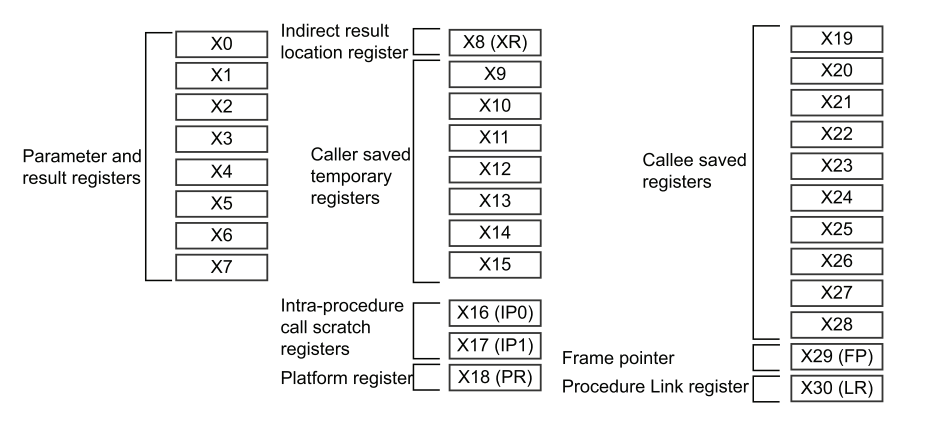
Common ARM Registers

sp(stack pointer) is a special register. Features:
- Not
x0~x30- Specifically used for Stack pointer
- Points to the current stack top
Instruction classification:
- Memory load and store instructions
- Multi-byte memory load and store
- Arithmetic and shift instructions
- shift operation
- Bit manipulation instructions
- Conditional operations
- Branch instructions
- Exclusive memory access instructions
- Memory barrier instructions
- Exception handling instructions
- System register access instructions
Load and store instructions
- LDR
- STR
Exercise 1: ldr instruction

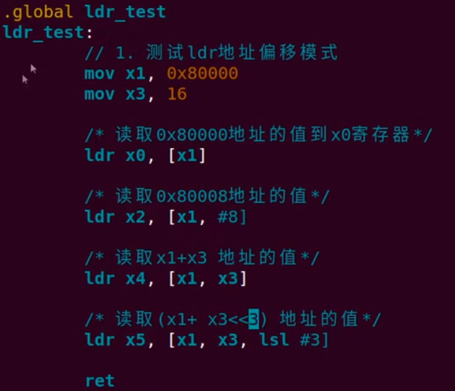
Note: there should be no space in the middle of ‘lsl #3’.
When extended as lsl, the amount depends on the data width being accessed: #0 for 8-bit, #1 for 16-bit, #2 for 32-bit, #3 for 64-bit (as defined by the ARM documentation).
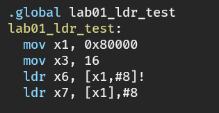
Exercise 2: ldr pre-indexed and post-indexed addressing modes

Exercise 3: str pre-indexed and post-indexed addressing modes

ldr label (literal)
ReadPC+labelthe value of
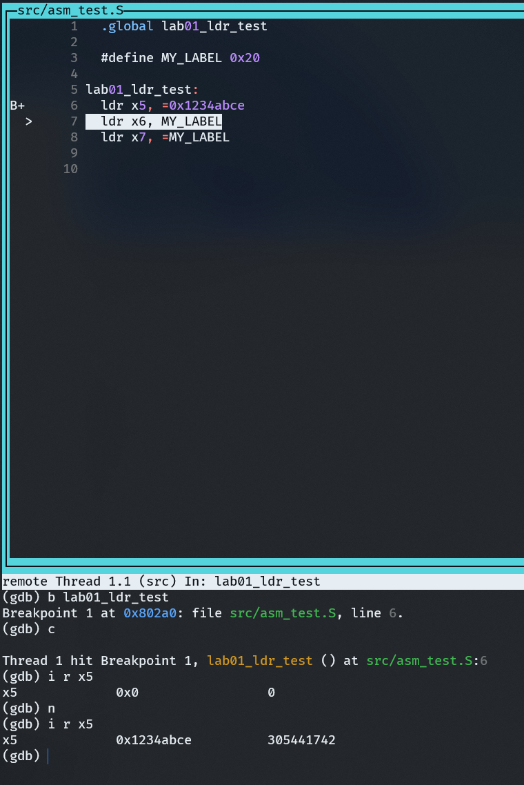
Exercise 4: ldr pseudo-instruction


- Instruction: each instruction corresponds to a CPU operation
- Pseudo-instruction: a command issued to the compiler; it is an operation processed by the assembler during assembly of the source program. It can perform functions such as processor selection, defining program modes, defining data, allocating storage areas, and indicating program termination. In short, it can be decomposed into a set of several instructions.
- The ldr instruction can be either a large-range address-loading pseudo-instruction or a memory access instruction. When its second operand is preceded by ‘=’, it is a pseudo-instruction; otherwise, it is a memory access instruction.
- The ldr pseudo-instruction has no immediate value access restriction.
ldr x6, MY_LABEL is a memory access instruction
ldr x7, =MY_LABEL is an ldr pseudo-instruction
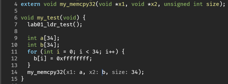
Exercise 5: Implementing memcpy in assembly

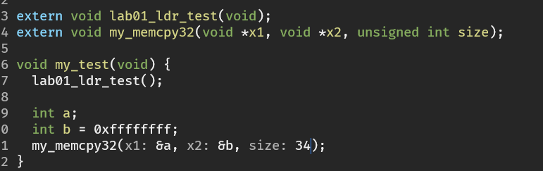
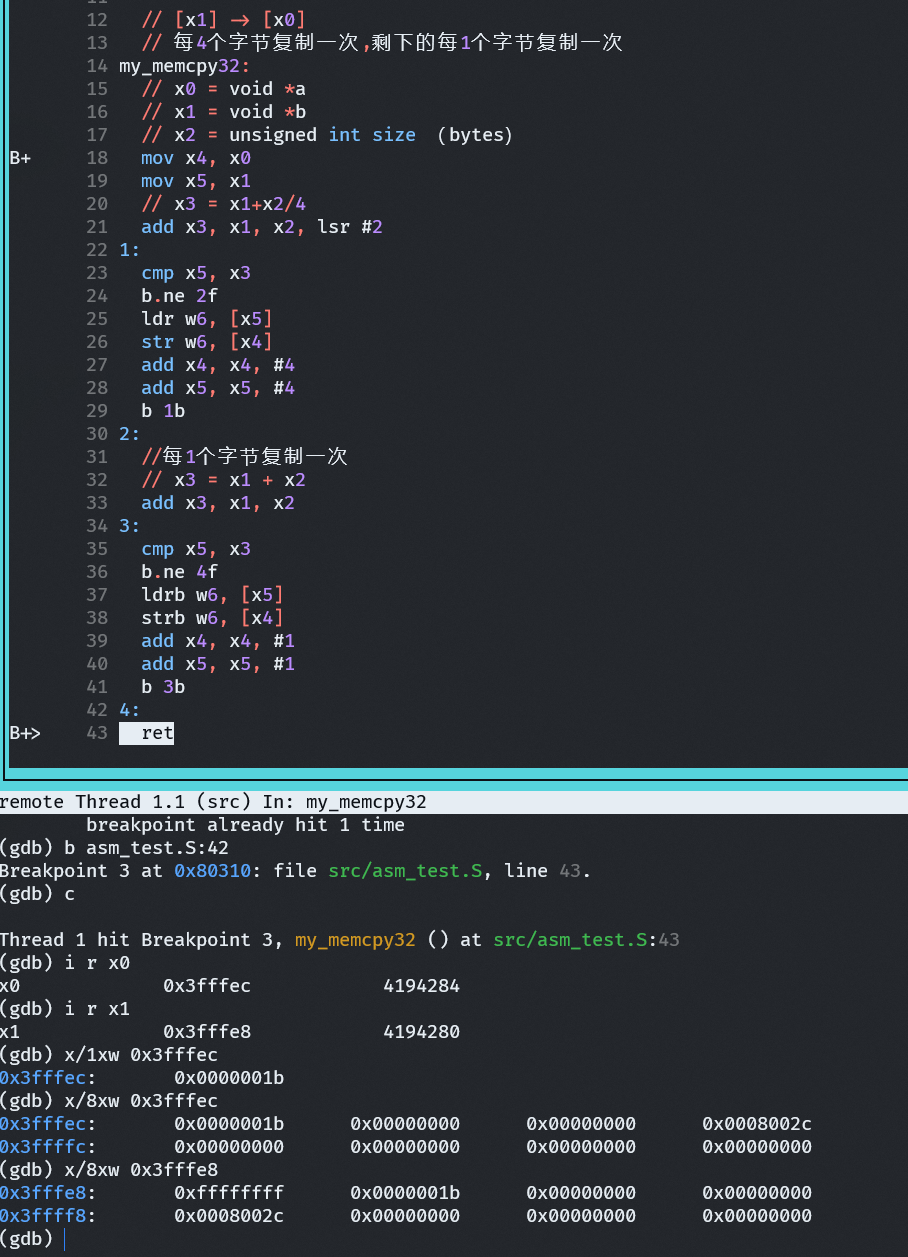
It can be seen that 0xffffffff was not copied over, because the starting address is not four-byte aligned.

mov instruction
- 16-bit immediate

LDP and STP
Provided in the A32 instruction setLDMandSTMTo implement multi-byte memory load and store, in the A64 instruction set, LDM and STM instructions are no longer provided; instead, LDP and STP instructions are used.
- LDP and STP can load and store 16 bytes with a single instruction.

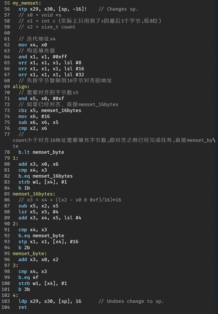
Exercise 6: memset

Exercise 7: Pitfall
Load a very large value into a general-purpose register, e.g., 0xffff_0000_ffff_ffff
Load the value of a register, e.g., the sctrl_el1 register


Note that using ldr may generate a literal pool; it is better to use the adrp instruction.
Store instruction variants
| Instruction | Meaning (full name) | Access size | Sign extension |
|---|---|---|---|
| LDR | Load Register | 32-bit (W register) or 64-bit (X register) | Unsigned |
| LDRSW | Load Register Signed Word | 32-bit → sign-extend to 64-bit | signed |
| LDRB | Load Register Byte | 8-bit → zero-extend to 32/64-bit | Unsigned |
| LDRSB | Load Register Signed Byte | 8-bit → sign-extend to 32/64-bit | signed |
| LDRH | Load Register Halfword | 16-bit → zero-extend to 32/64-bit | Unsigned |
| LDRSH | Load Register Signed Halfword | 16-bit → sign-extend to 32/64-bit | signed |
| LDRQ | Load Register Quadword (NEON/SIMD register) | 128-bit (V register) | Unsigned |
| STR | Store Register | 32-bit or 64-bit | Unsigned |
| STRB | Store Register Byte | 8-bit | Unsigned |
| STRH | Store Register Halfword | 16-bit | Unsigned |
Supplementary notes
- Unsigned loads (LDR, LDRB, LDRH): high bits are zero-filled
0。 - Signed loads (LDRSB, LDRSH, LDRSW): sign extension is performed (if the most significant bit is 1, it is extended to 1).
- If accessing and storing 4 bytes or 8 bytes, both use ldr and str, except that the destination register uses wn or xn.
STRThe series of instructions has no signed version, because when storing, they are written to memory as-is,**No sign extension, zero extension, or any padding operation is performed.**But note the register bit width, e.g., xn and wn are different.- AArch64 defaults to little-endian (low address stores low byte).
- There is also a categoryatomic load/store instructions(
LDAXR、STLXRetc.) used for lock operations.
Arithmetic and shift instructions
The four condition code flags NZCV in the pstate processor state

add addition instruction
The ordinary addition instruction add
- Addition using registers
- Addition using immediate values
- Addition using shift operations
adds instruction - affects condition flags (carry)
Mainly affects the C flag (unsigned overflow)
sub subtraction instruction
The ordinary subtraction instruction
subs instruction - affects condition flags (C flag)
adc instruction (addition with carry)

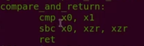
sbc instruction (subtraction with carry)

Wd = Wn - Wm - 1 + C
cmp comparison instruction
Compare the size of two numbers, implemented internally using the subs instruction, affecting the C flag.
Equivalent to
1 | SUBS XZR, <Xn>, #<imm> |
When both x1 and x2 are unsigned numbers
1 | cmp x1, x2 |
x1-x2 = x1 + ~x2 + 1 (two’s complement subtraction, C=0 when borrow occurs)
When x1 >= x2 (unsigned), C=1 (no borrow)
When x1 < x2 (unsigned), C=0 (borrow occurs)
Exercise 1: C condition flags of adds and cmp instructions

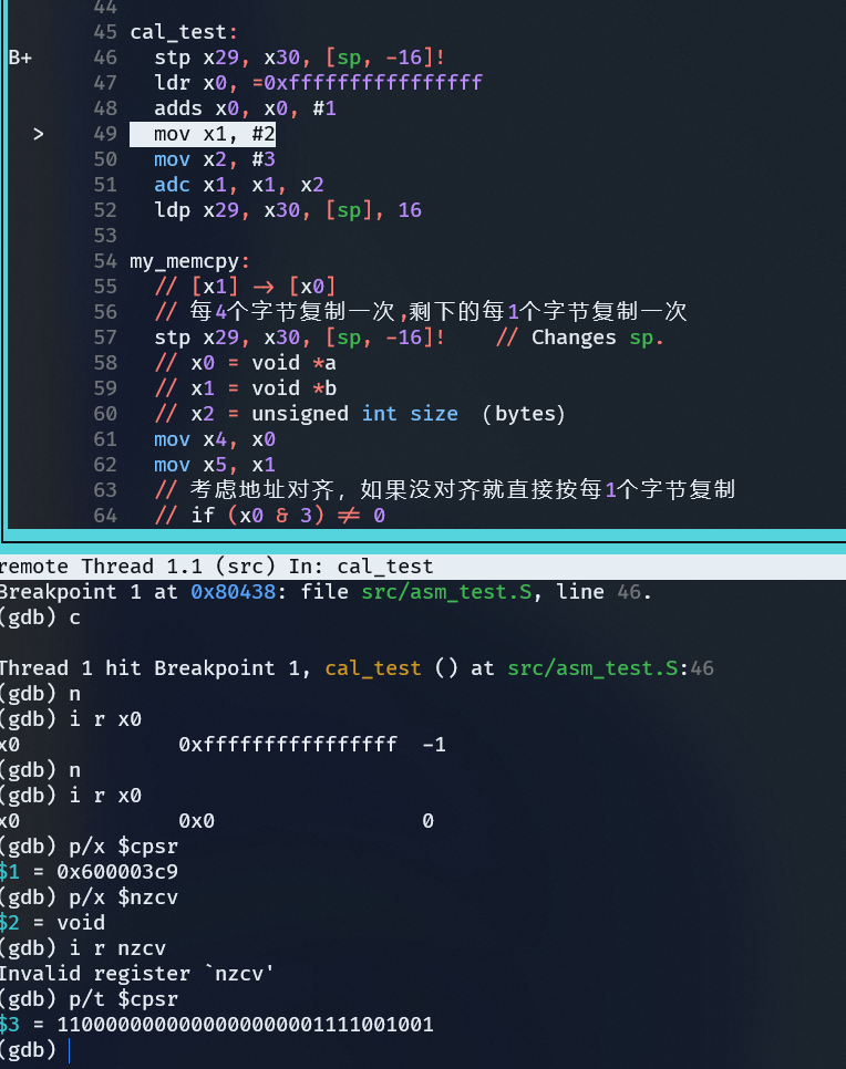
| bit | Name | meaning |
|---|---|---|
| 31 | N | Result is negative |
| 30 | Z | Result is zero |
| 29 | C | Unsigned comparison: no borrow (Carry) |
| 28 | V | Signed overflow |
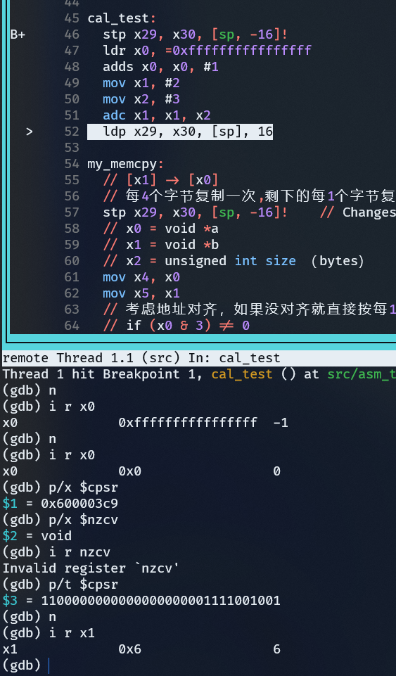
Exercise 2: cmp and sbc instructions

shift operation
- lsl logical left shift
- lsr logical right shift
- asr arithmetic right shift
- ror rotate right

Bitwise AND operation
- and AND operation
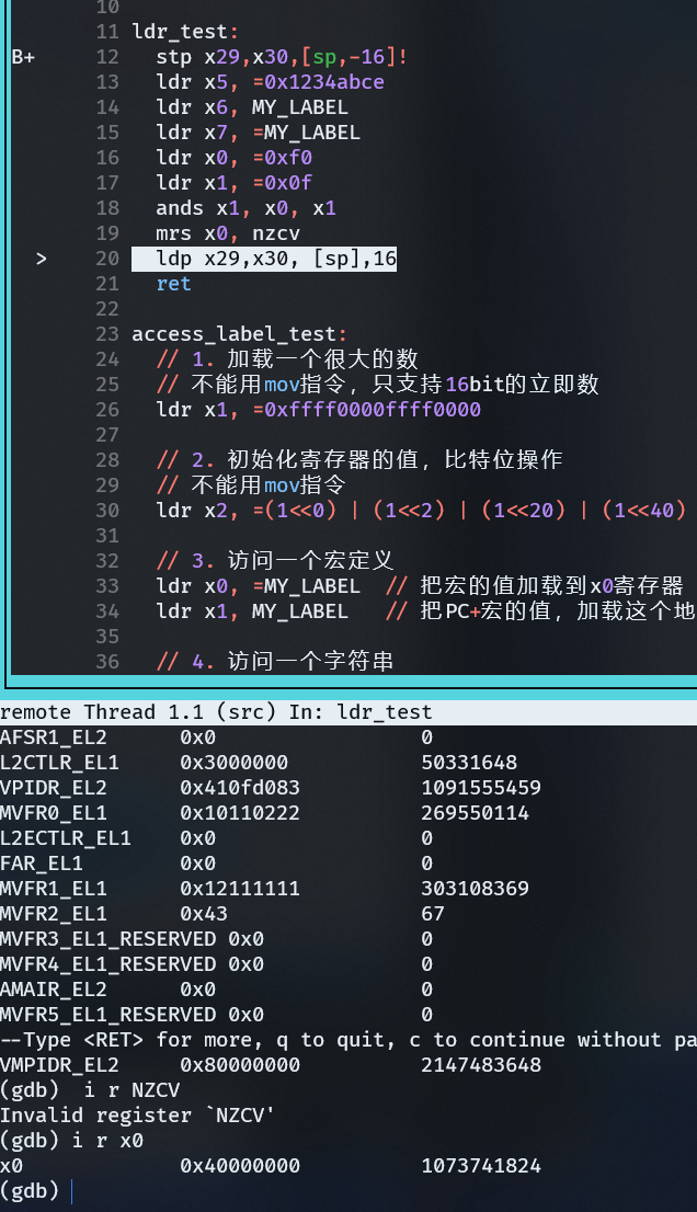
- ands Bitwise AND operation and set flags (affects N/Z/C/V)
Bitwise OR operation
- orr OR operation
- eor XOR operation

Bitwise clear
- bic Bit clear instruction
Uncommon
Exercise 3: Testing the ands instruction and the Z flag

Bitfield insert operation
Bitfield

bfi Bitfield insert instruction
bitfield insert

Xd: Destination register
Xn: Source register
lsb:Least Significant Bit, i.e. The index of the lowest bit position in the destination register Xd where insertion starts(counting from 0).
width: The bit width (number of bits) to insert.

UBFX unsigned bitfield extract instruction
SBFX signed bitfield extract instruction

Note: counting starts from 0.
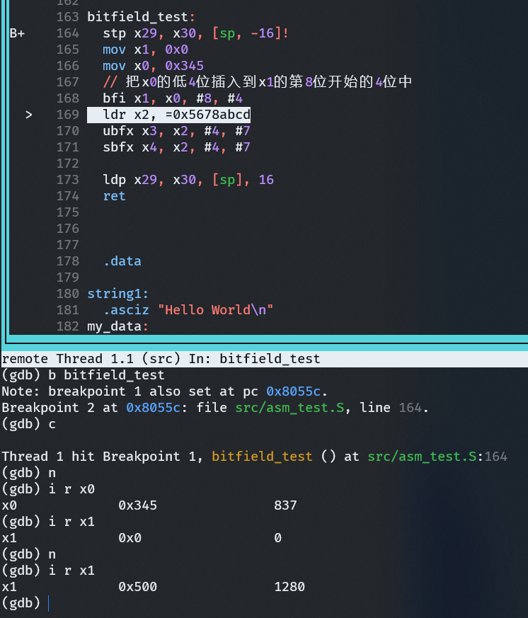
Exercise 4: Testing bitfield instructions


Multiplication and division instructions
Multiplication:
| Instruction | Description |
|---|---|
| MADD | Multiply-Add:Xd = (Xn * Xm) + Xa |
| MNEG | Multiply-Negate:Xd = -(Xn * Xm) |
| MSUB | Multiply-Subtract:Xd = Xa - (Xn * Xm) |
| MUL | Multiply:Xd = Xn * Xm(low 64 bits of result) |
| SMADDL | Signed Multiply-Add Long: 32-bit * 32-bit → 64-bit, plus addend |
| SMNEGL | Signed Multiply-Negate Long: 32-bit * 32-bit → 64-bit, negate |
| SMSUBL | Signed Multiply-Subtract Long: 32-bit * 32-bit → 64-bit, perform subtraction |
| SMULH | Signed Multiply returning High half: take the high 64 bits of the 128-bit result (signed) |
| SMULL | Signed Multiply Long: 32-bit * 32-bit → 64-bit |
| UMADDL | Unsigned Multiply-Add Long: unsigned version |
| UMNEGL | Unsigned Multiply-Negate Long: unsigned version |
| UMSUBL | Unsigned Multiply-Subtract Long: unsigned version |
| UMULH | Unsigned Multiply returning High half: take the high 64 bits (unsigned) |
| UMULL | Unsigned Multiply Long: unsigned 32-bit * 32-bit → 64-bit |
Division:
| Instruction | Description |
|---|---|
| SDIV | Signed Divide: signed division |
| UDIV | Unsigned Divide: unsigned division |
Comparison and branch instructions
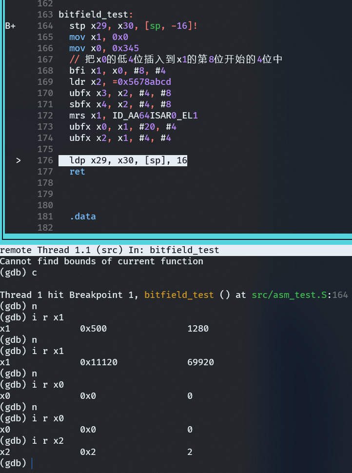
Exercise 5: Using bitfield instructions to read registers

Note that instructions like ubfx can only extract bit fields from ordinary register values, and cannot directly extract system registers, so you need to first use msr to store the system register into a general-purpose register.
Read system register (move register from system)
1 | mrs x1, ID_AA64ISAR0_EL1 |
Write system register (move system from register)
1 | msr ID_AA64ISAR0_EL1, x1 |
⚠️ But note: many CPU feature registers (such as
ID_AA64ISAR0_EL1) are read-only, soMSRWriting to this register usually triggers an exception, so it cannot be modified arbitrarily.
Count leading zeros instruction clz
clz: counts the number of leading zeros before the most significant set bit.

Comparison instruction
cmp
Compare two numbers
cmp x1, x2
x1-x2
cmn
Negative comparison
cmn x1, x2
x1+x2
Conditional operation suffix
| Condition suffix | meaning | Flag | Condition code | Abbreviation description |
|---|---|---|---|---|
| EQ | Equal | Z=1 | 0b0000 | Equal |
| NE | Not equal | Z=0 | 0b0001 | Not Equal |
| CS/HS | Unsigned greater than or equal | C=1 | 0b0010 | Carry Set / Higher or Same |
| CC/LO | Unsigned less than | C=0 | 0b0011 | Carry Clear / Lower |
| MI | Negative | N=1 | 0b0100 | Minus |
| PL | Positive or zero | N=0 | 0b0101 | Plus |
| VS | overflow | V=1 | 0b0110 | Overflow Set |
| VC | No overflow | V=0 | 0b0111 | Overflow Clear |
| HI | Unsigned greater than | (C=1) && (Z=0) | 0b1000 | Higher |
| LS | Unsigned less than or equal | (C=0) ∨ (Z=1) | 0b1001 | Lower or Same |
| GE | Signed greater than or equal | N = V | 0b1010 | Greater or Equal |
| LT | Signed less than | N ≠ V | 0b1011 | Less Than |
| GT | Signed greater than | (Z=0) && (N=V) | 0b1100 | Greater Than |
| LE | Signed less than or equal | (Z=1) ∨ (N≠V) | 0b1101 | Less or Equal |
| AL | Unconditional execution | – | 0b1110 | Always |
| NV | Unconditional execution | – | 0b1111 | Never (reserved, generally not used) |
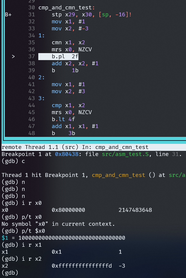
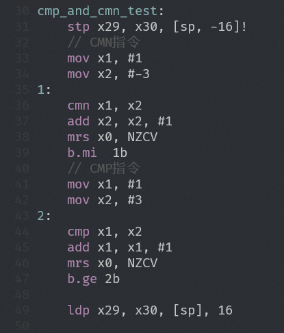
Exercise 1: cmp/cmn instructions and conditional operation suffixes

NZCV register structure diagram

1234 | ┌───┬───┬───┬───┐│ N │ Z │ C │ V │└───┴───┴───┴───┘ 31 30 29 28 ← 在 PSTATE 或 NZCV 系统寄存器的位位置 |
N (Negative flag)
- Result is negative (most significant bit of signed number is 1) → N=1
- Otherwise N=0
Z (Zero flag)
- Result equals 0 → Z=1
- Otherwise Z=0
C (Carry flag)
- Addition: carry occurs → C=1
- Subtraction: no borrow (i.e., operand 1 ≥ operand 2) → C=1
- Otherwise C=0
V (Overflow flag)
- Signed addition/subtraction overflow (result out of representable range) → V=1
- Otherwise V=0
Conditional select instructions
Used with the cmp instruction
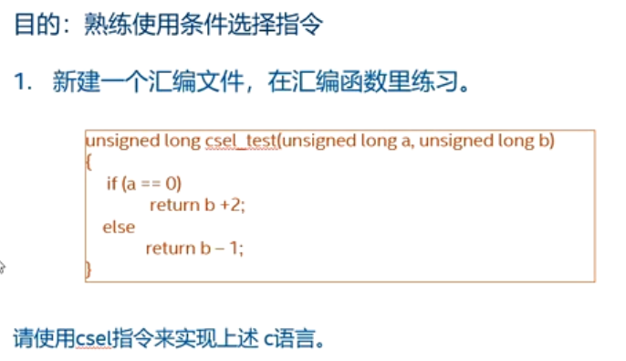
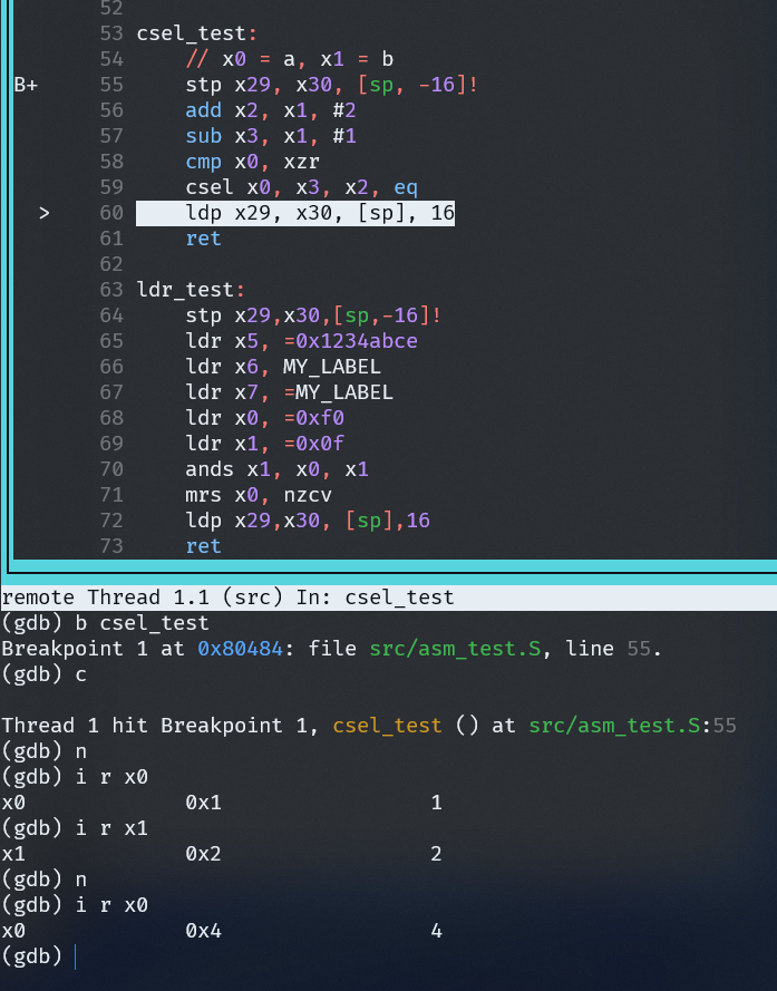
csel

cset
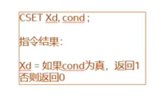
csinc
Conditional Select Increment

Exercise 2: Conditional select instructions
Branch instructions
b unconditional branch
Branch instruction, unconditional branch, does not return
Branch range: PC+/- 128MB
b.cnd conditional branch instruction
Conditional branch instruction, does not return
cnd is the condition code suffix
Branch range: PC+/- 1MB
bx branch to the address specified by a register
Branch to the address specified by a register, does not return
bl (Branch with Link) branch with return address
With return address (PC+4 => x30), suitable for calling subroutines
The return address is saved to x30; it stores the parent function’s PC+4.
Branch range: PC+/- 128MB
blx (Branch with Link to Register)
Jump to the address specified by the register, and can return.
The return address is saved to x30; it stores the parent function’s PC+4.
Return instruction.
ret
Return from a subroutine; usually the return address is stored in x30.
eret
Return from the current exception mode; this can usually achieve mode switching, e.g., switching from EL1 to EL0.
It returns from the current exception mode; it restores PSTATE from SPSR, obtains the jump address from ELR, and returns to that address.
Exercise 3: Why does it run away after ret?


Pitfalls and traps.
bl instruction: used to call a subroutine; it writes the return address into the x30 register, and the return address is PC+4.
In a function, calling a subroutine with bl may clobber the parent function’s lr register, and then the parent function’s ret will run away.
Simply put, the subroutine changed the value of the x30 register and did not restore it when returning.
Compare and branch instructions.
cbz cbnz tbz tbnz
| Instruction | Abbreviation meaning. | Description. |
|---|---|---|
| CBZ | Compare and Branch if Zero | Checks whether the value of the specified register is zero; if zero, jumps to the target address. Jump range is +/- 1MB. |
| CBNZ | Compare and Branch if Non-Zero | Checks whether the value of the specified register is non-zero; if non-zero, jumps to the target address. Jump range is +/- 1MB. |
| TBZ | Test Bit and Branch if Zero | Checks whether a certain bit of the specified register is 0; if that bit is 0, jumps to the target address. Jump range is +/- 32KB. |
| TBNZ | Test Bit and Branch if Non-Zero | Checks whether a certain bit of the specified register is 1; if that bit is 1, jumps to the target address. Jump range is +/- 32KB. |
Other important instructions.
PC-relative address load instruction.
- adr instruction: loads the address of a label relative to the PC, with a range of +/- 1MB.

- adrp instruction: loads the address of a label relative to the PC; it only loads the 4KB-aligned address of the label, with a range of +/- 4GB.


Exercise 1: Testing the ADRP and LDR instructions


What exactly is the difference between ADRP and LDR?
Pitfalls and traps:

LDR pseudo-instruction: loads an absolute address
ADRP instruction: loads a PC-relative address
When the link address equals the run address
The address loaded by the LDR pseudo-instruction is the same as the address loaded by the ADRP instruction.
- When the link address does not equal the run address
LDR pseudo-instruction address: loads the link address (also called virtual address)
ADRP instruction: loads the PC value at the current run address plus the label’s offset, i.e., the label’s address at runtime (also called physical memory).
Exercise 2: Pitfalls of the ADRP and LDR instructions

Exclusive memory load and store instructions
- LDXR instruction
Exclusive memory load instruction: loads the memory address from memory to a general-purpose register in an exclusive manner.
- STXR instruction
Exclusive memory store instruction
- ldxr loads memory, but it monitors access to this memory through an exclusive monitor. The monitor marks this memory address as exclusive access, ensuring that it is accessed in an exclusive manner.

- stxr is a conditional memory store. The memory address previously marked by ldxr is stored in an exclusive manner. Note that the first register is w0.


- The ldxr and stxr instructions usually need to be used in pairs.
- The Linux kernel often uses them to implement atomic access, such as atomic._write(),atomic_set_bit()
- The spinlock mechanism can be simply implemented using the ldxr and stxr instructions.
Exercise 3: Using the ldxr and stxr instructions


Exception handling instructions
| Instruction | Name | Description |
|---|---|---|
| SVC #imm | System call instruction(Supervisor Call) | The application, viaSVCThe instruction jumps from user mode to the kernel-mode operating system, usually entering EL1 exception level, to trigger a system call. |
| HVC #imm | Virtualization system call instruction(Hypervisor Call) | The host operating system, viaHVCThe instruction goes from EL1 to EL2, invoking the hypervisor, for virtualization support scenarios. |
| SMC #imm | Secure monitor system call instruction(Secure Monitor Call) | The host operating system or monitor program, viaSMCThe instruction goes from the Non-secure World to the Secure World, usually triggering an EL3 exception, for the TrustZone security mechanism. |
System register access instructions
| Instruction | Description |
|---|---|
| MRS | Read the value of a system register into a general-purpose register (Move Register from System). |
| MSR | Write the value of a general-purpose register into a system register (Move Register to System). |
Memory barrier instructions
| Instruction | Full name | Function | Strength | Example usage |
|---|---|---|---|---|
| DMB | Data Memory Barrier | GuaranteeExecution order of memory access instructions(e.g., read-after-write will not be reordered) | Medium | Inter-core shared data communication |
| DSB | Data Synchronization Barrier | Wait for all memory accesses to completethen execute subsequent instructions | Strong | Cache synchronization before and after peripheral register reads/writes |
| ISB | Instruction Synchronization Barrier | Clear instruction pipeline and cache, force refetch | Special | After changing system state registers, force instruction flush |
- DMB
Effect: Guarantees the order of memory accesses, but does not block execution.
Example:
123 | str x0, [x1] // Write datadmb sy // Ensure write operation completesldr x2, [x3] // then read other data |
- DSB
Effect: Must wait for all previous memory operations to complete before continuing with subsequent instructions.
Example:
123 | str x0, [x1] // Write datadsb sy // Wait for write to completeisb // Ensure that subsequent execution uses the latest code |
- ISB
Effect: Clears the CPU instruction prefetch cache, usually used after modifying system control registers.
Example:
12 | msr sctlr_el1, x0 // Modify system control registerisb // Force instruction stream flush |
Detailed explanation of DMB/DSB instruction parameters (granularity and scope of memory barriers)
| Parameters | Access order control | Shareability | Description |
|---|---|---|---|
SY | Read/Write | Full system shareable | Strongest,All processors and devicesVisible, commonly used in device drivers or critical synchronization |
ST | Write | Full system shareable | Only forWrite operationEstablish order |
LD | Read | Full system shareable | Only forRead operationEstablish order |
ISH | Read/Write | Inner Shareable (internal shareable) | Used when multiple cores share the same L2 cache |
ISHST | Write | Inner Shareable | Inner shareable domain’sWrite barrier |
ISHLD | Read | Inner Shareable | Inner shareable domain’sRead operation barrier |
NSH | Read/Write | Non-shareable (not shared) | This core’s private memory usage |
NSHST | Write | Not shared | This core’s private write barrier |
NSHLD | Read | Not shared | This core’s private read barrier |
OSH | Read/Write | Outer Shareable (externally shared) | Used when sharing among multiple L2s |
OSHST | Write | Outer Shareable | Outer Shareable write barrier |
OSHLT | Read | Outer Shareable | Outer Shareable read barrier |
Overview Summary
The instruction set running in the AArch64 execution state; 64 refers to its execution environment, not the instruction length.
The instruction length is 32 bits, not 64 bits.
31 general-purpose registers; xn is 64-bit, wn is 32-bit.
Zero registers: xzr, wzr
PC is not a general-purpose register and cannot be directly accessed as a general-purpose register.
x30 is used as the link register (LR) for function return.
ELR_ELx is used to return from exceptions.
Each exception level has its own stack SP, e.g., SP_ELx_EL0, SP_EL1
SP is not a general-purpose register.
Registers for SIMD and floating-point operations.
Qn (128-bit, 16 bytes), Dn (64-bit), Sn (32-bit), Hn (16-bit), Bn (8-bit)
PSTATE(Processor State Register)It is not a standalone physical register., but rathera collection of processor states composed of multiple bit fields.。PSTATEThe value controls the current state of the CPU, including exception masking, current exception level, condition codes, etc.
| field | Meaning description |
|---|---|
NZCV | Condition code flags (ALU Flags) are used for conditional branches, etc.:N(negative),Z(zero),C(carry),V(overflow) |
Q | Saturation overflow flag, set only when certain SIMD saturating operations overflow in AArch32. |
DAIF | Exception mask bits:D: debug exception maskA: SError maskI: IRQ interrupt maskF: FIQ interrupt mask |
SPSel | SP register selection (AArch64 only) controls whether to useSP_EL0orSP_ELx |
CurrentEL | Current exception level (EL0/EL1/EL2/EL3) affects privileged access and execution. |
E | Byte order selection (AArch32) controls whether data access is little-endian or big-endian. |
IL | When the illegal instruction flag is set to 1,all instructions will be executed as UNDEFINED, for debugging |
SS | The single-step execution flag (Software Stepping) is used in conjunction with the debugger, triggering an exception after each instruction is executed. |
- Load and store instructions
| Instruction | Type | Data size | Sign-extend? | Store/Load target |
|---|---|---|---|---|
LDR | Normal load | By register | No | Any width |
LDRSW | Load signed word | 32-bit | ✔ (sign-extended to 64-bit) | Xn only |
LDRB | Load byte | 8-bit | No | Wn/Xn |
LDRSB | Load signed byte | 8-bit | ✔ | Wn or Xn |
LDRH | Load halfword | 16-bit | No | Wn/Xn |
LDRSH | Load signed halfword | 16-bit | ✔ | Wn or Xn |
STRB | Store byte | 8-bit | N/A | — |
STRH | Store halfword | 16-bit | N/A | — |
Instruction suffix meaning
| Suffix | meaning |
|---|---|
B | Byte(8-bit) |
H | Halfword(16-bit) |
W | Word(32-bit) |
S | Sign-extended |
| No suffix | By default, load or store according to the bit width of the destination register. |
- Multi-byte load and store instructions
- The A64 instruction set has removed the ldm, stm, push, and pop instructions.
- ldp and stp are used to implement multi-byte load and store instructions.
PC-relative instructions
ldr x0, =label(pseudo-instruction)
- meaning: load
labelthe address of (link address) tox0。 - Implementation method: the assembler will
.rodatagenerate a constant table in the region,ldrin fact, it loads the address from the constant table. - Applicable scenarios: can be used anywhere, butit depends on link-time address information, and caution is needed in systems that support relocation.
ldr x0, label
- meaning: load
labelthe value at the address intox0Middle. - Note: here
labelis an address; the data it points to is loaded into the register (not the address itself). - Unlike the above: this is not a load address, butreading data through the address。
adr x0, .
- meaning: load the current PC value into
x0Middle. - Common scenarios: locate the current code position (e.g., for implementing Position-Independent Code).
adrp x0, label
- meaning: load
labelof the page where it resides**page start address (4KB aligned)**load intox0Middle. - Purpose:
- often used for position-independent code (PIC)。
- combined with
addto implement full address loading:
| Flags | meaning | Common triggering conditions |
|---|---|---|
N | Negative (sign) flag: set when the result is negative. | such assubs x0, x1, x2getting a negative number |
Z | Zero flag: set when the result is zero. | such assubs x0, x1, x1, the result is 0 |
C | Carry flag: set when there is a carry in unsigned addition, or no borrow in unsigned subtraction (C=1 means no borrow). | such asadds,subs,adc,sbc |
V | Overflow flag: set when signed addition or subtraction overflows. | such asadds,subsoverflow |
Recommended documentation
arm8.6 Chapter C3 A64 Instruction Set Overview
Pitfalls and traps: runs on QEMU but not on the board
Pitfall 1: ldr instruction loads a macro


In bare-metal programming, the MMU is not enabled, so memory attributes are always treated as Device memory.
The ldr instruction accesses 8 bytes. If the address is not 8-byte aligned, it triggers an alignment exception, i.e., a Data Abort.
Solution:
123 | ldr x6, MY_LABEL// Modifyldr w6, MY_LABEL |
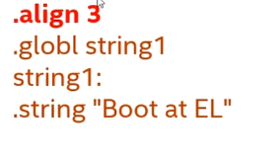
Pitfall 2: ldr instruction loads a string

This is also caused by alignment, because the starting address of string1 cannot be guaranteed to be 8-byte aligned.
Solution: align string1 to 8 bytes.
Alignment access summary
- For normal memory, unaligned access is supported. (The MMU needs to be enabled and the memory attribute set to normal.)
- You can separately configure unaligned access to trigger an exception (by setting SCTLR_Elx.A).
- For Device memory, unaligned access triggers a Data Abort exception.
- On systems without the MMU enabled, for example, our experimental code directly accessing DDR is treated as device memory.
- Instruction prefetch requires 4-byte alignment; otherwise, an exception is triggered.
- Normal memory supports unaligned access.
- Condition:
- MMU enabled MMU(Memory Management Unit);
- and the memory region’s attribute is set to Normal memory;
- Result:
- Supports unaligned access to words (4 bytes), half-words (2 bytes), and bytes (1 byte);
- Can perform cross-boundary access without triggering an exception;
- Unaligned access exception configuration (SCTLR_ELx.A bit)
- SCTLR_ELx.A Controls whether to check unaligned access(Alignment Check):
A = 0(Default): Does not check unaligned access (proceeds normally if the memory type allows it);A = 1:Force alignment checkingOnce an unaligned access occurs, it triggers Alignment fault exception (Data Abort);
- Device memory does not support unaligned access
- Features:
- Regardless of whether MMU is enabled, Device memory type alwaysdoes not allow unaligned access;
- Consequence:
- Once an unaligned address is accessed (e.g., accessing
0x100332-bit data), it will trigger Data Abort exception;
- Once an unaligned address is accessed (e.g., accessing
- Application example:
- In the experimental environment, direct mapping access DDR, peripheral registers etc., are usually defined as Device memory type;
- Access to these regions must be aligned; for example, accessing 32-bit data must be 4-byte aligned;
- Instruction fetch requires
- instruction address must be 4-byte aligned(i.e., the lowest two bits of the address must be 0);
- otherwise it will trigger Instruction Abort exception;
- Reason: ARMv8 instructions are stored and fetched in 4-byte units, and cannot be decoded and executed from an unaligned position.
Pit 3: Data size of store instructions
When using the str instruction to set registers, be sure to pay attention to the bit width of the register, otherwise a system crash may occur.
The peripheral register bit width on the Raspberry Pi 4B is 32-bit, i.e., 4 bytes.

Pit 4: The big pitfall of ldxr

The use of the ldxr instruction has many restrictions.
- First, ensure that the accessed memory is normal memory and is shareable.

- If accessing device memory, such as when the MMU is not enabled, then the CPU IP core must support exclusive access to device memory. This requires consulting the description in the specific CPU IP manual.
For example: Cortex-A72 MPCore Processor Technical Reference Manual, Section 6.45

Solution:
Fill in the page table properly, enable MMU and cache, and then you can use ldxr and stxr.
Implement serial port printing in assembly


🧱 1. GPIO initialization (pin multiplexing configuration)
1234567 | ldr x1, =GPFSEL1ldr w0, [x1]and w0, w0, #0xffff8fff // Clear GPIO14 function select bits (bits 12-14)orr w0, w0, #0x4000 // Set GPIO14 to ALT0 (UART0_TXD)and w0, w0, #0xfffc7fff // Clear GPIO15 function select bits (bits 15-17)orr w0, w0, #0x20000 // Set GPIO15 to ALT0 (UART0_RXD)str w0, [x1] |
✅ Effect: Set GPIO14 and GPIO15 to UART function (ALT0 mode).
🧱 2. Disable pull-up/pull-down (Pi 3B only)
1234567891011121314151617181920212223242526 | #ifdef CONFIG_BOARD_PI3B ldr x1, =GPPUD str wzr,[x1] // delay 150 cycles mov x0, #1501: sub x0, x0, #1 cmp x0, #0 bne 1b ldr x1, =GPPUDCLK0 ldr w2, #0xc000 // Applies to GPIO14 and GPIO15 str w2, [x1] // delay again mov x0, #1502: sub x0, x0, #1 cmp x0, #0 bne 2b ldr x1, =GPPUDCLK0 str wzr, [x1] isb#endif |
✅ Disable pull-up/pull-down on GPIO14/15, matching the BCM2837 initialization flow.
🧱 3. UART initialization
123456789101112131415161718192021222324252627 | // Disable UARTldr x1, =U_CR_REGstr wzr, [x1]// Set baud rateldr x1, =U_IBRD_REGmov w2, #26 // Integer Baud Rate Divisorstr w2, [x1]ldr x1, =U_FBRD_REGmov w2, #3 // Fractional Baud Rate Divisorstr w2, [x1]// Set data formatldr x1, =U_LCRH_REGmov w2, #0x70 // FIFO enable + 8-bit word lengthstr w2, [x1]// Disable interruptsldr x1, =U_IMSC_REGstr wzr, [x1]// Enable UART (TX/RX/UART enable)ldr x1, =U_CR_REGmov w2, #0x301 // UARTEN | TXE | RXEstr w2, [x1]isb |
✅ Correctly configure baud rate and data format (8N1, FIFO), then enable UART.
You are using:
Baud rate = UARTCLK / (16 * (IBRD + FBRD/64))
Assuming UARTCLK = 48 MHz, the baud rate is approximately 115200.
🧱 4. Single character output function put_uart
1234567891011 | put_uart: ldr x1, =U_FR_REG1: ldr w2, [x1] and w2, w2, #0x20 // Check TXFF (Transmit FIFO full) cmp w2, #0 b.ne 1b // If FIFO is full, wait ldr x1, =U_DATA_REG str w0, [x1] // Write character ret |
✅ Waits for FIFO availability before sending the character.
🧱 5. String output function put_string_uart
1234567891011 | put_string_uart: mov x4, x0 // x0: pointer to string mov x6, x30 // Save return address1: ldrb w0, [x4] // Read one byte (character) bl put_uart add x4, x4, 1 cmp w0, #0 bne 1b mov x30, x6 ret |
✅ Input: x0 = string address, prints it until NULL (0x00) is encountered.