Timeline
Timeline
2025-05-22
- init
This article introduces the principles and implementation of I/O virtualization, focusing on three approaches: pure software-based device emulation and paravirtualization, direct assignment, and single-root I/O virtualization (SR-IOV). It first analyzes that device emulation and paravirtualization must go through the VMM software layer, resulting in high CPU overhead, limited throughput, and inability to leverage advanced hardware features. It then introduces direct assignment technology, which uses hardware assists such as Intel VT-x/VT-d to bypass the virtualization emulation layer, allowing virtual machines to directly access physical devices and significantly improving performance, but with the scalability limitation that one physical device can only be assigned to one virtual machine. Finally, it presents SR-IOV as a natively shareable device, which provides each virtual machine with independent memory space, work queues, and interrupt mechanisms, enabling virtual machines to directly connect to I/O devices without VMM involvement in data transfer, thereby achieving efficient sharing of physical I/O resources among multiple virtual machines while maintaining performance.
I/O virtualization (IOV)
I/O virtualization (IOV) refers to sharing a single I/O resource among multiple virtual machines. Methods for implementing IOV include:
- pure software implementationsharing approach,
- hardware-supportedsharing approach,
- and hybrid approach combining software and hardware。
Sharing based on pure software implementation
- device emulation (full virtualization):
Device emulation mode imitates widely supported real hardware devices (e.g., Intel’s 1Gb NIC), so that the operating system in the virtual machine can continue to use the drivers it already supports. The hypervisor (VMM, Virtual Machine Monitor) emulates this I/O device to ensure compatibility, processes I/O operations before the actual I/O, and then forwards them to the actual physical device (which may be different from the emulated device).
⚠️ Problem: As a result, I/O operations must go through two layers of I/O stacks—one inside the virtual machine and another in the hypervisor—which increases overhead and reduces performance. - split-driver model (paravirtualization):
This method is similar to device emulation, but itno longer emulates a traditional device, but instead adopts afront-end and back-end driver cooperation approach:- The front-end driver runs in the guest operating system of the virtual machine;
- The back-end driver runs in the hypervisor.
The two work together and are specifically optimized for resource sharing. Compared with device emulation, the advantages of this method are:No need to emulate the entire device, resulting in better performance and lower overhead. The back-end driver communicates directly with the actual physical device.
| Method | Advantages | Disadvantages |
|---|---|---|
| device emulation | Good compatibility, can use existing drivers | Poor performance, requires going through two layers of I/O stack |
| split-driver model | Better performance, optimized sharing | Requires writing dedicated drivers for the front-end and back-end |

Disadvantages of software-based sharing
Whether it isdevice emulationorsplit-driver (i.e., paravirtualized driver), they usually can only provide a part of the physical hardware functionality, and therefore maycannot utilize the advanced features provided by the physical device。
In addition, when the virtual machine monitor (VMM) implements a virtual software switch (used to forward packets between multiple virtual machines), it may consumea large amount of CPU resources. This CPU overhead will (and usually does)reduce the maximum throughput of I/O devices。
For example: if only device emulation is used, a 10Gbps Ethernet controllercan only achieve a maximum throughput of 4.5 to 6.5 Gbps(this range depends on the architecture of the specific test server).
One of the main reasons is:every packet must pass through the software switch, which requires the CPU to process these packets, creating a performance bottleneck and making it impossible to achieve line rate or near-line-rate transmission capability.
Although software-based I/O virtualization has good compatibility, it also has some obviousperformance bottlenecks and functional limitations, these shortcomings are particularly evident in scenarios with high performance requirements (such as high-frequency trading, data centers, network function virtualization, etc.):
| Disadvantages | Description |
|---|---|
| Incomplete functionality | Unable to access all advanced features of the device, such as hardware acceleration, QoS, SR-IOV, etc. |
| High CPU overhead | Each I/O operation requires VMM intervention, especially in network scenarios, where packet processing goes through a software switch, consuming a large amount of CPU. |
| Limited throughput | A network card with a theoretical 10Gbps speed actually achieves only 4.5~6.5Gbps throughput, far below line rate. |
Direct Assignment
also known asdevice passthrough
The software-based sharing approach adds extra overhead to every I/O operation because there is anemulation layer. The existence of this intermediate layer also brings another effect:Inability to use hardware acceleration features provided by the physical device。
To solve these problems, the physical hardware can bedirectly exposed to the guest operating system (Guest OS), and let it runnative device drivers, thereby reducing the performance loss caused by the intermediate layer.
Hardware vendors (such as Intel) have introduced enhancements for this purpose, used tosupport memory address translationandensure memory protection, enabling the device todirectly perform DMA operations on host memory. These enhancements canBypass the I/O emulation layer of the hypervisor (VMM), therebyimproving the I/O throughput performance of the virtual machine。
A feature of Intel® VT-x technology is that, if configured by the VMM, a virtual machine candirectly access physical addresses. In this way, device drivers in the virtual machine candirectly write to the registers of I/O devices(e.g., configure DMA descriptors, etc.).
Intel® VT-d technology, on the other hand, provides similar capabilities, allowing I/O devices todirectly write to the memory space of the virtual machine(through address translation), for example, to perform DMA operations.
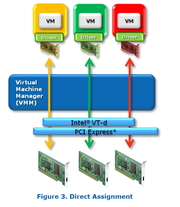
The mechanisms for implementing direct assignmentvary among different vendors, but the basic idea is the same: the hypervisor utilizes and configures technologies such as Intel® VT-x and VT-d to perform address translation during data transmission and reception, ensuring that data can be transferred safely and efficiently between virtual machines and I/O devices.
✅ Advantages:
- Bypass the intermediate emulation layer, reducing CPU overhead;
- Support native drivers, enabling all features of the device (including hardware acceleration);
- Significantly improve performance, especially with notable improvements in throughput and latency;
- Suitable for high-performance scenarios, such as network function virtualization (NFV), GPU-accelerated computing, etc.
⚠️ Issues:
A major problem with direct assignment is itslimited scalability: a physical devicecan only be assigned to one virtual machine。
For example, a dual-port network interface card (NIC) can only be provided to two virtual machines at the same time (each virtual machine occupies one port). However, the number of I/O devices that can be inserted into the system is subject to afundamental limit。
Imagine a relatively powerful server in the near future:
It might have 4 physical CPUs, each with 12 cores, for a total of 48 cores. Following the rule of thumb of “one core per virtual machine,” this server might run 48 virtual machines. If you want to assign devices to each virtual machine using Direct Assignment, you wouldneed 48 physical ports。
Single Root I/O Virtualization (SR-IOV)
The root cause of the above architectural problem is that the underlying hardware does not natively support sharing, requiring a new type ofnatively shareable devices(Natively Shared Devices), these devices can replicate the necessary resources for each virtual machine, so thatvirtual machines can directly connect to I/O devices, andwithout VMM involvementcan complete the main data transfer.
natively shareable devicestypically provide each virtual interface withindependent memory space, work queues, interrupts, and command processing mechanisms, while sharing some behind the host interfacecommon resources(such as physical ports). These shared resources still need to be managed, and a set of management registers is usually exposed to the VMM’sTrusted Partition, providing each virtual machine with independent work queues and command processing capabilities. Such devices cansimultaneously receive instructions from multiple sources, and consolidate them before sending to a secondary interconnect (such as Ethernet or SAS links), eliminating the need for virtualization software to serialize multiple I/O requests.
Such natively shareable devices can be implemented in a variety of ways, both standardized and proprietary. Since most of these devices are accessed via the PCI interface, PCI-SIG (PCI Special Interest Group) decided to develop a standard mechanism to support this capability.
This standard is:PCI-SIG Single Root I/O Virtualization and Sharing Specification (SR-IOV, Single Root I/O Virtualization)
SR-IOV defines a standard mechanism that enables devices to achieve native sharing.

PCI-SIG SR-IOV Specification
The goal of the PCI-SIG SR-IOV specification can be summarized in one sentence:Standardize a method to bypass hypervisor (VMM) participation in data transfer, by providing each virtual machine withindependent memory space, interrupt channels, and DMA channels, to achieve efficient I/O virtualization.
The architectural design of SR-IOV allows a single device to support multipleVirtual Functions (VF), and in the process focuses on minimizing the hardware cost of each additional function.
SR-IOV introduces two new types of PCIe functions:
Physical Functions (PF):
A full PCIe function that includes SR-IOV Extended Capability. This capability is used to configure and manage SR-IOV-related functions.Virtual Functions (VF):
A lightweight PCIe function that contains the resources required to complete data transfer, but itsConfiguration resources have been streamlined., to reduce hardware overhead.
SR-IOV Provides a mechanism that enables a single physical function (e.g., an Ethernet port)It can appear as multiple independent “physical devices”.。
A device that supports SR-IOV can be configured (usually by the VMM) so that it PCI configuration spaceinPresented as multiple functions (Function), each function has an independentConfiguration Space, including one’s ownBase Address Registers (BARs). SR-IOV devices can be configured to supportMultiple independent virtual functions (VF), each VF has its own independent PCI configuration space. The VMM will assign these VFs to different virtual machines.
The hypervisor (VMM) assigns one or more virtual functions (VFs) to a virtual machine, and this process involves the real configuration space of the VF.Mapped as the PCI configuration space visible to this VM. At the same time, such as Intel® VT-dI/O memory address translation technologyprovidedHardware acceleration mechanism, which can enable DMA data to be transferred directly between the VM and the device, therebyBypass the software switching overhead in the VMM。

Ecosystem dependence
BIOS
- BIOS is responsible for allocation during system startup. Memory-mapped I/O (MMIO) space and PCI Express bus numbers to host bridges.
- In many systems, PCI resource allocation lacks standardization, and software relies on the BIOS to configure devices, ensuring sufficient memory space and bus ranges to support all I/O devices under the host bridges.
- The BIOS enumeration code needs to be enhanced to recognize SR-IOV devices, and allocate sufficient MMIO space to all virtual functions (VFs).
- For details on how to parse the PCI configuration space and calculate the maximum MMIO space required by VFs, refer to the PCI-SIG SR-IOV specification.
Virtual Machine Monitor (VMM)
- SR-IOV defines two function types:
- PF: a full PCIe function that includes the SR-IOV extended capability, used to manage and configure virtual functions.
- VFs: a lightweight PCIe function that contains minimal configuration resources used only for data transfer.
- SR-IOV introduces a new software entity:Single Root PCI Configuration Manager (SR-PCIM or PCIM)。
- The PCIM is responsible for managing and configuring VFs and handling all access requests to the configuration space.
- It presents a complete PCI configuration model to guest operating systems in virtual machines based on the information of physical functions.
- PCIM is a conceptual model; the specific implementation is integrated by each VMM vendor.
- The Linux kernel has supported SR-IOV since version 2.6.30 (June 2009), and multiple distributions have integrated it.
Virtual Function (VF) Creation
- After the device is powered on, VFs do not exist by default, and their configuration space cannot be accessed.
- VFs must be configured and enabled through the SR-IOV capability on the physical function before they can be accessed.
- The PCI configuration space of the physical function contains the SR-IOV capability structure, which includes a System Page Size field, which is set by the VMM to a size supported by the platform.
- The memory space of all VFs is contiguously mapped within the memory range specified by the VF Base Address Register.
- To ensure memory space isolation, the VF’s memory resources must be aligned to the page protection boundary provided by the system.
- The ARI (Alternative Routing-ID Interpretation) capability flag affects the distribution of the maximum number of VFs. The VMM should enable ARI on root ports and switches, and set the ARI Capable Hierarchy bit in the SR-IOV capability. The BIOS may have already enabled ARI.
VF Discovery
- After setting the VF Enable field, VFs are created and respond to configuration transactions.
- Legacy enumeration software will not automatically discover these VFs.
- SR-IOV introduces a new mechanism: through the physical function’s First VF Offset and VF Stride fields form a linked list, allowing software to locate all VFs associated with that physical function.
- SR-IOV devices may require software to allocate multiple PCI bus numbers to support more than 256 functions.
VF driver and physical function driver communication support
- The VMM can support creating shared memory pages to facilitate communication between the VF driver in the virtual machine and the master driver (details in Section 6).
VF Assignment to Virtual Machines
- After VFs are created and configured, they can be assigned to virtual machines, enabling direct I/O interaction between the virtual machine and the hardware device.
- The SR-IOV design assumes that all VFs on a device are identical and present the same functions in PCI configuration.
- However, through master driver intervention in allocation, the hardware can provide different functional features or performance levels according to system administrator requirements (for example, providing a 2 Gbps Ethernet performance guarantee for certain VFs).
Summary
- The BIOS needs to support SR-IOV device identification and resource allocation, especially MMIO and bus number management.
- The VMM introduces the PCIM model to manage VFs, responsible for configuration access transparency and virtualized resource management.
- VFs need to be explicitly created and enabled, and support large-scale virtualization scenarios (hundreds or thousands of VFs).
- SR-IOV supports high-performance, low-latency I/O passthrough, while providing flexible resource allocation and management capabilities.
Master Driver (MD)
The master driver (Master Driver, abbreviated as MD; also known as the physical function driver, PFD, or PF Driver) is a specialized driver used to manage the global functions of an SR-IOV device and is responsible for configuring shared resources. The MD is specific to the virtual machine monitor (VMM) and runs in an environment with higher privileges than a typical virtual machine driver. It includes all the functionality of a traditional driver so that the VMM can access I/O resources, and it can also perform operations that affect the entire device.
The MD must run in a persistent environment, be loaded before any virtual machine driver is loaded, and can only be unloaded after all virtual machine drivers are unloaded. All operations that affect the entire device can only be received and processed by the MD.
To achieve this control capability, the VF driver in the virtual machine needs to communicate with the MD. For example, link state changes or maximum transmission unit (MTU) changes on an Ethernet device require this communication mechanism. When the VF driver queries the link state through the communication channel, the MD can return any state. When the MTU of the physical device changes, the MD can notify all VF drivers so that the network stack can make corresponding adjustments.
VF Drivers
A VF is a “lightweight” PCIe function that contains only the resources necessary for performing data transfers. It is not a complete PCIe device; it only provides a mechanism for data ingress and egress.
The VF driver runs in the virtual machine and should be a paravirtualized driver (i.e., aware that it is running in a virtualized environment), and can only perform operations that are allowed. Typically, a VF has the ability to send/receive data and perform its own reset. This reset operation only affects that VF and does not affect the entire physical device. Operations beyond its privilege scope must be implemented by communicating with the MD.
The VF driver is a specialized driver that “knows” it can only perform specific functions, such as configuring DMA descriptors, setting MAC addresses, VLAN tags, etc. Each VF has independent resources allocated in the I/O device. An Ethernet VF typically has independent transmit/receive queues, bound to the corresponding BAR (Base Address Register) and descriptors.
Communication between the VF driver and the main driver
The key to device sharing is that the VF driver can communicate with the MD to request operations that affect global behavior. This communication channel must deliver messages and be able to generate interrupts.
SR-IOV does not define this communication mechanism, so it must be built jointly by the main driver, the physical function driver, and the VMM designers. The simplest approach is to use a VF-specific in-device mailbox and doorbell mechanism (supported by Intel SR-IOV network controllers). Currently, various VMM vendors are implementing their own communication mechanisms, and no unified standard has yet been formed.
Workflow example
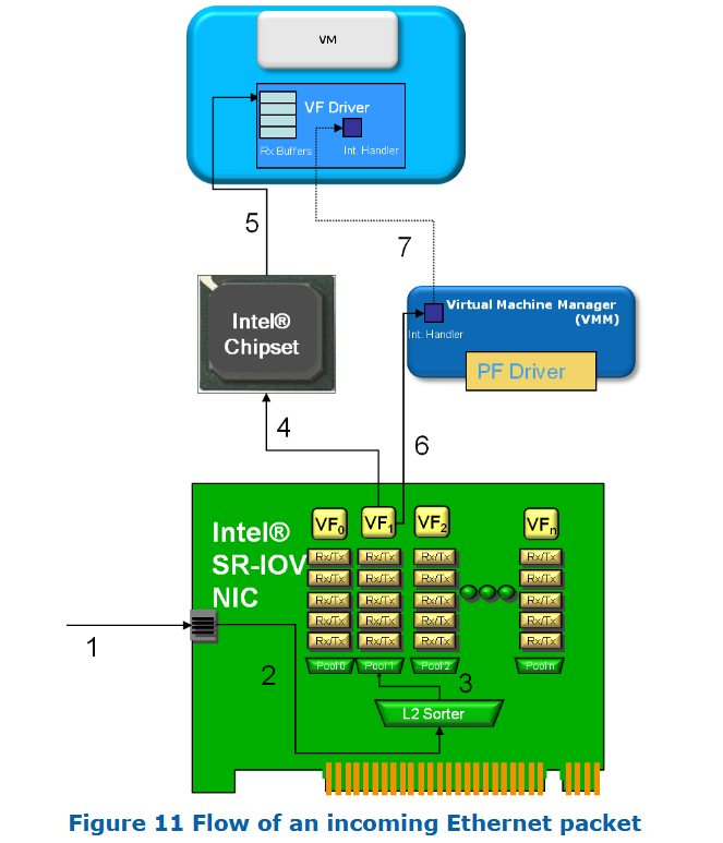
The following is a typical flow for receiving an Ethernet packet and forwarding it to a virtual machine via a VF:
- The packet arrives at the Intel® network adapter.
- The packet is sent to the Layer 2 sorter configured by the main driver.
- After classification, the packet enters the receive queue of the target VF.
- A DMA operation is initiated, whose destination address is determined by the descriptor configured by the VF driver.
- The DMA reaches the chipset. Intel® VT-d configured by the VMM maps the I/O virtual address (IOVA) to the host physical address (HPA), completing the DMA.
- The NIC issues an interrupt, which is captured by the VMM.
- The VMM sends a virtual interrupt to notify the VM that data has arrived.
Summary
The platform must support address translation (such as Intel® VT-d) to allow devices to DMA data directly into VM memory.
The BIOS and VMM must be able to parse the PCI configuration space, especially the SR-IOV VF location mechanism.
The VMM, PF driver, and VF driver must work together to provide the VM with complete PCI space mapping and VF operation capabilities.
Related technologies
PCIe
PCI(Peripheral Component Interconnect)
PCI was once the most widely used interface in personal computers. Almost all motherboard products had this type of slot. Currently, this bus has gradually been replaced by the PCI Express bus. The PCI bus evolved from the ISA (Industry Standard Architecture) bus. It is a synchronous, processor-independent 32-bit or 64-bit local bus. Structurally, PCI is a bus level inserted between the CPU and the original system bus. Specifically, a bridge circuit manages this level and implements the interface between the upper and lower levels to coordinate data transfer.
**Note:**The ISA parallel bus has 8-bit and 16-bit modes, with a clock frequency of 8MHz and an operating frequency of 33MHz/66MHz.
The PCI bus has a tree structure and is independent of the CPU bus, so it can operate in parallel with the CPU bus. PCI devices and PCI bridges can be attached to the PCI bus. Only one PCI master device is allowed on the PCI bus at any given time; all others are PCI slave devices. Read/write operations can only occur between a master and a slave device, and data exchange between slave devices must be relayed through the master device.
**Note:**This does not mean that all read/write operations need to be relayed through the northbridge, because the master and slave attributes of devices on the PCI bus can change. For example, when Ethernet and SCSI need to transfer data, this can be done through a method called Peer-to-Peer. In this case, Ethernet or SCSI acts as the master, and the other devices act as slaves.

A typical 33MHz PCI bus system is shown in the figure above. The processor, through FSB(Front Side Bus, the front-side bus, which in early computer architectureswas the main bus for communication between the processor (CPU) and the northbridge chip, used to connect the CPU and system core components such as the memory controller, graphics card, and PCI bus) to the northbridge. Mounted on the northbridge are the graphics accelerator (graphics card), SDRAM (memory), and the PCI bus. On the PCI bus are mounted the southbridge, Ethernet, SCSI bus (an old minicomputer bus), and several PCI slots. CDs and hard disks are connected to the southbridge via IDE. Audio devices, as well as printers, mice, and keyboards, are also connected to the southbridge. In addition, the southbridge also provides several USB interfaces.
The PCI bus is a shared bus, so it requires a specificarbiter(Arbiter) to determine control of the bus at the current moment. Generally, the arbiter is located in the northbridge, and the arbiter (host) uses a pair of pins REQ#(request) and GNT#(grant) to connect with each slave. As shown in the figure below:

It should be noted that not all devices are capable of becoming an arbiter or initiator.
The initial PCI bus had a clock frequency of 33MHz, and the clock frequency gradually increased with version updates. However, because PCI uses areflected-wave signalingmodel, which means that the higher the clock frequency, the lower the maximum load of the bus.
