
Timeline
Timeline
2025-12-26
init
This article introduces the SoC boot process, including key stages such as BootROM, SPL, and TPL. After the SoC is powered on, the BootROM (primary boot loader) solidified inside the chip takes over the system, completes hardware initialization (such as CPU configuration, disabling the watchdog, initializing clocks and peripherals), and determines the boot device based on the Bootstrap Pin, reading the program from external storage (such as eMMC, Nand, SDCard) into internal SRAM for execution. Since SRAM capacity is limited and u-boot is relatively large, the SPL (Secondary Program Loader) scheme is usually adopted: BootROM first loads SPL into SRAM, and after SPL initializes external SDRAM, it reads the real u-boot from external storage into SDRAM and jumps to execute it. In addition, the article also introduces the division of labor between TPL (Target Program Loader) and SPL: TPL is responsible for chip-level initialization such as DDR configuration, while SPL is responsible for loading trust and u-boot. Finally, taking the Rockchip platform as an example, it explains the TPL/SPL loading and official
BootROM
Generally speaking, SoC manufacturers build a ROM inside the SoC. This ROM is very small and contains the power-on boot code solidified inside (once solidified, it can never be changed; it is built in when the chip is manufactured). This part of the code is called BootROM, also known asprimary boot loader。
After the chip is powered on, the SoC manufacturer’s BootROM takes over the system first. It initializes the hardware and then loads the program into SRAM.
Initialize hardware
- CPU configuration
- Disable the watchdog
- Initialize clocks
- Initialize some peripherals (such as USB Controller, MMC Controller, Nand Controller, etc.);
Load the program into SRAM
A new SoC generally has on the chipsome external storage devices attached(eMMC, Nand, Nor, SDCard, etc.) and memory (SDRAM, DDR, etc.).
Then we need to flash the program for the CPU to execute. Flashing the program is actually to write theexecutable binary filetoexternal storage deviceon (eMMC、Nand、SDetc.). When the system is powered on and boots, it willread them into memory and execute them。
After power-on, the SoC manufacturer’s BootROM takes over the system first. Other executable programs (u-boot, Kernel) are placed (flashed) on external storage. Therefore, in addition to initializing the hardware environment, the BootROM code also needs to go to the external storage and read the next executable program into memory for execution.
Since it is read into memory for execution, can this memory be our onboard DDR?
Theoretically yes, but the DDR controller designed by the SoC manufacturer generally supports many types of DDR devices and provides a compatibility list. How could the SoC manufacturer know exactly which memory is used on the user’s PCB?
Therefore, directly reading the external executable program into DDR is obviously not very friendly. So in general,SoCs typically include a small internal SRAM. ,BootROM reads the external executable program from external storage and places it in SRAM for execution.;
So from which specific memory does BootROM read the binary file?
SoC manufacturers generally support multiple boot modes, such as:
- Read from eMMC.
- Read from SD card.
- Read from NAND flash, etc.
At power-on, it needs to be told what kind of peripheral it should use to read the subsequent boot binary file.
A common design approach is to have a set of bootstrap pins. At power-on, BootROM samples the levels of these IOs to determine which external storage to load the subsequent executable from. For example, with 2 IOs, 2’b00 means boot from NAND, 2’b01 means boot from eMMC, 2’b10 means boot from SD card, etc.
Once BootROM reads these values, it initializes the corresponding peripheral and then reads the code to be executed next. These IOs are usually connected to onboard DIP switches to adjust the chip’s boot mode.
Here, when reading the flashed binary, some details need attention. For example, the SoC manufacturer may tell you that you need to first initialize the SD card with a certain file system and then put the data in for it to work, becausea file system is a way of organizing files, not a raw partition; youIf you place it according to file system A, and the SoC’s BootROM also reads it according to file system A, then they can be consistent.;
SPL
After the chip is powered on, BootROM determines, based on the bootstrap pins, which memory to read the executable binary from into SRAM and execute it. In theory, this binary file could be ouru-boot.binfile; that is, BootROM directly loadsu-boot.bin;
In theory that is the case, but there is a problem: SRAM is expensive. Generally, the on-chip SRAM of an SoC is not very large, typically ranging from 4KB, 8KB, 16KB … up to 256KB. However, the compiled u-boot is very large, several hundred KB, and cannot fit.
What to do if it doesn’t fit? There are two approaches:
- Assume the on-chip SRAM is 4KB,The first 4KB of u-boot implements u-boot’s relocation., i.e.Copy u-boot to SDRAM and run it.;
- Create a smaller boot program,First let BootROM load this small program, and then this small boot loads u-boot.
Approach 1: u-boot relocation
For example, our u-boot is 400KB, SRAM is 4KB, and external SDRAM is 64MB.
If using the first approach, the first 4KB of U-Boot is loaded into SRAM for execution, and U-Boot is truncated, so we need toensure that in the first 4KB of U-Boot code, the on-board SDRAM is initialized, the entire U-Boot is copied to SDRAM, and then jump to SDRAM for execution.;
Approach 2: SPL
For the second approach, we make a small U-Boot, and this U-Boot is calledSPL(Secondary Program Loader), it is very, very small (smaller than SRAM size), itis first loaded into SRAM by BootROM for execution, the main thing SPL does is toinitialize the memory controller, then read the real large U-Boot from external storage into SDRAM, and then jump to the large U-Boot.。
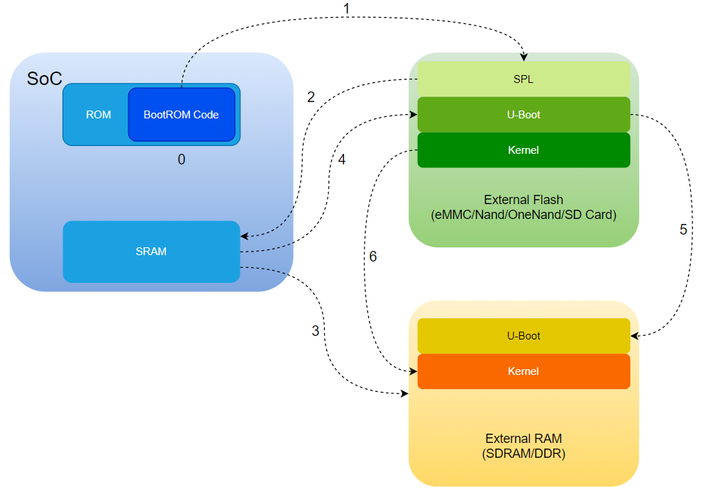
As shown in the figure above:
- After power-on, BootROM starts executing, initializes the clock, disables the watchdog, disables Cache, disables interrupts, etc., determines the boot device according to the Bootstrap Pin, and initializes peripherals;
- Use the peripheral driver to read SPL from storage;
---------------- The above part is the SoC manufacturer’s business, the following is what the user needs to do ----------------
- SPL is read into SRAM for execution. At this point, control has been handed over to our SPL;
- SPL initializes the external SDRAM;
- SPL uses the driver to read U-Boot from external storage and place it into SDRAM;
- Jump to U-Boot in SDRAM for execution;
- Load the kernel;
In actual situations, there are many issues to pay attention to:
- At the compilation stage, does the link address need to be position-independent?
- Is there any overlap between the SPL code and the U-Boot code? If so, does it mean that what SPL has already executed will be executed again after jumping to U-Boot?
- In specific situations, which hardware needs to be configured? How to configure it?
Rockchip Boot Process
For different solutions, Rockchip provides two different bootloader methods, and their steps and generated image files are also completely different.
- TPL/SPL Loading: Use the TPL/SPL officially provided by Rockchip (which is the small U-Boot we mentioned above); this method is completely open source;
- Official firmware loading: Use Rockchip idbLoader, which is composed of
Rockchip rkbin projectofRockchip ddr init binandminiloader bincombined; this method is not open source;
Above we introduced SPL, so what is TPL? In fact, the part of what we mentioned above thatSPL initializes hardware such as SDRAM, and when that part is separated out, it becomes TPL. So let’s summarize:
- TPLYesTarget Program Loader, that is,the chip-level initialization process; at this time, the code is based on the chip platform part. It performs DDR initialization and some other system configurations during the boot process, so that the subsequent SPL can run correctly;
- SPLYesSecondary Program Loader, it reads from the storage devicethe trust (such as ATF/OP-TEE) and U-Boot binary files, and loads them into system memory and runs them, thereby booting the complete operating system;
The difference between TPL and SPL is that their responsibilities are different. TPL is mainly responsible for initializing system hardware, while SPL is responsible for loading and running other software components, such as trust and U-Boot.
In addition, in some special cases, such as encrypted boot or secure boot modes, TPL may also perform other additional tasks.
Boot stages
12345678910111213141516171819202122 | +--------+----------------+----------+-------------+---------+| Boot | Terminology #1 | Actual | Rockchip | Image || stage | | program | Image | Location|| number | | name | Name | (sector)|+--------+----------------+----------+-------------+---------+| 1 | Primary | ROM code | BootROM | || | Program | | | || | Loader | | | || | | | | || 2 | Secondary | U-Boot |idbloader.img| 0x40 | pre-loader| | Program | TPL/SPL | | || | Loader (SPL) | | | || | | | | || 3 | - | U-Boot | u-boot.itb | 0x4000 | including u-boot and atf| | | | uboot.img | | only used with miniloader| | | | | || | | ATF/TEE | trust.img | 0x6000 | only used with miniloader| | | | | || 4 | - | kernel | boot.img | 0x8000 || | | | | || 5 | - | rootfs | rootfs.img | 0x40000 |+--------+----------------+----------+-------------+---------+ |
The boot process involves multiple image files:
- The BootROM in stage one is provided by the SoC vendor;
- Stage two requires providing a
idbloader.img; - Stage three is actually the U-Boot image file; there are two types here: uboot.img (also needs to be paired with trust.img)andu-boot.itb (this is because it already packages ATF inside); besides both containing the original u-boot.bin binary file, these two files also contain some other things, and can be
idbloader.imgrecognized and then loaded; - Stage four and stage five are the kernel image and root file system;
When we discuss booting from eMMC/SD/USB drive/network, they involve different concepts:
- The first stage is always in BootROM; it loads the second stage and may load the third stage (when SPL_BACK_TO_BROM option is enabled);
- Booting from SPI flash means that the second and third stage firmware (SPL and U-Boot only) is in SPI flash, and the fourth/fifth stages are elsewhere;
- Booting from eMMC means that all firmware (including stages 2, 3, 4, and 5) is in eMMC;
- Booting from SD Card means that all firmware (including stages 2, 3, 4, and 5) is in the SD Card;
- Booting from USB drive means that the fourth and fifth stage firmware (excluding SPL and U-Boot) is on the disk, optionally only the fifth stage;
- Booting from Net/TFTP means that the fourth and fifth stage firmware (excluding SPL and U-Boot) is on the network.
idbloader.img
The idbloader.img file is a Rockchip-format preloader that works when the SoC boots. It contains:
- The IDBlock header known by the Rockchip BootROM;
- DDR initialization program, loaded into SRAM by the BootROM and running inside SRAM;
- The next-stage loader, loaded by the BootROM and running on DDR;
u-boot.img
u-boot.bin is the raw binary image generated after compiling the U-Boot source code, and can be directly flashed to the device’s flash memory. u-boot.img, on the other hand, is created bymkimagethe tool adding a header to u-boot.bin; this header may also include some extra data, such as boot parameters and kernel image addresses.
Therefore, byusing u-boot.img instead of u-boot.binthe boot ROM can more easily recognize the U-Boot image and better guide U-Boot to boot correctly on the device.
u-boot.itb
u-boot.itb is actually another variant of u-boot.img, also built with mkimage. In addition to u-boot.dtb and u-boot-nodtb.bin, the two files compiled from the U-Boot source code, it also contains ARM Trusted Firmware such as bl31.elf, bl32.bin, and tee.bin. Among them, bl31.elf is mandatory, while bl32.bin and tee.bin are optional and may be absent.
trust.img
ARM64 SoCs also need to compileATF (ARM Trust Firmware),ATF is mainly responsible for switching the CPU from secure EL3 to EL2 before starting U-Boot.,Then it jumps to U-Boot, and after the kernel starts, it is responsible for starting the other CPUs.。
ATF divides the system boot process comprehensively from the lowest level, placing the secure monitor functionality in BL31. In this way, after the system is fully booted, when an SMC or other interrupt is triggered in the CA or TEE OS, it first traverses the corresponding services registered in BL31 to determine the specific handler. This allows unified management and allocation of all critical SMC or interrupt operations in the system. The block diagram of the entire ATF code boot process is as follows:


As shown in the figure above:
- Boot flow 1 is a typical Rockchip boot flow using the Rockchip miniloader;
- Boot flow 2 is used for most SoCs, using U-Boot TPL for DDR initialization and SPL to load the u-boot.itb file;
Note 1: If loader1 has multiple stages, the program returns to BootROM, and BootROM loads and runs the next stage. For example, if loader1 is TPL and SPL, BootROM first runs TPL, TPL initializes DDR and returns to BootROM, and BootROM then loads and runs SPL.
Note 2: If trust is enabled, in secure mode (EL3 in armv8), loader1 needs to load both trust and U-Boot, then run into trust. Trust initializes in non-secure mode (EL2 in armv8) and runs into U-Boot.
Note 3: For trust (in trust.img or u-boot.itb), armv7 only has a tee.bin with or without TA, while armv8 has bl31.elf and optionally includes bl32.
Note 4: In boot.img, the content can be Linux’s zImage and its dtb, optionally grub.efi, or it can be AOSP boot.img, with ramdisk optional.