
Timeline
Timeline
2025-12-05
- init
This article introduces ARM64 virtualization technology, focusing on the exception levels of the ARMv8 architecture and virtualization implementation. It summarizes the basic concepts, classifications, and application scenarios of virtualization. The article highlights two types of hypervisors, as well as the creation and scheduling mechanisms of vCPUs in CPU virtualization, and elaborates on the role of ARMv8/v9 exception handling in virtualization scenarios. It also covers key technologies of memory virtualization, such as shadow page tables and hardware-assisted stage1/stage2 page tables, along with the four address translation relationships: GVA, GPA, HVA, and HPA. In addition, it introduces three methods of I/O virtualization, including software emulation, device passthrough, and SR-IOV technology, and mentions the development background of hardware-assisted virtualization. Overall, this article systematically reviews the core principles and implementation points of ARM64 virtualization.
Chip manual
- Arm Architecture Reference Manual Armv8, for Armv8-A architecture profile, v8.6
- Content about virtualization: D1.5
- Content about exceptions:
- D1.1 Exception levels
- D1.2 Exception terminology
- D1.10 Exception entry
- D1.11 Exception return
- D1.12 Synchronous exception types, routing and priorities
- D1.13 Asynchronous exception types, routing, masking and priorities
- D13.2.37 ESR_EL2, Exception Syndrome Register(EL2)
- D13.2.138 VBAR_EL2, Vector Base Address Register(EL2)
- D13.2.47 HCR_EL2, Hypervisor Configuration Register
- FAR_EL2 Fault Address Register(EL2)
- D13.2.53 HPFAR_EL2, Hypervisor IPA Fault Address Register
- Content about memory management
- D5.2.3 Controlling address translation stages
- D5.2.6 Overview of the VMSAv8-64 address translation stages
- D5.2.7 The VMSAv8-64 translation table format
- D5.3 VMSAv8-64 translation table format descriptors
- D13.2.61 ID_AA64MMFR0_EL1, AArch64 Memory Model Feature Register 0
- D13.2.146 VTTBR_EL2, Virtualization Translation Table Base Register
- D13.2.145 VTCR_EL2, Virtualization Translation Control Register
- Armv8-A virtualization
- ARM Generic Interrupt Controller Architecture version 2.0, Architecture Specification
Introduction to Virtualization
Virtualization Technology
Virtualization technology, as a resource management technology, can abstract and combine various physical resources of a computer (such as CPU, memory, I/O devices, etc.) and allocate them to multiple virtual machines.
- Platform virtualization(platform virtualization): Virtualization for computers and operating systems, such as KVM, etc.
- Resource virtualization(resource virtualization): Virtualization for specific system resources, including memory, storage, network resources, etc., such as container technology.
- Application virtualization(application virtualization): Includes emulation, simulation, interpretation techniques, etc., such as the Java Virtual Machine.
Virtualization application scenarios
- Desktop virtualization
- Server virtualization
- Embedded virtualization
Important theoretical foundation of virtualization technology
1974: Paper “Formal Requirements for Virtualizable Third Generation Architectures”
Three necessary elements for implementing virtualization:
- Resource control. The VMM must be able to manage all system resources.
- Equivalence. The guest’s runtime behavior is consistent with that on bare metal.
- Efficiency. Programs running on the guest are not interfered with by the VMM.
The x86 architecture encountered some challenges in implementing virtualization, particularly in failing to meet the second condition above. Computer architectures contain two types of instructions.
- Sensitive instructions: Instructions that operate on certain privileged resources, such as instructions that access or modify virtual machine mode or machine state.
- Privileged instructions: Instructions with special privileges. These instructions are only used by the operating system or other system software, and are generally not directly provided to users.
Hardware-assisted virtualization technology
- In 2005, Intel began introducing hardware virtualization technology into CPUs, called VT (virtualization technology).
- The basic idea of VT is to create containers that can run virtual machines. In a VT-enabled CPU, there are two operating modes: root (VMX root) mode and non-root (VMX non-root) mode. Both modes support four privilege levels, Ring 0 through Ring 3, so both the hypervisor and virtual machines can freely choose the privilege level at which they wish to run.


Full virtualization and paravirtualization

Currently, hardware-assisted virtualization is mainly used, and these two technologies are no longer widely used.
Classification of virtual machines
Hypervisor: Hypervisor, also called VMM (Virtual Machine Manager), is located between computer hardware and virtual machines, and is responsible for managing and allocating computer resources to each virtual machine.
- Type 1: The first type of hypervisor is like a small operating system, whose purpose is to manage all virtual machines. Common virtualization software includes Xen, ACRN, etc.
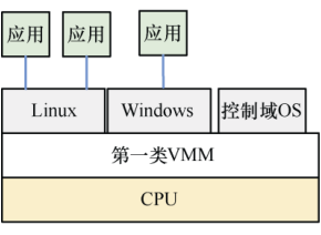
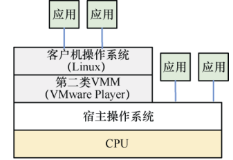
Type1 Hypervisor - Type 2: The second type of hypervisor relies on operating systems such as Windows and Linux to allocate, manage, and schedule resources. Common virtualization software includes VMware Workstation, KVM, and VirtualBox, etc.
Memory virtualization
Software emulation: Shadow Page Table
- Low efficiency

Hardware memory virtualization technology:
- Intel: Extended Page Table (EPT) technology
- ARM: stage1 & stage2 page tables
Four types of addresses used in virtualization
- GVA (Guest Virtual Address): Guest virtual address.
- GPA (Guest Physical Address): Guest physical address.
- HVA (Host Virtual Address): Host virtual address.
- HPA (Host Physical Address): Host physical address.
I/O virtualization
Software-emulated devicesFor example, with disks, the hypervisor can create a file or a region on the physical disk to emulate a virtual disk and pass it to the guest.
Device pass-through(Device Pass Through). The hypervisor directly assigns a physical device to a specific virtual machine.
SR-IOVSingle Root I/O Virtualization (SR-IOV) technology
CPU virtualization
vCPU and VM concepts

- ARMv8/v9 CPU virtualization technology is built on different exception levels.

Creating multiple vCPUs
A physical CPU can create multiple vCPUs, leveraging the OS’s multi-process/multi-thread mechanism.

A physical CPU can run multiple processes/threads, and the hypervisor can schedule them to run in a time-sharing manner. When the hypervisor switches from EL2 to the EL1/EL0 execution context, it creates a running opportunity for a vCPU.
ARMv8/v9 exception handling
- Non-virtualized scenario: Exception handling is concentrated at EL1, such as exception vector tables, exception handling, interrupt handling, system calls, etc.

Virtualized scenario:

Virtualized scenario - For the hypervisor: It needs to handle exceptions from the hypervisor itself, exceptions from VMs (such as HVC), interrupts from VMs, and so on.
- For the VM: The VM itself also needs to handle exceptions and system calls from within the VM (the Guest OS handles app exceptions and system calls).
Hypervisor enters VM

- Set HCR_EL2.RW so the CPU runs in AArch64
- Temporarily disable the vCPU’s MMU (optional)
- Set SPSR_EL2 so that after the ERET instruction executes, the CPU jumps to EL1
- Set the ELR_EL2 register to jump to the vm_entry function after executing the ERET instruction, perform the processor mode transition, and make the CPU enter EL1
- Set the SP_EL1 stack so the vCPU points to a new stack space
123456789101112131415161718192021222324 | .global jump_to_vmjump_to_vm: /* Set EL1 execution state to AArch64 */ ldr x0, =HCR_HOST_NVHE_FLAGS //NVHE(Non-Virtualized Host Environment) msr hcr_el2, x0 /* Disable the MMU for EL1 */ ldr x0, =SCTLR_VALUE_MMU_DISABLED msr sctlr_el1, x0 /* Set SPSR_EL2 to enter EL1h (64-bit) on return*/ ldr x0, =SPSR_EL1 msr spsr_el2, x0 /* Set the VM entry address (ELR_EL2)*/ adr x0, vm_entry msr elr_el2, x0 /* Set the VM stack pointer (SP_EL1)*/ adr x2, vm_sp add x2, x2, #4096 msr sp_el1, x2 eret |
Exit from the VM to the Hypervisor
- The VM’s guest OS actively invokes HVC
- An exception occurred in the VM (cannot be handled in EL1, e.g., a Stage 2 page fault)
- A hardware interrupt occurred
HVC system call
SVC system call: an app running at EL0 requests to enter the OS at EL1.
HVC system call: a VM running at EL1 requests to enter the hypervisor at EL2.
SMC system call: software running in the hypervisor or VM requests to enter the EL3 secure firmware (Secure Monitor).

1234567891011121314 |
Follows the ARM64 standard function call convention (AAPCS64):
x0: Return value / first parameterx1,x2: Parametersx8: HVC function number (i.e.which)
Exception Syndrome Information Register ESR_EL2

The ESR_EL2 register contains a total of 4 fields (domains), where:
- Bits 32~63 (RES0) are reserved bits.
- Bit 26~31,EC(Exception Class), this field indicates the type of exception that occurred and is also used to index the ISS field.
- Bit 25,IL(Instruction Length for synchronous exceptions), indicates the instruction length of a synchronous exception.
- Bit 0~24,ISS(Instruction Specific Syndrome), specific exception instruction encoding. This exception instruction encoding table depends on the exception type; different exception types have different encoding formats.
Exception Class
- Range division:
0x00–0x2C: reserved for Synchronous exception0x2D–0x3F: reserved for Synchronous or asynchronous exception
- Reserved (Reserved):
0x02,0x0A–0x0B,0x0F,0x10,0x14,0x1B,0x1D–0x1F,0x23,0x27,0x29–0x2E,0x36–0x37,0x39,0x3B,0x3D–0x3F- Programming these values will cause CONSTRAINED UNPREDICTABLE behavior
| EC value (binary) | EC value (hexadecimal) | Exception type description | Whether it depends on AArch32 / feature |
|---|---|---|---|
0b000000 | 0x00 | Unknown reason(unknown reason) | General |
0b000001 | 0x01 | Trapped WFI/WFE(trapped WFI or WFE instruction) | General |
0b000011 | 0x03 | MCR/MRC (coproc=0b1111)(AArch32 coprocessor access) | Requires AArch32 support |
0b000100 | 0x04 | MCRR/MRRC (coproc=0b1111) | Requires AArch32 support |
0b000101 | 0x05 | MCR/MRC (coproc=0b1110) | Requires AArch32 support |
0b000110 | 0x06 | LDC/STC(Debug data transfer instruction) | Requires AArch32 support |
0b000111 | 0x07 | Trapped FP/SVE disabled by CPACR/CPTx.FPEN(Floating-point/SVE access disabled) | General (requires FP/SVE) |
0b001000 | 0x08 | VMRS(ID group trap) | Requires AArch32 support |
0b001001 | 0x09 | Pointer Authentication instruction disabled(HCR_EL2.API=0, etc.) | Requires ARMv8.3-PAuth |
0b001100 | 0x0C | MRRC (coproc=0b1110) | Requires AArch32 support |
0b001101 | 0x0D | Branch Target Exception (BTI) | Requires ARMv8.5-BTI |
0b001110 | 0x0E | Illegal Execution state(Illegal execution state) or PC alignment error | General |
0b010001 | 0x11 | SVC in AArch32(Reported to EL2 only when HCR_EL2.TGE=1) | Requires AArch32 support |
0b010010 | 0x12 | HVC in AArch32(HVC not disabled) | Requires AArch32 support |
0b010011 | 0x13 | SMC in AArch32(Reported to EL2 only when HCR_EL2.TSC=1) | Requires AArch32 support |
0b010101 | 0x15 | SVC in AArch64 | Requires AArch64 support |
0b010110 | 0x16 | HVC in AArch64(HVC not disabled) | Requires AArch64 support |
0b010111 | 0x17 | SMC in AArch64(Reported to EL2 only when HCR_EL2.TSC=1) | Requires AArch64 support |
0b011000 | 0x18 | Trapped MSR/MRS/System instruction(AArch64 system register access) | Requires AArch64 support |
0b011001 | 0x19 | Trapped SVE disabled by CPACR/CPTx.ZEN | Requires SVE support |
0b011010 | 0x1A | Trapped ERET/ERETAA/ERETAB | Requires ARMv8.3-PAuth + NV |
0b011100 | 0x1C | Pointer Authentication failure | Requires ARMv8.3-FPAC |
0b100000 | 0x20 | Instruction Abort from lower EL(Instruction fetch exception from a lower exception level) | General |
0b100001 | 0x21 | Instruction Abort at same EL(Instruction fetch exception from the same exception level) | General |
0b100010 | 0x22 | PC alignment fault(Program counter misaligned) | General |
0b100100 | 0x24 | Data Abort from lower EL(Data access exception from a lower exception level) | General |
0b100101 | 0x25 | Data Abort at same EL(Including nested virtualization VNCR-related) | General |
0b100110 | 0x26 | SP alignment fault(Stack pointer misaligned) | General |
0b101000 | 0x28 | Trapped FP exception (AArch32) | Requires AArch32 + FP trap support |
0b101100 | 0x2C | Trapped FP exception (AArch64) | Requires AArch64 + FP trap support |
0b101111 | 0x2F | SError interrupt(Synchronous external error interrupt) | General |
0b110000 | 0x30 | Breakpoint from lower EL | General |
0b110001 | 0x31 | Breakpoint at same EL | General |
0b110010 | 0x32 | Software Step from lower EL | General |
0b110011 | 0x33 | Software Step at same EL | General |
0b110100 | 0x34 | Watchpoint from lower EL | General |
0b110101 | 0x35 | Watchpoint at same EL(including VNCR) | General |
0b111000 | 0x38 | BKPT instruction (AArch32) | Requires AArch32 support |
0b111010 | 0x3A | Vector Catch (AArch32) | Requires AArch32 support |
0b111100 | 0x3C | BRK instruction (AArch64) | Requires AArch64 support |
1234 | .global hvc_callhvc_call: hvc 0x0 ret |
Exit from VM to Hypervisor, hvc system call, function number 10 saved to x0
1 | hvc_call(10); |
Trigger synchronous exception from Lower EL using AArch64, the exception vector table is below
12345 | / * Lower EL using AArch64 */vtentry __do_vcpu_exitvtentry __invalidvtentry __invalidvtentry __invalid |
Jump to the exception vector table after triggering the exception__do_vcpu_exitfunction
12345678910111213141516 | _do_vcpu_exit: vm_exit 1 mrs x25, esr_el2 // Read ESR_EL2 register (Exception Syndrome Register), save to x25 lsr x24, x25, #ESR_ELX_EC_SHIFT // Right shift to get the EC field ([31:26]), i.e., Exception Class cmp x24, #ESR_ELX_EC_HVC64 // Compare whether it is an HVC64 exception (EC == 0b010110) b.eq vm_hvc // If equal, jump to vm_hvc to handle HVC mov x0, sp // Set parameter: x0 = current stack pointer mov x1, #BAD_SYNC // Set error code: BAD_SYNC (indicating synchronous exception) mrs x2, esr_el2 // Read ESR_EL2 again as context information bl bad_mode // Jump to bad_mode to handle unknown/illegal exceptionvm_hvc: mov x0, sp // Set parameter: x0 = stack pointer bl vm_hvc_handler // Call the HVC handler function vm_entry 1 // Return to continue running the virtual machine (enter VM) |
vm_exitandvm_entryMacro implementation:
123456789101112131415161718192021222324252627282930313233343536373839404142434445464748495051525354555657585960616263646566676869707172737475767778798081828384858687888990919293949596979899100101102103104 | #define S_FRAME_SIZE 272 /* sizeof(struct pt_regs) // */#define S_X0 0 /* offsetof(struct pt_regs, regs[0]) // */#define S_X1 8 /* offsetof(struct pt_regs, regs[1]) // */#define S_X2 16 /* offsetof(struct pt_regs, regs[2]) // */#define S_X3 24 /* offsetof(struct pt_regs, regs[3]) // */#define S_X4 32 /* offsetof(struct pt_regs, regs[4]) // */#define S_X5 40 /* offsetof(struct pt_regs, regs[5]) // */#define S_X6 48 /* offsetof(struct pt_regs, regs[6]) // */#define S_X7 56 /* offsetof(struct pt_regs, regs[7]) // */#define S_X8 64 /* offsetof(struct pt_regs, regs[8]) // */#define S_X10 80 /* offsetof(struct pt_regs, regs[10]) // */#define S_X12 96 /* offsetof(struct pt_regs, regs[12]) // */#define S_X14 112 /* offsetof(struct pt_regs, regs[14]) // */#define S_X16 128 /* offsetof(struct pt_regs, regs[16]) // */#define S_X18 144 /* offsetof(struct pt_regs, regs[18]) // */#define S_X20 160 /* offsetof(struct pt_regs, regs[20]) // */#define S_X22 176 /* offsetof(struct pt_regs, regs[22]) // */#define S_X24 192 /* offsetof(struct pt_regs, regs[24]) // */#define S_X26 208 /* offsetof(struct pt_regs, regs[26]) // */#define S_X28 224 /* offsetof(struct pt_regs, regs[28]) // */#define S_FP 232 /* offsetof(struct pt_regs, regs[29]) // */#define S_LR 240 /* offsetof(struct pt_regs, regs[30]) // */#define S_SP 248 /* offsetof(struct pt_regs, sp) // */#define S_PC 256 /* offsetof(struct pt_regs, pc) // */#define S_PSTATE 264 /* offsetof(struct pt_regs, pstate) // */#define BAD_SYNC 0#define BAD_IRQ 1#define BAD_FIQ 2#define BAD_ERROR 3.macro kernel_exit el // load ELR, SPSR, restore the PC and PSTATE values ldp x21, x22, [sp, #S_PC] \el == 1 ldr x23, [sp, #S_SP] msr sp_el1, x23 msr elr_el2, x21 msr spsr_el2, x22 ldp x0, x1, [sp, #16 * 0] ldp x2, x3, [sp, #16 * 1] ldp x4, x5, [sp, #16 * 2] ldp x6, x7, [sp, #16 * 3] ldp x8, x9, [sp, #16 * 4] ldp x10, x11, [sp, #16 * 5] ldp x12, x13, [sp, #16 * 6] ldp x14, x15, [sp, #16 * 7] ldp x16, x17, [sp, #16 * 8] ldp x18, x19, [sp, #16 * 9] ldp x20, x21, [sp, #16 * 10] ldp x22, x23, [sp, #16 * 11] ldp x24, x25, [sp, #16 * 12] ldp x26, x27, [sp, #16 * 13] ldp x28, x29, [sp, #16 * 14] ldr lr, [sp, #S_LR] // restore sp add sp, sp, #S_FRAME_SIZE eret.endm.macro kernel_entry el sub sp, sp, #S_FRAME_SIZE stp x0, x1, [sp, #16 * 0] stp x2, x3, [sp, #16 * 1] stp x4, x5, [sp, #16 * 2] stp x6, x7, [sp, #16 * 3] stp x8, x9, [sp, #16 * 4] stp x10, x11, [sp, #16 * 5] stp x12, x13, [sp, #16 * 6] stp x14, x15, [sp, #16 * 7] stp x16, x17, [sp, #16 * 8] stp x18, x19, [sp, #16 * 9] stp x20, x21, [sp, #16 * 10] stp x22, x23, [sp, #16 * 11] stp x24, x25, [sp, #16 * 12] stp x26, x27, [sp, #16 * 13] stp x28, x29, [sp, #16 * 14] \el == 1 msr x21, sp_el1 // x21 points to the stack top add x21, sp, #S_FRAME_SIZE mrs x22, elr_el2 mrs x23, spsr_el2 // save lr and sp to sp+#S_LR(pt_regs->regs[30]) and sp+#S_LR+8(pt_the location of regs->sp) stp lr, x21, [sp, #S_LR] // save ELR_EL2 and SPSR_EL2 to sp+#S_PC(pt_regs->pc) and sp+#S_PC+8(pt_regs->pstate) // here ELR_EL2 saves the PC, because when entering an exception, the hardware automatically saves the PC and PSTATE before the exception to ELR._ELn // and SPSR_ELn (The Saved Program Status Register) stp x22, x23, [sp, #S_PC].endm |
vm_hvc_handlerImplementation
1234 | void vm_hvc_handler(struct pt_regs *regs){ unsigned int el = read_sysreg(CurrentEL)>>2; printk("%s jump into hypervisor(el=%d), hvccall num: %d\n", __func__, el, regs->regs[0]);} |
Memory virtualization
ARM64 page table mapping

There is only one stage of address mapping, Stage 1, which converts virtual addresses to physical addresses.
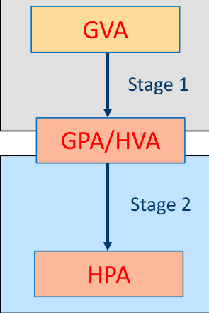
Two-stage address mapping:
- Stage 1: GVA -> GPA inside the VM
- Stage 2: HVA to HPA in the hypervisor
Each stage of mapping goes through a 3-level or 4-level page table.
From a system perspective
Two-stage address translation in virtualization
- VA (Virtual Address) -> IPA (Intermediate Physical Address)(ARM manual terminology)
- IPA -> PA(PA: Physical Address)

The hypervisor itself also has memory access requirements, using another set of page tables (under NVHE, TTBR0_EL1, under VHE it is TTBR0_EL2), meaning there are three sets of page tables in total
2 Stage page table translation
- 2 Stage requires more memory consumption
- Translation of VA->IPA->PA: in the worst case, it requires more memory access processes (each level of page table lookup may require memory access, the exact number depends on TLB hit conditions and the number of page table levels).
- Both Stage 1 and Stage 2 can be cached in the TLB.

Stage 1 page table mapping
Non-virtualization: VA -> PA
Virtualization: VA -> IPA
Major factors affecting page table mapping
- Input address size: determined by TCR_ELx.TxSZ, specifies the range of VA, and also determines how many levels of page tables are used. Usually 48 bits.
- Output address size: determined by ID_AA64MMFR0_EL1.PARange, the maximum physical memory supported by the system, filled into TCR_ELx.{I}PS.
- Page granularity: specified by TG0 and TG1 in TCR_ELx.
Stage 2 page table mapping
- Virtualization: IPA(GPA) -> PA
Major factors affecting page table mapping
- Input address size: the maximum value of IPA is constrained by the system PA, and PA is determined by ID_AA64MMFR0_Determined by EL1.PARange.
The GPA in a VM cannot exceed the physical memory size.
- Output address size: determined by ID_AA64MMFR0_EL1.PARange, the maximum physical memory supported by the system, filled into VTCR_EL2.PS.
- Page granularity: specified by TG0 in VTCR_EL2
Stage 2 page table mapping supports 4-level or 3-level page table mapping
- Input address size (PA size)
- Page table granularity (4KB? 16KB? 64KB?)
- At which level does the page table walk start? (VTCR_EL2.SL0)
How to know the PA?
Taking the Cortex-A72 processor as an example, referring to the Cortex-A72 Technical Reference Manual, we can see thatThe Physical Address range supports up to 44 bits,16TB。
Newer IPs such as Cortex-A77, A78, X2, etc., support a maximum PA of 40 bits, 1TB.

T0SZ is 64 -Support PA size
Taking 4KB page granularity as an example
- When PA is 44 bits, 4-level page table mapping is supported
- When PA is 42 bits, 40 bits, 36 bits, or 32 bits, 3-level page table mapping is supported
When PA is 42 bits and 40 bits, S2 concatenated page tables can be used to compress a 4-level page table into 3 levels
S2 concatenated page table
Taking 40 bits + 4KB as an example

An extra bit 39 is used to index two page table entries in the L0 page table, each pointing to an L1 page table

After using concatenated page tables, the two L1 page tables pointed to by the two page table entries of the original L0 page table are concatenated together, making the L1 page table equivalent to twice its original size.
- The L1 index range also becomes twice the original
- The MMU starts indexing directly from the L1 page table, thus turning a 4-level page table into a 3-level page table
Advantage: It can avoid the overhead caused by an extra level of translation.
- The maximum number of concatenated tables supported is 16.
- The VTCR_EL2.SL0 field is used to indicate: at which level of page table to start indexing

- IA: Input Address, indicating the use of 40~48-bit virtual addresses
- The first row, Tables, indicates the number of tables that can be concatenated, with a maximum of 16. 1 means no concatenation, 2 means two page tables concatenated.
- The first column, Initial lookup level (SL0 value), indicates which level of page table the hardware starts traversing from, by setting VTCR_EL2.SL0.

Taking 43 bits + 4KB page granularity as an example, if using S2 concatenated page tables, the L1 page table will be formed by concatenating 16 tables.
S2 page table attributes
S2 page table attributes are slightly different from S1 page table attributes.

MemAttr


S2AP attribute


Registers related to S2 page tables
Page table base address register:VTTBR_EL2
S2 page table translation control register:VTCR_EL2

VTCR_EL2 PS indicates the maximum physical address.
TG0 indicates page granularity: 4KB, 16KB, 64KB.
SL0 indicates which level of page table the MMU starts querying from.
T0SZ is used to specify the IPA range, and this value is constrained by PA. It indicates that the IPA range is
Hypervisor configuration register:HCR_EL2。
- VM field: enable S2 page table mapping
Experiment 3: Create S2 mapping with 4-level page table
Experiment objective: Understand the S2 page table of the ARM64 architecture.
Experiment requirements: Based on Experiment 2, enable the HCR_EL2_VM field, enable the S2 MMU page table, what will happen? Please analyze.
This experiment uses “IPA 44Bits + 4KB page granularity + 4-level mapping” to create the S2 page table. After enabling the S2 page table mapping, when jumping to the VM, executing the first instruction will trigger a page fault exception because no mapping has been established for the first instruction. This experiment uses page fault exception handling to build the S2 page table page by page.
TODO
Experiment 4: Create an S2 concatenated page table with 43-bit IPA
Experiment objective: Understand the S2 concatenated page table of the ARM64 architecture.
Experiment requirements: Based on the previous experiment, this experiment creates an S2 concatenated page table with IPA of 43 bits and page granularity of 4KB. Draw a structural diagram of the mapping.
TODO
Experiment 5: Create an S2 concatenated page table with 40-bit IPA
Experiment objective: Understand the S2 concatenated page table of the ARM64 architecture.
Experiment requirements: Based on the previous experiment, this experiment creates an S2 concatenated page table with IPA of 40 bits and page granularity of 4KB. Draw a structural diagram of the mapping.
Experiment 6: Create two-stage address mapping in a virtual machine
Experiment objective: Understand the 2-stage page table mapping of the ARM64 architecture.
- Establish the second-stage address mapping, i.e., the mapping from GPA to HPA, using identity mapping.
- Establish the first-stage address mapping, i.e., the mapping from GVA to GPA, using non-identity mapping.
Experiment requirements:
- Allocate a page in the Hypervisor. Since the Hypervisor uses identity mapping, gpa = hpa.
- Write a value into this gpa, for example 0x12345678.
- When switching to the VM, pass this GPA to the VM.
- In the VM, create a mapping from GVA to GPA, assuming the GVA address is 0x80000000.
- Then read the value at the gva address in the VM, and check whether it is 0x12345678?
Please draw a diagram of all mappings in this system, including those inside the VM and the Hypervisor.
TODO


IO device virtualization
Three mainstream methods
Full software virtualization: Uses the “trap & emulate” approach to fully emulate device behavior.
Paravirtualization: Uses efficient front-end drivers and back-end drivers to reduce VM trap events and improve I/O device virtualization performance, such as VirtIO technology.
Hardware-assisted virtualization: Hardware direct passthrough, IOMMU, and SR-IOV (Single Root I/O Virtualization)
Flow of emulating MMIO register access (trap & emulate)

Decode the triggering instruction
- VM accesses MMIO, triggering a “Data Abort from a lower Exception level” exception.
- No need to manually decode the exception instruction encoding; the hardware has already decoded it. Just read the ISS field of ESR_EL2:

- ISV: bit 24, indicating that the exception instruction decoding contained in ISS[23:0] is valid.
- SAS: The size of the memory access when the exception occurred.
- SSE: Whether the data needs sign extension.
- SRT: Destination register Rt
- SF: Whether it is a 32-bit or 64-bit load/store instruction
- AR: Whether the instruction includes acquire/release barrier semantics
- VNCR: Whether the access is from nested virtualization
- SET: Synchronous error type.
- FnV: Whether the FAR register is valid.
- WnR: Whether the exception was triggered by a read or write operation
Flow of emulating UART MMIO register read

Flow of emulating UART MMIO register write

Experiment 7: Simulating a serial port device in a hypervisor
Experiment objective: Use full software virtualization to simulate a serial port device
Experiment requirements: Implement a serial port driver in the GuestOS, and enable the GuestOS to print output from the serial port
TODO
Timer virtualization
- System counter: Provides a system-wide shared, fixed-frequency system counter.
- The system counter is broadcast to all cores.
- The CNTPCT_EL0 register returns the value of the system counter.
- The CNTFRQ_EL0 register is used to set the frequency corresponding to the system counter.
- Each CPU core has a set of timers.

generic timer
Each ARMv8/v9 CPU core has a set of generic timers.
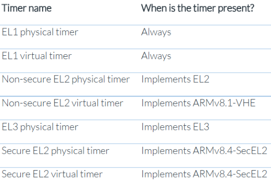
Taking Cortex-A72 as an example, the following is a functional description of the Generic Timer:
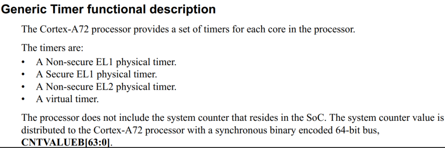
Difference between physical timers and virtual timers
The virtual counter canmeasure the passage of time on a virtual machine。
The passage of time on a virtual machine != the passage of time on a real physical machine

Assume two vCPUs run alternately, each vCPU runs for 1ms

If vCPU0 sets a timer at T=0 to trigger an interrupt after 3ms, has the interrupt been triggered?
Physical time vs virtual time: Physical time refers to wall-clock time, i.e., the actual elapsed time. Virtual time refers to the time experienced by the virtual processor (vCPU).
At physical time 4 ms, vCPU0 has only run for 2 ms (virtual time). According to the passage of virtual time, the time set by vCPU0’s comparator has not yet reached 3 ms, so the interrupt will not be triggered at this point.
Virtual counter = physical counter - offset
CNTVCT_EL0 (virtual counter) = CNTPCT_EL0 (physical counter) - CNTVOFF_EL2 (virtual offset)
Method 1 for calculating virtual time in a VM

Virtual time offset (i.e., the time the vCPU was not scheduled to run)
where Time_sched_in is the time when the vCPU is scheduled to run, Time_sched_out is the time when the vCPU is scheduled to be suspended.
Method 1: The hypervisor updates the CNTVOFF_EL2 register each time the vCPU is scheduled to run.
Method 2 for calculating virtual time in a VM

Method 2:
- Set the virtual offset to a constant value: virtual counter = physical counter - virtual offset
- When the vCPU is scheduled out, the hypervisor disables the virtual timer interrupt, so the vCPU’s jiffies temporarily stop incrementing.
- When the vCPU is scheduled to run, the hypervisor enables the virtual timer interrupt, and the vCPU’s jiffies resume incrementing.
Two ways for the timer to trigger an interrupt
- Using the TimeValue method: assign an initial value to the timer and let it count down. When it decrements to 0, an interrupt is triggered, and the timer is reassigned a value in the interrupt handler.

- Using the CmpValue method: assign a compare value CValue to the timer. When the timer increases to CValue, an interrupt is triggered.

Experiment 8: Enable the hypervisor (EL2) physical timer
Experiment objective: Become familiar with the usage of the generic timer in the arm64 architecture.
Experiment requirements: Enable the EL2 physical timer in BenOS.
TODO
Experiment 9: Enable the virtual timer in the VM
Experiment objective: Become familiar with the usage of the generic timer in the arm64 architecture.
Experiment requirements: Enable the virtual timer in BenOS. In this experiment, the prints in the Guest OS’s timer interrupt handler cannot be seen, because the virtual timer interrupt in the VM is routed to the hypervisor at EL2 for handling, and then injected into the VM. This process requires implementing GIC interrupt virtualization.
TODO
Interrupt virtualization
Interrupt handling routing

For exceptions and interrupts, they can be routed to EL1, EL2, or EL3 for handling, requiring configuration of HCR and SCR related registers.
The HCR_EL2 register is the hypervisor configuration register, which contains the following fields related to exception handling routing.


Virtual interrupt
- There are two ways to send virtual interrupts to a vCPU
- Use system registers (the VI and VF fields in HCR_EL2) to configure vIRQ and vFIQ
- Use GICv2 and GICv3 controllers
- Using vIRQ and vFIQ requires emulating the interrupt controller in the hypervisor
- Inefficient, trapping and emulating
- The GIC interrupt controller supports vCPUs and does not require software emulation
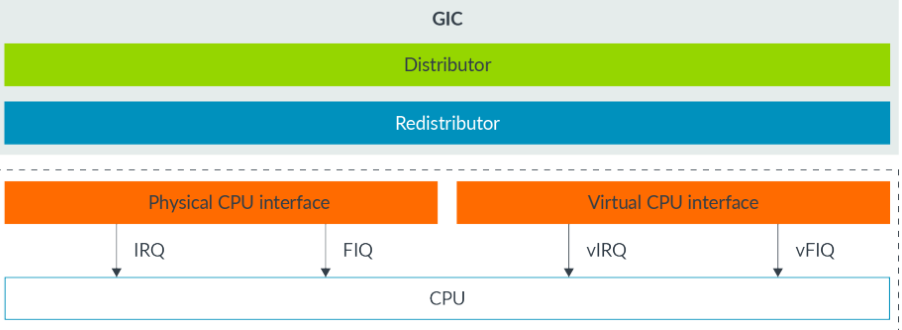
GICv2 interrupt controller

The Distributor registers (GICD_) Contains interrupt settings and configuration
The CPU Interface registers (GICC_) Contains CPU-related special settings
GIC interrupt types
- SGI: Software Generated Interrupt, a software-generated interrupt used to send interrupt signals to other CPU cores.
- PPI: Private Peripheral Interrupt, a private peripheral interrupt that is unique to a specific CPU.
- SPI: Shared Peripheral Interrupt, a shared peripheral interrupt that all CPUs can access.
- LPI: Locality-specific Peripheral Interrupt, a new interrupt type added in GICv3. It is a message-based interrupt type.

Note: Interrupt numbers 1020 to 1023 are reserved.

GICv2 registers
GICv2 registers are divided into two groups:
- D: Represents the Distributor registers
- C: Represents the CPU interface registers
Some registers are described by interrupt number, for example, using certain bits to describe the attributes of an interrupt number. The same register can have multiple instances (denoted by n).
For exampleGICD_ISENABLERnregister, which is used to enable a certain interrupt number. ‘n’ indicates that it has n such registers.

It can be seen that this register ranges from 0x100 to 0x17C, and these offsets correspond to different instances of the same register.

Each bit in the register represents the enable of an interrupt number.

- ARM Core interrupts:
- Core n HP tiemr IRQ
- Core n V timer IRQ
- Legacy FIQn
- Core n PS timer IRQ
- Core n PNS timer IRQ (PPI ID 30)
- Legacy IRQn
- ARM local interrupts
- ARM Mailbox IRQs
- Core 0 PMU IRQ
- Core 1 PMU IRQ
- Core 2 PMU IRQ
- Core 3 PMU IRQ
- AXIERR IRQ
- Local timer IRQ
- 16 ARM peripheral interrupts
- 64 VC peripheral interrupts
- 51 PCIe-related peripheral interrupts
Accessing GIC-400 registers
- Base address of GIC-400 on Raspberry Pi 4B

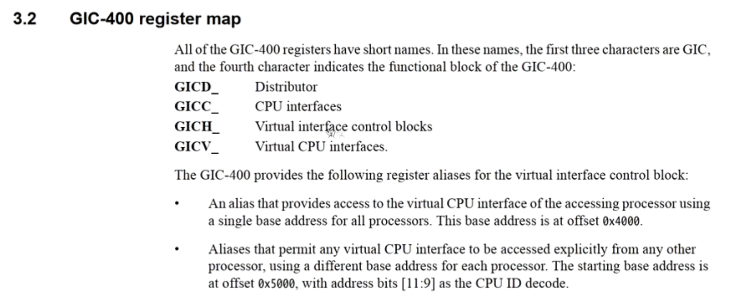
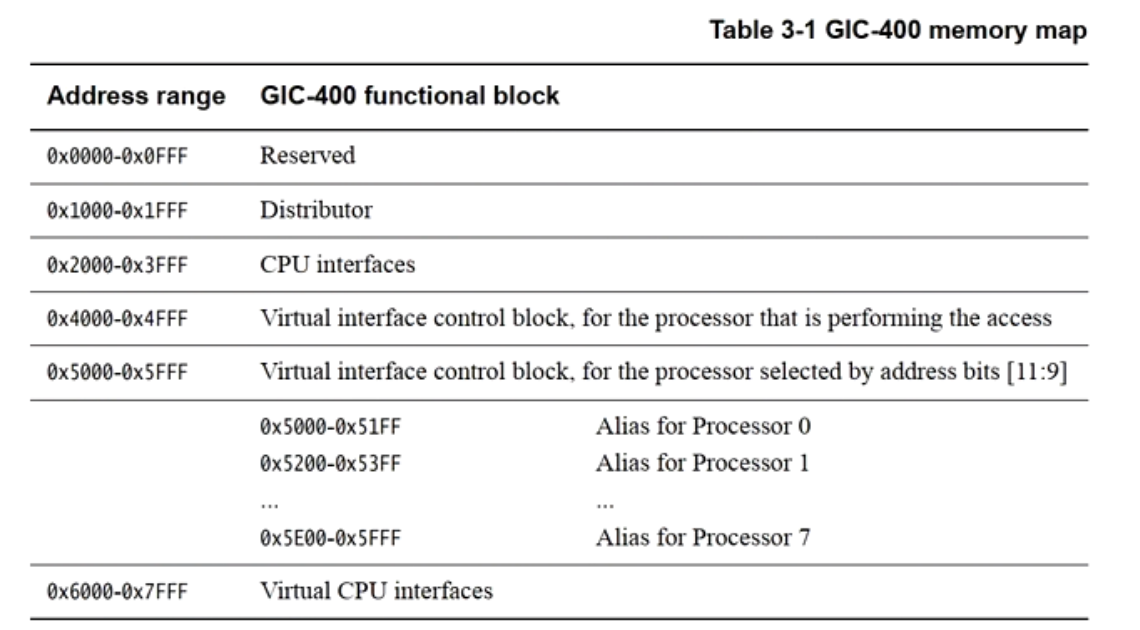
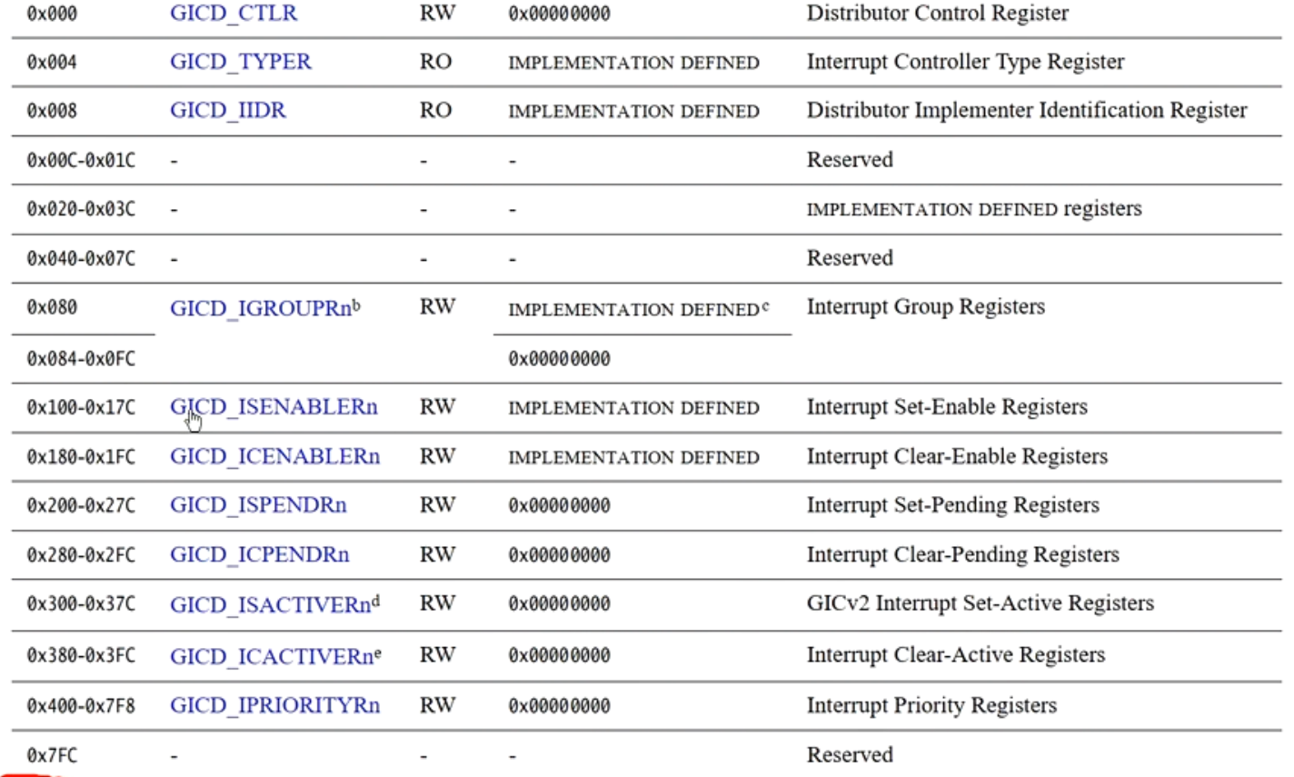
Access: Raspberry Pi GIC-400’sbase address + GIC-400 memory map offset + register offset
Virtualization support on GIC v2
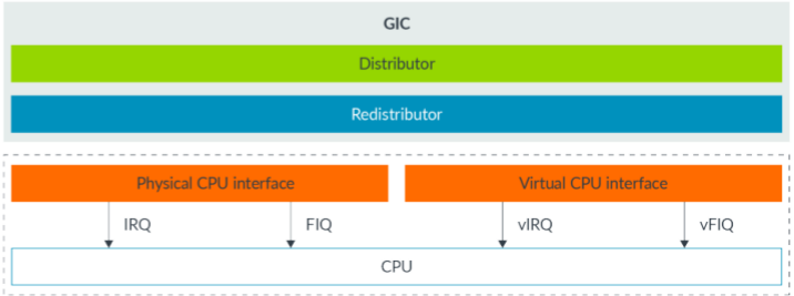
To support virtualization, GIC v2:
- Addedvirtual CPU interface, sends vIRQ/vFIQ to the vCPU.
- AddedGIC virtual interface control registers。
- AddedGIC virtual CPU interface registers
There is only one Distributor, and the hypervisor needs to emulate a vDistributor for the VM.

GIC v2 interrupt virtualization flow
- Ensure all interrupts are routed to the EL2 hypervisor for handling.。
- The hypervisor emulates a vDistributor for the VM to use, that is, when the Guest OS accesses the GIC distributor’s MMIO registers, it traps to the hypervisor.。
- Establish a mapping in the hypervisor, that is, the MMIO region of the GIC CPU interface accessed by the Guest OS is mapped to the GIC virtual CPU interface.。
- When the hypervisor receives a physical interrupt, it must decide whether the interrupt is handled by the hypervisor or injected into the VM for handling.。
- If an interrupt needs to be injected into the VM, update the GICH_LRn register to fill in the interrupt-related information. When the CPU returns to the vCPU, the interrupt injection is complete.。
- When the VM is running, reading the GICV_IAR register can obtain the virtual interrupt number.

The peripheral interrupt flow is as follows:
- It enters the Distributor hardware unit in the GIC controller, and then is dispatched to a physical CPU interface.
- The CPU will respond to this interrupt.
- This interrupt will be routed to EL2. The hypervisor reads GICC_IAR register, obtains the physical interrupt number hwirq. The hypervisor writes GICC_EOIR, telling the GIC that the physical interrupt processing is complete.
- The hypervisor sets the GICH_LRn register to register a virtual interrupt.
- After the Virtual CPU interface receives this interrupt, it determines whether this virtual interrupt can be sent to the vCPU.
- This interrupt enters the vCPU’s virtual exception vector table. The guest OS reads the GICC_IAR register, obtains the vINTID virtual interrupt number, and then jumps to the interrupt handler for processing.
- After the guest OS finishes processing the interrupt, it writes the GICC_EOIR register to tell the GIC that this virtual interrupt has been completed.

The flow is as follows:
- A peripheral triggers an IRQ interrupt, and the interrupt reaches the GIC.
- The GIC sends the interrupt to the CPU. Because HCR_EL2.IMO=1 is set, the CPU routes to EL2.
- The GIC configures the GIC List Register (GICH_LRn) to register a vIRQ.
- The hypervisor switches to run on the guest OS, EL2 switches to EL1/EL0, and the CPU runs on the vCPU.
- The vCPU receives the vIRQ interrupt from the GIC.
Two groups of registers newly added in GIC v2 virtualization

MMIO in GIC Virtualization
According to one of the three necessary conditions for virtualization: equivalence. That is, the virtual machine is not aware that it is running in a virtual environment.
The VM accesses the GIC CPU interface as if it were real. The hypervisor needs to map the GICC_interface mapped to GICV_on the interface (for example, GIC-400: Base + 0x2000 —> (mapped) Base + 0x6000)
GICC_interface and GICV_The interface is two sets of registers with the same format.
Since there is only one Distributor inside GICv2, the Distributor seen by the VM is emulated by the hypervisor.
vDistributor and Distributor ultimately access the same hardware unit, so access conflicts need to be avoided.


- GICH_HCR GICH overall control registers
- GICH_ELSR0 GICH_LR register status, determining whether the LR register is empty, etc.
- GICH_LR0 Used to inject interrupts into the VM.
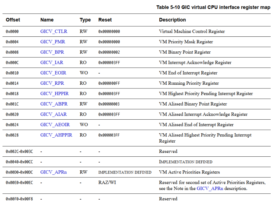
GICH_LRn register implementation: interrupt injection

Writing to the GICH_LRn register can inject interrupts into the VM.
Experiment 10: Injecting Interrupts into a VM
Experiment objective: Become familiar with how GIC v2 injects interrupts.
Experiment requirements: Implement interrupt injection in BenOS, and inject the virtual timer interrupt into the VM. Steps are as follows:
- Enable GIC virtualization, GICH_HCR.EN = 1
- Map the GICC in the VM_interface access address to the physical GICV_interface
- Emulate the Distributor in the hypervisor.
- When the virtual timer in the VM triggers an interrupt, it is routed to the hypervisor at EL2 for handling.
- The hypervisor writes the interrupt information into the GICH_LRn register to inject the interrupt into the VM.
- EOI mode: handled by the hypervisor or injected into the VM for handling.
- The GIC driver of the GuestOS in the VM reads the interrupt number and handles the interrupt.
Points to note when emulating vDistributor
- The Distributor seen by the VM is emulated by the hypervisor.
- When emulating vDistributor, the hypervisor needs to consider the issue of concurrent access between the VM and the hypervisor.
- Some registers of the Distributor are described by interrupt number. For example, a few bits are used to describe the attributes of one interrupt number, so the same register can describe n interrupt sources.

If vDistributor recklessly writes such registers directly through trap and emulate, it will corrupt the hypervisor’s original state.
Method to avoid conflicts:

Given reg_base,far_addr,field_width, we can calculate far_The starting start_hwirq number corresponding to addr.
12345 | // Pseudo-code: iterate over the 4 interrupt numbers covered by this register field.for (irq = start_hwirq; irq < start_hwirq + 4; irq++) if (irq owned by hypervisor) continue; update_reg_field(); |
Virtualization Host Extensions
TODO