Timeline
Timeline
2025-10-31
init
This article introduces the ARM ACE (AXI Coherency Extensions) hardware cache coherence solution, which is based on the AXI bus and achieves cache coherence among multiple masters by adding signal lines, transfer channels, and transactions. The article discusses the basic ideas of ACE, including the snoop mechanism, 5-state cache state transitions (valid, invalid, unique, shared, clean, dirty), and newly added signals such as AxDOMAIN, AxSNOOP, and AxBAR. It also explains the roles of shareability domains (Non-shareable, Inner Shareable, Outer Shareable, System), and illustrates the processing flow of snoop transactions through multiple examples. The article focuses on analyzing the key role of RACK/WACK signal lines in ensuring transaction ordering and solving cache coherence issues, while also introducing the implementation mechanism of exclusive access and DVM (Distributed Virtual M
Reference documents:

ACE
- ACE (AXI Coherency Extensions) is a hardware cache coherence solution based on the AXI bus.
- Focuses on system-level cache coherence.

The ACE interface was first supported starting with the Cortex-A15/A7 big.LITTLE architecture.

Cortex-A9 does not support the ACE interface; it connects to L2 and Memory via the AXI interface.

Cortex-A15 supports the ACE interface. In the big.LITTLE architecture, the big cluster and little cluster connect to the CCI bus via ACE.

- Three masters, each with a local cache. ACE allows all three masters to have the same cache copy of the same memory address.
- Here, master generally refers to a CPU cluster or a controller with a cache.
- ACE ensures that for a given address, all masters can access the correct data.

ACE focuses on system cache coherence issues among masters with caches, such as the Cortex-A72 family and Cortex-A53 family.
ACE-Lite is used to connect hardware I/O devices without caches, but these devices need to access memory that is system cache coherent, such as GPUs, SMMUs, etc. The DVM interface is used to broadcast TLB invalidation.
Basic idea of ACE implementation.
- NeedImplement a snoop mechanism to ensure cache coherence among multiple masters.
- Add new signal lines and new transfer transactions on top of AXI to implement snooping.
- Add new transfer channels on top of AXI.
- Implement a 5-state cache state transition mechanism.(Because some masters use MESI, some use MOESI, etc.)
- ACE supports memory barrier (removed in ACE5).
- ACE supports exclusive access.
- ACE supports DVM.
ACE state machine.
valid: cache line is valid
invalid: cache line is invalid
unique: indicates this cache line is exclusive, only the current master has it
shared: multiple masters have copies of this cache line
clean: indicates the cache line content is consistent with memory
dirty: cache line content is inconsistent with memory, needs to be written back to memory later

Similar to MOESI protocol

New channels added by ACE

New signals added by ACE

- AxDOMAIN: used to indicate shareability domain:
- Non-shareable,Inner Shareable,Outer Shareable,System
- AxSNOOP: used to indicate the type of snoop transaction
- AxBAR: indicates initiating a barrier transaction (removed in ACE5)
- AWUNIQUE: used to optimize cache state transitions for write transactions
AxDOMAIN signal line


AxSNOOP signal line

- AxSNOOP: used to indicate the type of snoop transaction
- Non-snooping
- Coherent
- Memory update
- Cache maintenance
- DVM
- barrier


shareability domains
Before initiating coherency or barrier transactions, the master uses this to determine which masters these transactions should be sent to
- Coherent transactions: determine which masters may have copies of this data, used to send snoop transactions
- Barrier transactions: determine which masters will establish ordering relationships, and how far the barrier transaction needs to propagate
Supports 4 shareability domains:
- Non-shareable: contains only one master
- Inner Shareable
- Outer Shareable
- System

4 shareability domains

- Inner share: usually refers to the caches integrated inside the CPU, which are closest to the processor core. For example, the Cortex-A72 core can integrate L1 and L2 caches internally.
- Outer share: caches extended through the system bus, such as an extended L3 cache connected to the system bus.


Snoop transaction

Example 1: shareable read and miss


Finally:

Example 2: shareable read and hit


Example 3: shareable write 1 (full cache line)


Example 4: Shareable write 2 (partial cache line)
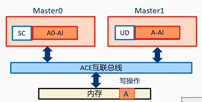
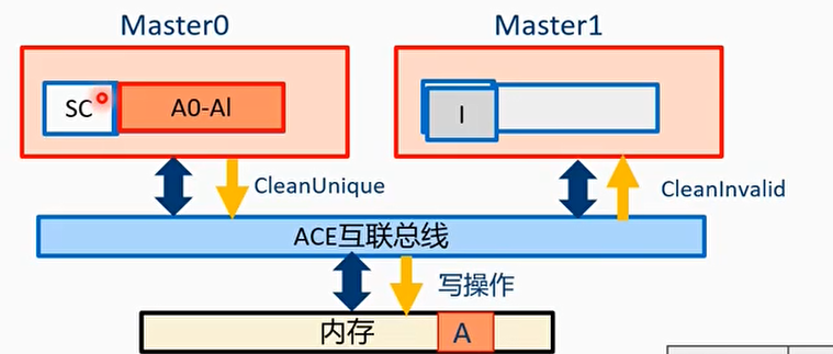


Example 5: Simultaneously initiating ReadUnique write operations
- At time T0, the cache line states of Master0 and Master1 are both I, and the initial value at address A is 0x11223344
- At time T, Master0 and Master1 simultaneously initiate write operations to address A
- Master0 wants to write 0x55667788 to address A
- Master1 wants to write 0xaabbccdd to address A

The bus will arbitrate, processing one request before handling the other


RACK and WACK signal lines
- In Example 5, the RACK signal line is used to indicate that the ReadUnique transaction has completed
- On the AXI bus, multiple outstanding and out-of-order transactions are supported, but in ACE, cache coherence issues are very likely to occur
- The RACK signal line is used to indicate that a read transaction has completed
- The WACK signal line is used to indicate that a write transaction has completed
- The interconnect bus IP uses the RACK/WACK signal lines to ensure,that the previous transaction to an address has been processed before sending snooping of other transactions to other masters
- For a read transaction, when the RLAST signal is asserted, it indicates that the last read transfer is complete, and then the master can send the RACK signal
- For a write transaction, after the write response channel returns a response handshake, the master can send the WACK signal
Example 6: Use of the RACK signal line - Problem Introduction
At time T0: The cache line states of Master0 and Master1 are both SC
At time T1: Master0 wants to rewrite the data at address A to: 0xAABBCCDD
At time T2: Master1 performs a read operation on address A


Root Cause
When Master1 initiates a ReadShared transaction, Master1 assumes that Master0’s previous MakeUnique transaction has completed, but in reality it is blocked in some intermediate state and has not yet completed.
Example 6: Use of the RACK signal line - Problem Solution
Solution: Master0 uses the RACK signal to tell the bus IP that the MakeUnique transaction has completed, and only then can the bus initiate other snoop-related transactions.


exclusive access
Exclusive access flow
- Execute exclusive load
- Calculate
- Execute exclusive store
- If another master writes to this address, fail
- If no other master writes to this address, success
For Non-shareable and System Shareable memory addresses, exclusive access behaves the same as AXI.
For Inner Shareable and Outer Shareable memory
- The master exclusive monitor ensures that after the exclusive load, no other master writes to this address.
- The PoS exclusive monitor of the bus interconnect implements access serialization.

DVM(Distributed Virtual Memory)
- Send broadcast to other masters:
- TLB invalidate
- Branch Predictor Invalidate
- Physical Instruction Cache Invalidate
- Virtual Instruction Cache Invalidate
- Synchronization

DVM transfer transactions - DVM message transactions

DVM message transaction processing flow:
- The master sends a DVM message request through the read address channel.
- After the bus receives it, it sends a snoop to other masters.
- After the other masters receive it, they respond via the snoop response channel.
- After the bus collects all responses, it sends a response packet to the initiating master via the read data channel.
DVM transfer transactions - DVM Synchronization and DVM Complete transactions

DVM sync and complete transaction processing flow:
- The initiating master sends a DVM synchronization request via the read address channel.
- After the bus receives it, it sends a snoop broadcast to other masters.
- After the other masters receive it, they send a response via the snoop response channel.
- After the bus collects all response packets, it sends a response packet to the initiating master via the read data channel.
- Each participating master, after completing TLB invalidation, sends a DVM complete transaction via the read address channel.
- After the bus receives the DVM complete, it immediately responds to the master.
- After the bus collects the DVM complete transactions from all participating masters, it sends a DVM complete to the initiating master via the snoop address channel.
- The initiating master responds to the bus via the snoop response channel.
DVM message packetization

Different encodings of AxADDR implement different instructions, such as TLBI.
Example: Modifying PTE

ACE-Lite
- ACE-Lite is applied to hardware devices that do not need to participate in system cache coherence, such as hardware devices without a local cache.
- GPU
- SMMU

- Transactions supported by ACE-Lite
- Non-coherent transactions: ReadNoSnoop, WriteNoSnoop
- Partially coherent transactions: ReadOnce, WriteUnique, WriteLineUnique
- Cache maintenance transactions: CleanShared, CleanInvalid, MakeInvalid

ACE-Lite + DVM combination

ACE-Lite+DVM application scenarios

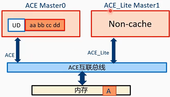
Example: ACE_Lite master performs partial write
- At time T0: the cache line state on Master0 is UD, assuming the cache line value is: aa bb cc dd
- At time T1: master1 performs a partial cache line write operation to address A, writing 11 22 into it