
Timeline
Timeline
2025-10-30
init
This article introduces ARM SMMUv3 (System Memory Management Unit architecture version 3) technology, explains the role of SMMU as an IOMMU in translating device virtual addresses to physical addresses, and its necessity in solving DMA access security and performance issues in bare-metal and virtualization scenarios. The article details the development history of SMMU, the implementation of the MMU-600 controller, and its supported features such as two-stage address translation and Bypass mode. At the architecture level, it analyzes the composition of TBU and TCU and the DTI connection method, and deeply explains the structure and indexing process of StreamID, SubstreamID, Stream Table, and Context Descriptor tables, including configuration examples of second-level tables. In addition, the article also introduces the working mechanism of Command and Event queues, as well as the IOMMU framework, controller driver, dma-mapping, IOMMU Domain, and iom
Reference documents:

Technical manual:
- System Memory Management Unit Architecture Specification, SMMU architecture version 3
- MMU-600 System Memory Management Unit, Technical Reference Manual
What is SMMU/IOMMU
- SMMU is an IOMMU (Input/Output Memory Management Unit) implemented by ARM, which translates the virtual addresses accessed by devices into physical addresses.
- AMD has also implemented IOMMU.
- Intel’s VT-d technology

Bare-metal OS scenario

DMA access by IO devices may have problems:
- IO devices get physical addresses, and they can access all memory addresses. Therefore, DMA can corrupt other devices or system memory, for example, malicious IO devices.
- There is also no protection for device drivers, for example, malicious drivers.
- Information is easily leaked between IO devices: side-channel attack.
Virtualized scenario

Disadvantages:
Each DMA operation needs to trap into the VMM to allocate physical memory for the IO device, resulting in a performance loss (about 20-30%).
Solution: SMMU

Each IO device has its own page table.
Scatter-gather means that an IO device can use a contiguous range of virtual addresses, but the final translated physical addresses do not necessarily need to be contiguous.
SMMU development history

Usage of SMMU

The CPU can access devices using the MMU; device access to memory needs to go through the SMMU.
MMU-600 controller
- SMMUv3 is a spec, and MMU-600 is a controller implemented based on the SMMUv3.1 specification.
- MMU-600 translates device IOVA to PA, supporting two-stage address translation or Bypass mode.
- Stage1: Translate IOVA->PA or IOVA->IPA.
- Stage2:IPA->PA
- Both: IOVA->IPA->PA
- Bypass mode (skip SMMU)
- Features
- Compatible with SMMUv3.1
- Supports ARMv8 AArch32 and AArch64 page table formats
- Supports 4KB, 16KB, and 64KB pages
- Supports PCIe, ATS, and PASIDs
- Supports PRI (Page Request Interface)
- Supports ACE5-Lite atomic operations
- Supports translation faults, software can implement demand paging
- Supports GICv3 integration and message-based interrupts
MMU-600 block diagram

MMU-600 internal composition
- TBU (Translation Buffer Unit)
- Contains TLB to cache translation results
- Each connected master has at least one TBU
- If the TBU does not find a TLB entry, it sends a request to the TCU
- TCU(Translation Control Unit)
- Hardware unit that performs address translation
- MMU-600 has only one TCU
- Manages memory requests
- Traverses page tables
- Performs page table configuration
- Implements backup caching structures
- SMMU programming interface
- DTI
- Used to connect TBU to TCU
- Uses AXI Stream protocol

StreamID
- A DMA transfer includes: destination address, size, read/write attributes, security attributes, shareability attributes, cache attributes, and StreamID.
- StreamID is used to associate a device (function).
- StreamID is used to index the Stream Table, which contains per-SMMU page table information.
- For PCIe devices, StreamID[15:0] == RequesterID[15:0], which equals BDF.
- Bits[15:8] Bus number
- Bits[7:3] Device number
- Bits[2:0] Function number
- For non-PCIe devices, the StreamID is obtained through DTS (so the StreamID is fixedly allocated by the platform).

Traverse the Stream Table.
- Each STE (Stream Table Entry) in the Stream Table contains:
- Stage2 translation page table base address.
- Points to a Context Descriptor table, which contains the Stage1 translation page table base address.
- Use StreamID to index the Stream Table.
- The Stream Table needs to be created and populated by OS software.
- When the StreamID width is greater than 6 bits (i.e., the number of STEs is greater than 64), a two-level table must be used.
- StreamID[n:x] indexes the first-level table, and StreamID[x-1:0] indexes the second-level table.
- n represents the most significant bit of StreamID, typically 15.
- x is the split point, set by STRTAB_BASE_CFG.SPLIT configuration.
- For example: n=15, x=8, then StreamID[15:8] indexes the first-level table, and StreamID[7:0] indexes the second-level table.

Two-level table example.
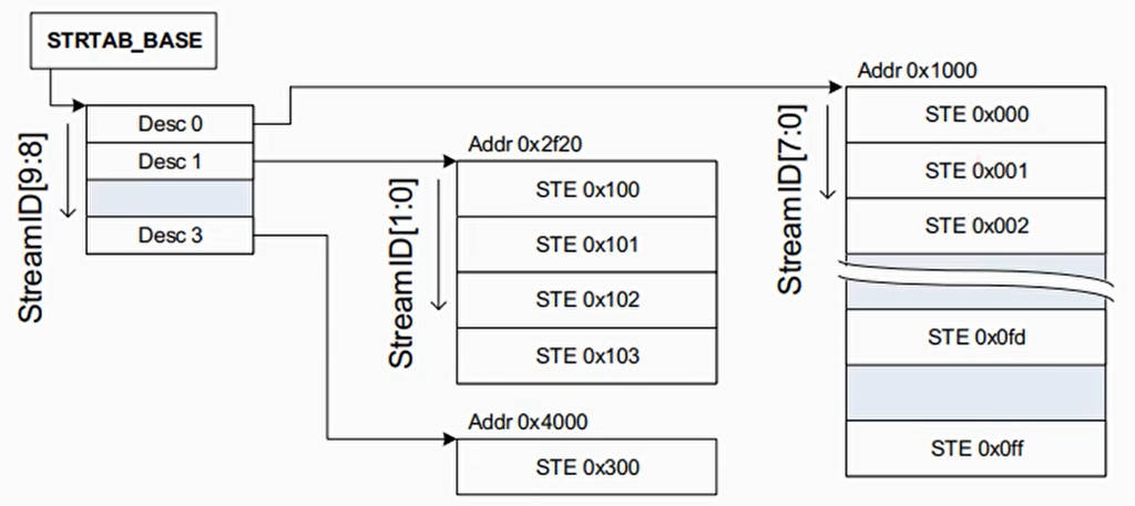
Assume StreamID is only 10 bits, i.e., StreamID[9:0], and assume X is 8, then use StreamID[9:8] to index the first-level table, and use StreamID[7:0] to index the second-level table.
The first-level table has 4 entries, and each second-level table has 256 entries.
StreamID is 10 bits in total. 2^10 = 1024, meaning it can index up to 0~1023 STEs.
Context Descriptors table.
CD contains the stage 1 page table base address, ASID, page table attributes, etc.
S1ContextPtr in STE points to CD
The stage 2 page table base address is in the STE
Software management:
- Virtualization: Hypervisor manages Stream Table and stage 2 page tables, Guest OS manages CD and stage 1 page tables
- Bare-metal OS manages Stream Table and CD

Context Descriptors table. SubstreamID

SubstreamID S1ContextPtr in STE points to a CD (Context Descriptor) table, and SubstreamID is used to index this table
Each CD contains the page table base address used in stage 1
A device may be used by multiple processes. The SMMU distinguishes them via SubstreamID; each process can have one SubstreamID.
For PCIe devices, PASID is used as the SubstreamID
Summary

Command and Event queues
- The command queue is used for input, and the event queue is used for output. Each queue has a producer and a consumer.
- The output queue (event queue) contains data produced by the SMMU and is consumed by software. The input queue (command queue) has data produced by software and is consumed by the SMMU.


For detailed descriptions of each command, see Chapter 4 of the SMMUv3 manual.
Linux IOMMU driver framework
The IOMMU driver has two main functions:
- Provide DMA interfaces and functions for IO devices
- Provide SVA (Shared Virtual Addressing) functionality for IO devices, sharing the virtual address space of an IO device with a process
IOMMU includes:
- IOMMU framework
- IOMMU controller driver
- IOMMU dma-mapping
- Interfaces provided by IOMMU to IO devices

- IOMMU Domain is mainly used to provide the ability to access the IOMMU controller
- iommu_group is the smallest resource isolation unit
- Generally, one device occupies one iommu_group. Multiple devices that are based on some hardware topology relationship and are security-trusted, or point-to-point protected transport devices, can be added to one iommu group.
- A server system may have multiple IOMMU controllers.


The bridge between IOMMU domain and SMMU controller - iommu_ops

SMMU driver: DMA

Writing an IOMMU IO device driver
Manual setup
- Allocate an IOMMU domain
1 | domain = iommu_domain_alloc() |
- Add device dev to the IOMMU domain
1 | iommu_attach_device(domain, dev) |
- Establish mapping
1 | iommu_map() |

Automatic setup
- For PCI devices or platform devices, automatically detect and initialize IOMMU through bus scanning.
driver_probe_device()->
dev->bus->dma_configure(dev)->
platform_dma_configure()/pci_dma_configure()->
of_dma_configure()
- Automatically set up struct dma_map_ops *dma_ops for IOMMU
For PCI and platform devices, DMA API interfaces can be used, e.g., dma_map_page()
of_dma_configure()->
arch_setup_dma_ops()->
dev->dma_ops = &iommu_dma_ops;
- arch/arm64/mm/dma-mapping.c

IO device SMMU initialization flow

Summary

SVA(Shared Virtual Addressing)
Sharing process address space between processes and devices
(Based on Linux 5.15 kernel)
Why SVA?
Traditional DMA mode

SVA mode

In DMA mode, it is difficult to share complex data structures between CPU and GPU/FPGA/accelerator cards.

Linux SVA framework

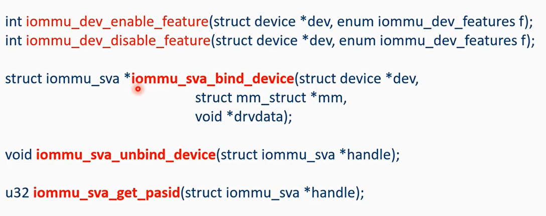
From the driver perspective, what new API interfaces are added?
Summary

I/O page fault
- CPU-side page fault: goes through the CPU page fault handler._mm_fault
- Device-side page fault:
- PCIe devices: PRI extension (Page Request Interface)
- Platform devices: use the SMMU stall mode
- Stall mode: When an I/O device triggers a fault, the transaction is paused, and the event is recorded in the event queue. The OS software needs to handle it, then sends a CMD_RESUME command to resume the transaction.

Question: Why does the I/O device-side page fault handling call the CPU-side handler?_mm_fault() to establish the VA->PA page table entries. What about the I/O device’s page table? Who establishes it?
SVA: share one set of page tables.
TLB invalidation operation

- When the CPU side modifies the mm or releases memory
- Call flush_tlb() to invalidate the CPU-side TLB.
- Invalidate the corresponding IOTLB on the I/O device side and the PCIe ATC’s IOTLB through the callback function registered by mmu_notifier.

- Is it possible for the I/O device to actively modify the VA->PA mapping?
- In non-SVA cases, via iommu_map and iommu_unmap interface to implement allocation and release of DMA buffer. iommu_unmap()->iotlb_sync()
- In the SVA case, the virtual address allocated on the CPU side can be used as IOVA. When an I/O device triggers a page fault, it directly goes through the I/O page fault handling flow.
PCIe’s new ATS (Address Translation Services)

- ATS mechanism in PCIe: The device caches VA-to-PA mappings, so when the device uses PA for memory access, it does not need to go through IOMMU page table translation.
- The ATC (Address Translation Cache) of a PCIe device has its own TLB.
- Before performing DMA, the device checks whether the ATC has an entry corresponding to the VA.
- If yes: directly use the PA to access memory.
- If no: send an ATS request to the SMMU; after the SMMU finds the PA, it replies with an ATS completion.
- The PCIe ATS specification defines the format of ATS request and completion message packets.
- Address Translation Services Revision 1.1
- SMMU driver:
- Enable ATS
- ATS invalidation operation. When the SMMU changes VA->PA, the SMMU needs to send an ATS invalidation request to the PCIe ATC.
- SMMU provides CMD_ATC_INV command

PRI (Page Request Interface) support
- The benefit of the PRI mechanism is that when preparing to initiate a DMA operation, there is no need to prepare (pin) the DMA buffer in advance.
- Use case: high-speed NICs; in burst scenarios, the Host does not need to reserve and occupy a large amount of buffer in advance.
- PRI mechanism:
- When an ATC lookup results in a TLB miss, a Page Request Message is sent.
- The Root Complex (RC) sends the message to the SMMU.
- The SMMU writes the page request to the PRI queue and triggers a PRI interrupt.
- OS software allocates physical memory.
- OS software replies with CMD_PRI_RESP command
