
Timeline
Timeline
2025-10-26
init
This article introduces the concept, causes, and solutions of cache coherency in the ARM architecture. The article first explains the inconsistency problem caused by multiple copies of the same data in multi-level caches, and introduces bus snooping protocols (such as MESI) and the evolution of ARM cache coherency, from single-core to multi-core and then to the big.LITTLE architecture, involving the CCI-400/500 interconnect IP and the ACE/CHI protocols. It then compares the advantages and disadvantages of three solutions: disabling caches, software maintenance, and hardware maintenance, with emphasis on the states and operations of the MESI protocol, and analyzes state changes through examples. In addition, it discusses the cache false sharing problem and its solutions (cache line padding/alignment), and finally mentions that ARMv8 adopts the MOESI protocol.
Reference documents:

Why is cache coherency needed?
- Different levels of cache in the system have different data copies, for example, each CPU core hasL1 cache

- Cache coherency focuses on the consistency of the same data across multiple caches and memoryThe main method to solve cache coherency isbus snooping protocol, for exampleMESIProtocol
- Examples where cache coherency needs attention:
- Using DMA in drivers(data cache and memory are inconsistent)
- Self-modifying code(data in the data cache may be newer than that in the instruction cache)
- Modified the page table(data stored in the TLB may be stale)
ARMofcacheEvolution of coherency

Cortex-A8 is a single-core architecture, so there is no cache coherency issue between cores, but there is a coherency issue between DMA and cache
The multi-core version of Cortex-A9 (MPCore) has cache coherency issues between cores; the usual approach is to implement a hardwareMESIProtocol
Cortex-A15 introduced the big.LITTLE architecture (big.LITTLE), for example, one cluster is all big cores and another is all little cores, thereforecache coherency is also needed between clusters, which requiresAMBA Coherency Extensionto handle, and in ARM there are ready-madeIP(in IC design , an IP core = a designed and verified circuit module that can be directly reused as a ‘building block’) can be used, for exampleCCI-400andCCI-500
Single-core processor (Cortex-A8)
- Single core, no cache coherence issue
- Cache management instructions only affect a single core
Multi-core processors (Cortex-A9 MP and later processors)
- Hardware supports cache coherence
- Cache management instructions are broadcast to other CPU cores

System-level cache coherence
- System cache coherence requires a cache-coherent internal bus (cache coherent interconnect)
- AMBA 4Protocols includeACE(AXI Coherency Extensions)
- AMBA 5Protocols includeCHI

Solutions for cache coherence
Disable cache
- Advantages: simple
- Disadvantages: low performance, increased power consumption
Software-maintained cache coherence
- Advantages: simple hardware RTL implementation
- Disadvantages:
- Increased software complexity. Software must manually clean/flush cache or invalidate cache
- Increased debugging difficulty
- Reduced performance and increased power consumption
Hardware-maintained cache coherence
MESIMaintained by protocolMulti-core cache coherence。ACE interfaceto implement system-level cache coherence
- Advantages: transparent to software
- Disadvantages: increases the difficulty and complexity of hardware RTL implementation
Cache coherence among multiple cores
Reasons for cache coherence issues in multi-core CPUs:The same memory data has multiple different copies in the L1 caches of multiple CPU cores, leading to data inconsistency
The key to maintaining cache coherence istracking the state of each cache line, and updating the state of cache lines in the caches of different CPU cores based on processor read/write operations and corresponding bus transactions, thereby maintaining cache coherence
Cache coherence protocols
Snooping protocol (snooping protocol), each cache must be snooped or snoop on the bus activity of other caches
Directory protocol (directory protocol), globally and uniformly manage cache states
MESIProtocol:
- In 1983,James GoodmanproposedWrite-Oncethe bus snooping protocol, which later evolved into the most popularMESIProtocol
- All bus transactions are visible to all other units in the system, because the bus is abroadcast-based communicationmedium, and therefore can be snooped by each processor’s cache

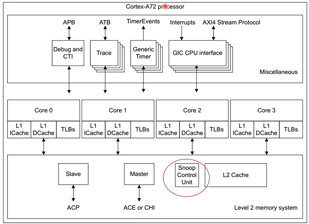
Snoop control unitUnit implementationBus snooping and broadcasting
Each CPU’s L1 cache also implements bus snooping functionality.
MESI protocol
- Each cache line has four states.
- Modified (Modified)
- Exclusive (Exclusive)
- Shared (Shared)
- Invalid (Invalid)

- ModifyMand exclusive stateEFor cache lines in the Modified and Exclusive states, the data is exclusive. The difference is that data in the Modified state is dirty and inconsistent with memory, while data in the Exclusive state is clean and consistent with memory. Dirty cache lines are written back to memory, and then the state changes to Exclusive.
- Shared stateSFor cache lines in the Shared state, data is shared with other caches; only clean data can be shared by multiple caches.
- IThe state indicates that this cache line is invalid.
MESI operations

MESI state diagram

MESI mainly addressesThe consistency between local caches in each CPUproblem


An example of MESI protocol analysis
- Assume there are 4 CPUs in the system, each with its own L1 cache, and they all want to access data A at the same address, with a size of 64 bytes.
- At time T0: none of the 4 CPUs’ L1 caches have cached data A, and the cache line state is I (Invalid).
- At time T1: CPU0 is the first to initiate an access to data A.
- At time T2: CPU1 also initiates a read operation.
- At time T3: CPU2’s program wants to modify the data in data A.
- Please analyze the changes in MESI states during the above process.
Time T0 None of the 4 CPUs’ L1 caches have cached data A, and the cache line state is I.

Time T1 CPU0 is the first to initiate an access to data A.

Time T2 CPU1 also initiates a read operation.

Time T3 CPU2’s program wants to modify the data in data A.

Cache False Sharing
- If multiple processors simultaneously access different data within the same cache line, it can cause performance problems.
- For example: suppose thread 0 on CPU0 wants to access and update the x member of the struct data data structure, and similarly thread 1 on CPU1 wants to access and update the y member of the struct data data structure, where both x and y members are cached in the same cache line.

Analysis:


Afterwards, it will repeatedly alternate between T4 and T5, contending for the cache line, constantly invalidating the other’s cache line, and triggering cache write-back to memory.
Solution
- The solution to cache false sharing isto place data operated on by multiple threads in different cache lines, usually by usingcache line padding technologyorcache line alignment technology, that is, align data structures to cache lines and fill them as much as possible to the size of a cache line.
- The following code defines a counter_s data structure, whose starting address is aligned to the size of a cache line, and the members of the data structure are padded with pad[4]. Thus, counter_s is exactly the size of a cache line, 64 bytes, and its starting address is also cache line aligned.

Make counter_s exclusively occupy one cache line as much as possible, without sharing a cache line with other data structures.
MOESI protocol
The ARMv8 processors use the MOESI protocol
Modified
The most up-to-date version of the cache line is within this cache.
No other copies of the memory location exist within other caches.
The contents of the cache line are no longer coherent with main memory.
Owned
This describes a line that is dirty and in possibly more than one cache.
A cache line in the owned state holds the most recent, correct copy of the data.
Only one core can hold the data in the owned state. The other cores can hold the data in the shared state.
Exclusive
- The cache line is present in this cache and coherent with main memory.
- No other copies of the memory location exist within other caches.
Shared
The cache line is present in this cache and is not necessarily coherent with memory, given that the definition of Owned allows for a dirty line to be duplicated into shared lines.
It will, however, have the most recent version of the data.
Copies of it can also exist in other caches in the coherency scheme.
Invalid
- The cache line is invalid.
The following rules apply for the standard implementation of the protocol:
- A write can only be performed if the cache line is in a Modified or Exclusive state. If it is
in a Shared state, all other cached copies must be invalidated first. A write moves the line
into a Modified state. - A cache can discard a shared line at any time, changing it to an Invalid state.
- A Modified line is written back first.
- If a cache holds a line in a Modified state, reads from other caches in the system receive
the updated data from the cache. Conventionally, this is achieved by first writing the data
to main memory and then changing the cache line to a Shared state, before performing a
read. - A cache that has a line in an Exclusive state must move the line to a Shared state when
another cache reads that line. - A Shared state might not be precise. If one cache discards a Shared line, another cache
might not be aware that it can now move the line to an Exclusive state.
Snoop Control Unit(SCU)
The processor cluster contains a Snoop Control Unit (SCU) that contains duplicate copies of the tags stored in the individual L1 Data Caches. The cache coherency logic therefore:
- Maintains coherency between L1 data caches.
- Arbitrates accesses to L2 interfaces, for both instructions and data.
- Has duplicated Tag RAMs to keep track of what data is allocated in each core’s data.

Each core in the figure has its own data and instruction caches. The cache coherence logic contains local copies of the tags from the D cache. However,**the instruction cache does not participate in coherence.**There is 2-way communication between the data cache and the coherence logic. ARM multicore processors also implement optimizations that can directly copy clean data and move dirty data between participating L1 caches without accessing and waiting for external memory. This activity is handled by the SCU in a multicore system.
The Snoop Control Unit (SCU) maintains coherence among the L1 data caches of each core and is responsible for managing the following interconnect operations:
- Arbitration.
- Communication.
- Cache-2-cache and system memory transfers.
The processor also provides these functions to other system accelerators and non-cached DMA-driven peripherals to improve performance and reduce system-wide power consumption.
This system coherence also reduces the software complexity involved in maintaining software coherence within each operating system driver. Each core can be individually configured to participate or not participate in the data cache coherence management scheme. The SCU device inside the processor automatically maintains L1 data cache coherence among the cores within the cluster.
Since executable code changes much less frequently,**this feature is not extended to the L1 instruction cache.**Coherence management is implemented using a MOESI-based protocol, optimized to reduce the number of external memory accesses. For coherence management to be effective for memory accesses, all of the following conditions must be true:
- The SCU is enabled through control registers located in a private memory region. The SCU has configurable access control that restricts which processors can
configure it. - The MMU is enabled.
- The accessed page is marked as Normal Shareable, with a cache policy of write-back, write-allocate. However, device and strongly-ordered memory are not cacheable, and from the core’s perspective, write-through cache behaves like uncached memory.
The SCU can only maintain consistency within a single cluster. If there are additional processors or other bus masters in the system, explicit software synchronization is required when they share memory with the MP block.
Inter-system cache coherence


ARM’s CCI for the server market is CoreLink CCN.


Example of reading data


Example of writing data


Cache coherence cases
Case 1: Avoiding false sharing in cache
- Some commonly used data structures are defined with conventionsData structures are aligned to the L1 cache line. For example, use the following macro to align the base address of a data structure to the L1 cache line.
1 | |
Frequently accessed members of a data structure can occupy a separate cache line., or related members arestaggered from each other in the cache line, to improve access efficiency. For example, the struct zone data structure usesZONE_PADDINGtechnique (padding bytesmethod) to place frequently accessed members in different cache lines.

Frequently accessed members of a data structure can occupy a separate cache line.
Case 2: Cache coherence for DMA
DMA (Direct Memory Access) is direct memory access. During the transfer process, it does not require CPU intervention and can read and write data directly from/to memory.
- Reasons why DMA causes cache coherence problems:
- DMA directly operates the system bus to read/write memory, and the CPU is not aware of it.
- if**The memory address modified by DMA is cached in the CPU’s cache.**Then the CPU does not know that the memory data has been modified, and the CPU still accesses the old data in the cache, leading to cache coherence problems.

Solutions to DMA cache coherence
Hardware solution: requiresACE bus support(consult SoC vendor)
Use non-cacheable memory for DMA transfers
- Disadvantage: When DMA is not in use, CPU access to this buffer causes performance degradation.
Software intervenes in cache coherence; software maintains cache coherence based on the direction of DMA data transfer.
Case 1: Memory -> Device FIFO (device such as a network card,Read memory data to the device FIFO via DMA)
- Before the DMA transfer, the CPU’s cache may have cached the memory data. A cache clean/flush operation needs to be called to write the cache contents back to memory, because the CPU cache may contain the latest data.

The CPU's cache has the latest data, but the DMA reads old data from memory. Case 2: Device FIFO -> Memory (the device writes data to memory)
- Before the DMA transfer, the cache needs to be invalidated. Because at this time the latest data is in the device FIFO, the data cached by the CPU is stale; the cache must be invalidated before writing new data.

The CPU's cache may still contain useless data.
Case 3: Self-modifying code
The instruction cache and data cache are separate. The instruction cache is generally read-only.
Cache coherence issues between instruction cache and data cache. Instructions usually cannot be modified, but in some special cases instructions may be modified.
Self-modifying code modifies its own instructions during execution (to prevent software cracking, or to dynamically modify the program during gdb debugging). The process is as follows:
- Write the new instruction to memory and load it into the data cache.
- The program (CPU) modifies the new instruction, and the data cache holds the latest instruction.
Problem:
- The instruction cache still caches the old instruction, while the new instruction is still in the data cache.

Self modifying code
Solution approach:
- Use a cache clean operation to write the cache line data back to memory.
- Use a DSB instruction to ensure other observers see that the clean operation has completed.
- Perform an invalidate operation on the instruction cache.
- Use a DSB instruction to ensure other observers see that the invalidate operation has completed.
- Use an ISB instruction to make the program refetch instructions.

Cache Experiment 2: False Sharing

1234567891011121314151617181920212223242526272829303132333435363738394041424344454647484950515253545556575859606162 | struct data_with_false_sharing { unsigned long x; unsigned long y;} __attribute__((__align__(64)));struct padding { char x[0]} __attribute__((__align__(64)));struct data_without_false_sharing { unsigned long x; struct padding _pad; unsigned long y;} __attribute__((__align__(64)));void *access_data(void *param) { unsigned long *data = (unsigned long *)param; unsigned long i; for (i = 0; i < MAX_LOOP; i++) { *data = i; }}int main(void) { struct data_with_false_sharing data_wfs = {1, 2}; struct data_without_false_sharing data_wofs = {.x = 1, .y = 2}; pthread_t thread_1; pthread_t thread_2; unsigned long total_time; struct timespec time_start, time_end; clock_gettime(CLOCK_REALTIME, &time_start); pthread_create(&thread_1, NULL, &access_data, (void *)&data_wfs.x); pthread_create(&thread_2, NULL, &access_data, (void *)&data_wfs.y); pthread_join(thread_1, NULL); pthread_join(thread_2, NULL); clock_gettime(CLOCK_REALTIME, &time_end); total_time = (time_end.tv_sec - time_start.tv_sec) * 1000 + (time_end.tv_nsec - time_start.tv_nsec) / 1000000; printf("cache with false sharing: %lu ms \n", total_time); clock_gettime(CLOCK_REALTIME, &time_start); pthread_create(&thread_1, NULL, &access_data, (void *)&data_wofs.x); pthread_create(&thread_2, NULL, &access_data, (void *)&data_wofs.y); pthread_join(thread_1, NULL); pthread_join(thread_2, NULL); clock_gettime(CLOCK_REALTIME, &time_end); total_time = (time_end.tv_sec - time_start.tv_sec) * 1000 + (time_end.tv_nsec - time_start.tv_nsec) / 1000000; printf("cache without false sharing: %lu ms \n", total_time);} |

Cache Experiment 3: Flush Cache Experiment

Result:

1234567891011121314151617181920212223242526272829303132333435363738 | .global get_cache_line_sizeget_cache_line_size: mrs x0, ctr_el0 ubfm x0, x0, #16, #19 mov x1, #4 lsl x0, x1, x0 ret/* flush_cache_range(start, end) */.global flush_cache_rangeflush_cache_range: stp x29, x30, [sp, -16]! // start mov x8, x0 // end mov x9, x1 bl get_cache_line_size // x3 = cache_line_size -1 sub x3, x0, #1 // bit clear, x4 = x8 & (~x3) // Align the start address down to the cache line boundary. bic x4, x8, x3 // Clean cache lines in a loop.1: dc civac, x4 add x4, x4, x0 cmp x4, x9 b.lo 1b dsb ish ldp x29, x30, [sp], 16 ret |
Cache-related sections of the ARMv8 chip manual.
ARM Architecture Reference Manual Armv8, for Armv8-A architecture profile
B2.4 Caches and memory hierarchy
D4.4 Cache Support
D5.11 Caches in a VMSAv8-64 implementation
ARM Cortex-A Series Programmer’s Guide for ARMv8-A
- Chapter 11 Cache
ARM Cortex-A72 MPCore Processor Technical Reference Manual
- 6: Level 1 Memory System
- 7:Level 2 Memory System