
Timeline
Timeline
2025-10-22
init
This article introduces the basic principles and implementation of the ARM interrupt controller, focusing on the GIC controller under the ARM64 architecture and the Legacy Interrupt routing mechanism on the Raspberry Pi 4B. The article first explains the nIRQ/nFIQ pins of the ARM core and the role of the relevant mask bits in PSTATE, then describes in detail the classification of interrupt sources on the Raspberry Pi 4B, including ARM Core, ARM_LOCAL, ARMC, and VideoCore, etc., and explains the read flow of the Legacy IRQ status registers. Taking the ARM Core's generic timer as an example, the article gives the complete handling flow of the EL1 non-secure timer interrupt: from initializing the timer, setting cntp_ctl_el0 and cntp_tval_el0 registers, to enabling TIMER_CNT in CNTRL0_PNS_IRQ, and then to turning on the IRQ master switch of PSTATE. After the interrupt occurs, the CPU jumps to el1_irq assembly function, through kernel_entry saves context, reads IRQ_SOURCE0 to determine the interrupt source, and resets Ti
Reference documents:

Interrupt handling in ARM64 exception handling
- ARMThe core has two interrupt-related pins:nIRQandnFIQ
- eachCPUThe core has a pair of such interrupt-related pins

- There are two bits in the PSTATE state related to interrupts
- I is used to mask IRQ interrupts
- F is used to mask FIQ interrupts
ARM64inGICcontroller
- ARM provides a standard GIC controller, for example, the Raspberry Pi 4B supports GIC-400
- The Raspberry Pi 3B supports the traditional interrupt method (legacy interrupt)
Legacy Interrupt

Interrupt handling process

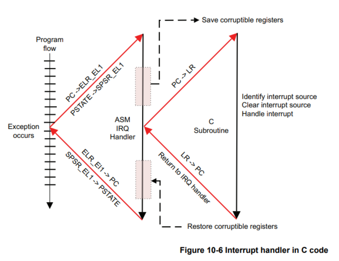
When the processor takes an exception to the AArch64 execution state, all PSTATE interrupt masks are automatically set. This means subsequent exceptions will be disabled. If software wants to support exception nesting, for example, allowing a high-priority interrupt to preempt the handling of a low-priority source, then software needs to explicitly re-enable interrupts.
For the following instruction:
1 | MSR DAIFClr, #imm |

The nested handler requires some additional code. It must save SPSR on the stack._EL1 and ELR_EL1 content. After determining (and clearing) the interrupt source, we must also re-enable the IRQ.
Interrupt sources on the Raspberry Pi 4B

ARM Core n (ARM core interrupt sources)
- PNS timer IRQCorresponding A Non-secure EL1 physical timer
- PS timer IRQCorrespondingA secure EL1 physical timer
- HP timer IRQCorresponds to (Hypervisor)A Non-secure EL2 physical timer
- V timer IRQ Corresponding A virtual timer
- PMU YesPerformance Monitor Unit
- repeated 4 times indicates that each core has a group of such interrupt sources; the Raspberry Pi has 4 cores, so it is repeated 4 times.

Generic Timer ARM_LOCAL (Interrupt sources accessible only by the CPU)
ARMC (Interrupt sources accessible by both CPU and GPU)
VideoCore (GPU core interrupt sources)
The interrupts included are as follows:
VC(VideoCore) peripheral IRQs

VideoCore Peripheral IRQs 
VideoCore Peripheral IRQs ETH_PCIe (PCIe interrupts)
Raspberry Pi 4BofLegacy Interrupt Routing

ARM Core IRQs are directly routed to pre-core routing.
ARMC and VC are routed through the ARMC routing hardware unit.
Legacy IRQ status registers

FIQn/IRQn_PENDING2
FIQn/IRQn_PENDING0
FIQn/IRQn_PENDING1
FIQ/IRQ_SOURCEn
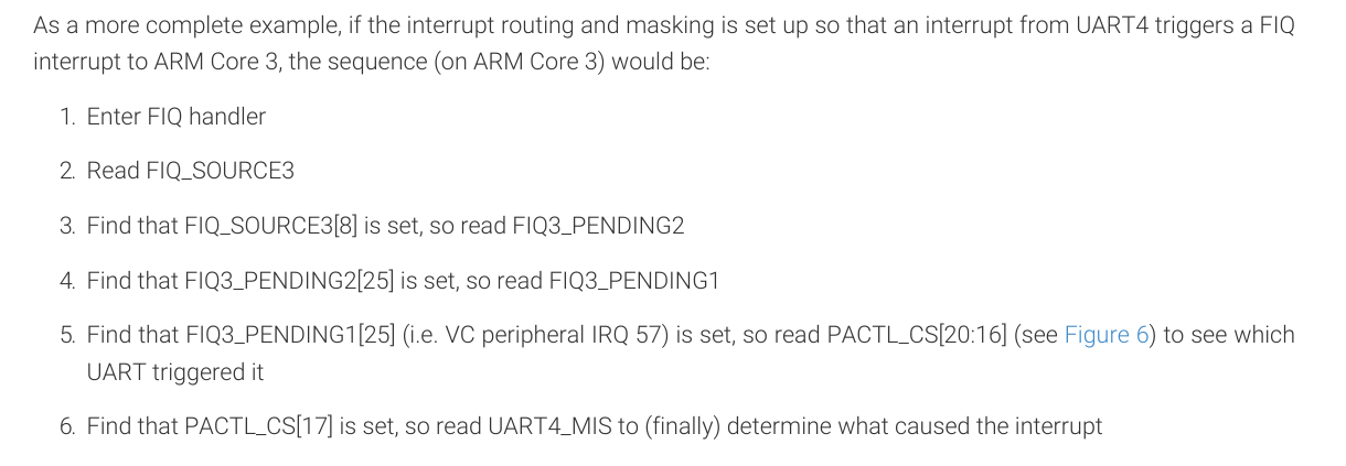
When bit 8 of the source register is set, you need to read the PENDING2 status register.
If bit 24 of PENDING2 is set, you need to read the PENDING0 status register.
If bit 25 of PENDING2 is set, you need to read the PENDING1 register.
Software needs to read the interrupt status registers step by step.
12345678910111213141516171819 | ┌──────────────┐ │ SOURCE寄存器 │ ← ARM_LOCAL_IRQ_SOURCE0 └───────┬──────┘ │ ┌──────────┴──────────┐ │ │ 本地中断? bit8=1?(定时器等) (有外设/GPU中断) │ │ ↓ ↓handle_timer_irq() ┌───────────────┐ │ PENDING2寄存器│ └───────┬───────┘ │ ┌───────────┬───────────┐ │ │ │ bit24=1? bit25=1? 其它位? 去PENDING0 去PENDING1 直接是GPU中断 |
Example
Taking the ARM Core’s generic timer as an example
- Cortex-A72 supports generic timers for 4 ARM cores
- CNT_PS_IRQ Secure EL1 Physical Timer Event Interrupt
- CNT_PNS_IRQ Nonsecure EL1 Physical Timer Event interrupt
- CNT_HP_IRQ Hypervisor Physical Timer Event interrupt, EL2
- CNT_V_IRQ Virtual Timer Event interrupt, EL1

The timer supports two trigger modes


XXX_ELn→ indicates this system register can be accessed at ELn and higher privilege levels。
- for example
CNTP_CTL_EL0is EL0 and EL1 and above can access。

Interrupt handling flow of the EL1 Non-secure generic timer
- Initialize the timer, setcntp_ctl_el0register’senable field to 1
- to the timer’sTimeValuean initial value, setcntp_tval_el0register
- Enable the timer-related interrupts in the Raspberry Pi interrupt controller, setTIMER_CNTRL0in the registerCNT_PNS_IRQto 1


Enable the IRQ interrupt master switch in the PSTATE register
A timer interrupt occurs
The CPU jumps to the el1_irq assembly function
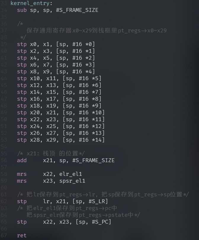
Save the interrupt context(usingkernel_entrymacro)
Jump to the interrupt handler function
Read ARM_Interrupt status register IRQ in LOCAL_SOURCE0
Determine whetherCNT_PNS_IRQInterrupt occurs
If so, reset TimeValue
Return to the el1_irq assembly function
Restore interrupt context
Return to the interrupt site
Interrupt context
- At the moment of interrupt, the CPU state includes:
- PSTATE register
- PC value
- SP value
- x0~x30 registers
- Use a stack frame data structure to describe the interrupt context to be saved (struct pt_regs)
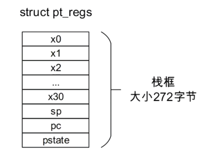
Save interrupt context

Restore interrupt context

Interrupt Experiment 1: Implement generic timer on Raspberry Pi

When the Raspberry Pi firmware starts, it loads the GIC controller by default instead of using Legacy Interrupt, so it can run on QEMU.
Initialize the timer, setcntp_ctl_el0register’senable field to 1
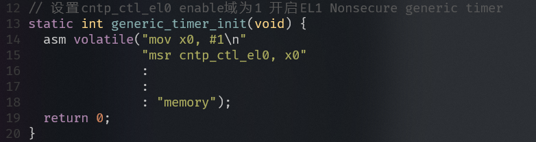
initialize timer to the timer’sTimeValuean initial value, setcntp_tval_el0register

Set cntp_tval_el0 Enable the timer-related interrupts in the Raspberry Pi interrupt controller, setTIMER_CNTRL0in the registerCNT_PNS_IRQto 1

CNT_PNS_IRQ macro definition 
Raspberry Pi TIMER_address of CNTRLx 
set TIMER_CNT of CNTRL0_PNS_IRQ Enable the IRQ interrupt master switch in the PSTATE register

Enable the IRQ interrupt master switch of the PSTATE register A timer interrupt occurs
The CPU jumps to the el1_irq assembly function

Exception vector table 
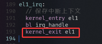
el1_IRQ handling logic Save the interrupt context(usingkernel_entrymacro)

macro definition for saving interrupt context Jump to the interrupt handler function
Read ARM_Interrupt status register IRQ in LOCAL_SOURCE0

ARM_LOCAL_IRQ_SOURCE0 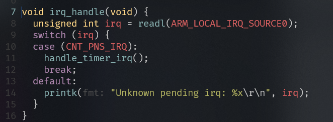
Interrupt forwarding function Determine whetherCNT_PNS_IRQInterrupt occurs
If so, reset TimeValue

- Return to the el1_irq assembly function
- Restore interrupt context
- Return to the interrupt site

Another implementation:
123456789101112131415161718192021222324252627282930313233343536373839404142434445464748495051525354555657585960616263646566676869707172737475767778798081828384858687888990919293949596979899100101102103104105106107108109110 | static inline unsigned long read_cntfrq(void) { unsigned long v; asm volatile("mrs %0, cntfrq_el0" : "=r"(v)); return v;}// ms -> ticksstatic inline unsigned long ms_to_ticks(unsigned int ms) { unsigned long f = read_cntfrq(); return (f / 1000UL) * (unsigned long)ms;}// Set cntp_ctl_Set the el0 enable field to 1 to enable the EL1 Nonsecure generic timerstatic int generic_timer_init(void) { asm volatile("mov x0, #1\n" "msr cntp_ctl_el0, x0" : : : "memory"); return 0;}// Set cntp_ctl_Set the el0 enable field to 0 to disable the EL1 Nonsecure generic timerstatic int generic_timer_deinit(void) { asm volatile("mov x0, #0\n" "msr cntp_ctl_el0, x0" : : : "memory"); return 0;}// %[name] → reference a constraint variable (default width determined by the C variable type)// %w[name] → force reference to a 32-bit register name (e.g., w0, w1)// %x[name] → force reference to a 64-bit register name (e.g., x0, x1)static int generic_timer_reset(unsigned int val) { asm volatile("msr cntp_tval_el0, %x[timer_val]" : : [timer_val] "r"(val) : "memory"); return 0;}static void enable_timer_interrupt(void) { writel(CNT_PNS_IRQ, TIMER_CNTRL0); }static void (*timer_callback)(void) = NULL;void timer_init(unsigned int ms, void (*callback)(void)) { // Initialize timer and cntp_ctl_el0 enable is 1 unsigned int ticks = ms_to_ticks(ms); // ms -> tick generic_timer_reset(ticks); // Enable the interrupt controller and timer-related interrupts enable_timer_interrupt(); timer_callback = callback;}void timer_start(void) { raw_local_irq_disable(); // Disable the PSTATE interrupt master switch to prevent being interrupted during initialization generic_timer_init(); // Enable cntp_ctl_el0.enable=1, start counting raw_local_irq_enable(); // Turn on the PSTATE interrupt master switch to allow interrupt triggering.}void timer_stop(void) { raw_local_irq_disable(); // Turn off the PSTATE interrupt master switch to prevent being interrupted during the disabling process. generic_timer_deinit(); raw_local_irq_enable(); // Restore the PSTATE interrupt master switch.}void timer_reset(unsigned int ms) { unsigned int ticks = ms_to_ticks(ms); // ms -> tick generic_timer_reset(ticks);}void handle_timer_irq(void) { generic_timer_deinit(); if (timer_callback) { timer_callback(); timer_callback = NULL; } printk("Core0 Timer interrupt received\r\n");}void kernel_main(void) { uart_init(); init_printk_done(); printk("Welcome to arm64 mini OS!\r\n"); raw_local_irq_enable(); // Turn on the PSTATE interrupt master switch to allow timer interrupts to trigger. printk("timer test\n"); timer_init(2000, test_function); timer_start(); asm volatile("wfi"); /* my test*/ my_test(); // data_abort does not work in QEMU. // trigger_sync_data_abort(); trigger_sync_instruction_alignment(); while (1) { uart_send(uart_recv()); }} |
Order (recommended order)
cntp_tval_el0← Write timer valueTIMER_CNTRL0.CNT_PNS_IRQ← Enable peripheral interrupt pathPSTATE.I← Disable CPU IRQ master switchcntp_ctl_el0.enable← Start timerPSTATE.I← Enable CPU IRQ master switch
This order ensures Before the CPU enables IRQ, both the peripheral and timer are ready., so once an interrupt triggers, the CPU can immediately receive and handle it.
Before Bare-metal/kernel initialization phase, the timer is not ready yet. If at this time the CPU allows IRQ, it may be interrupted by other peripheral interrupts, resulting in:
- The initialization flow is interrupted, and the configuration registers may only be half-configured.
- Before the timer or peripheral interrupt configuration is complete, an interrupt is already pending → the result is lost interrupts or out-of-order execution.
Interrupt Experiment 2: Using assembly functions to save and restore interrupt context

The key isThe lr register is clobbered when using function calls.


GIC interrupt controller
- Traditional interrupt controllers, such as the legacy interrupt controller on the Raspberry Pi 4B
- Interrupt enable register
- Interrupt disable register
- Interrupt status register
- The traditional way of managing interrupts using simple status registers is becoming increasingly difficult to manage.
- Interrupt sources are becoming increasingly numerous.
- Different types of interrupts, such as inter-core interrupts, interrupt priorities, and software-defined interrupts, etc.

The GIC mainly has two major functional blocks:
- Distributor: All interrupt sources in the system are connected to the distributor. The distributor provides registers to control the attributes of each interrupt, such as priority, state, security, routing information, and enable state. The distributor determines which interrupt to forward to the core through the attached CPU interface.
- CPU Interface: The CPU receives interrupts through it. The CPU interface provides registers to mask, identify, and control the state of interrupts forwarded to that core. Each core in the system has a separate CPU interface.
Interrupt types supported by the GIC
SGI (Software Generated Interrupt), software-generated interrupts (soft interrupts), used to send interrupt signals to other CPU cores
PPI (Private Peripheral Interrupt), private peripheral interrupts, which are exclusive to a specific CPU
SPI(Shared Peripheral Interrupt), shared peripheral interrupts, all CPUs can access this interrupt
LPI (Locality-specific Peripheral Interrupt), location-specific peripheral interrupts,New interrupt types added in GICv3,Message-passing-based interrupt type

Interrupt types supported by the GIC
Interrupt trigger type
Each interrupt type is eitherEdge-triggeredorLevel-sensitive:

by GICD_ICFGRn register control
- Edge-triggered: Triggered when the GIC detects a rising edge on the associated input, and remains pending until cleared.
- Level-sensitive: Only active when the GIC’s associated input is high.
Interrupt number

banked interrupt means that for SGI and PPI, although their IDs are the same across the entire system (for example, the Timer PPI on all cores is ID30), but they are private, each CPU has its own copy, and they do not interfere with each other.
- SGI (0–15): A core triggering SGI0 does not affect SGI0 of other cores.
- PPI (16–31): Core 0’s Timer PPI (e.g., ID30) and Core 1’s Timer PPI (ID30) are independent; they are not shared.
Interrupt numbers 1020~1023 are reserved.

Interrupt priority
Each interrupt priority is set inGICD_IPRIORITYRnthe registers
Priority field width
- Each interrupt priority field is 8 bits.
- The number of priority levels supported by the actual implementation = 2ⁿ, n ∈ [4, 8] (i.e., 16 ~ 256 levels)。
- If the hardware-implemented priority bit width is smaller than 8, for example only 5 bits are implemented, then writing the lower 3 bits is RAZ/WI(read as 0, writes ignored).
Numeric value and priority
- the smaller the value, the higher the priority
- The maximum priority value is implementation-dependent.
- At initialization, by default, all interrupts should be given a medium priority to avoid interrupting system scheduling; common values are 0xa0 or 0x80.
Interrupt status
inactive (Inactive state):The interrupt is in the inactive state.
pending (Pending state):The interrupt is asserted, but is waiting for the CPU to respond to the interrupt.
active (Active state):The CPU has responded to the interrupt and is processing it.
active and pending (Active and pending state):The CPU is responding to the interrupt, but the interrupt source has sent another interrupt.

Interrupt state machine
Interrupt routing

GICD_ITARGETSRn (Interrupt Processor Targets Registers)

GICD_ITARGETSRn registerUsed to configure which CPU the Distributor can route the interrupt to., is a 32-bit register,Each register controls 4 interrupt sources.。
- Each interrupt source is represented by 8 bits, and each bit indicates whether it can be routed to the corresponding CPU.
- byte-accessible
- If a bit is set, it means the interrupt source can be routed to that CPU.
- The routing configuration for the first 32 interrupt sources is set by hardware, RO.
- Interrupts 33 to 1019 can have their routing configured by software, RW.
CorrespondingCalculation method:

Assume m is the interrupt ID, and n is the corresponding register number.
- Relationship between the GICD_ITARGETSRn register and interrupt sources
- Each GICD_ITARGETSRn controls four interrupt sources
- n = m DIV 4
- After calculating n, add the base address offset 0x800 of the GICD_ITARGETSRn register.
- Byte offset of the Priority field
- m MOD 4Used to determine the byte offset corresponding to the target interrupt source
- Offset 0 of the corresponding register [7:0] bits (i.e., the lowest byte), corresponding to interrupt ID m % 4 == 0。
- Offset 1 of the corresponding register [15:8] bits, applicable to m % 4 == 1。
- Offset 2 of the corresponding register [23:16] bits, applicable to m % 4 == 2。
- Offset 3 of the corresponding register [31:24] bits, applicable to m % 4 == 3。
- m MOD 4Used to determine the byte offset corresponding to the target interrupt source
GICD_ITARGETSRn is an array register

GICV2 interrupt controller

- The Distributor registers (GICD_) containsinterrupt set and configuration
- The CPU Interface registers (GICC_) containsCPU-related special settings

The priority and target core of interrupt delivery are configured in the distributor.
Interrupts sent by peripheral devices to the distributor are all in the pending state. The distributor determines the highest-priority pending interrupt, which can be delivered to a core and forwarded to the CPU interface. At the CPU interface, the interrupt is sent to the core in turn, at which point the core takes a FIQ or IRQ exception. The core executes the exception handler in response. The handler reads the interrupt ID from the CPU interface register and begins executing the interrupt service routine. When finished, the handler must write to the CPU interface register to report the end of processing.
The Distributor provides registers that report the current status of different interrupt IDs. In multi-core/multi-processor systems, a single GIC can be shared by multiple cores (up to 8 in GICv2). The GIC provides registers to control the cores associated with SPIs. This mechanism enables the operating system to share and distribute interrupts across cores and coordinate work.
Configuration
The GIC’s register implementations are allexternal memory-map formAll cores can access the common Distributor, but the CPU interface is banked, meaning each core uses the same address to access its own private CPU interface. A core cannot access another core’s CPU interface.
The Distributor contains many registers that you can use to configure the attributes of individual interrupts. These configurable attributes are:
- Interrupt priority(GICD_IPRIORITY), the distributor uses it to determine which interrupt is next forwarded to the CPU interface.
- Interrupt configuration(GICD_ICFGR). This determines whether the interrupt is level-sensitive or edge-sensitive. Not applicable to SGI.
- A target core for an interrupt(GICD_ITARGETSR). This determines which cores the interrupt can be routed to. Only applicable to SPI.
- Interrupt enable or disable state(GICD_ISENABLER / GICD_ICENABLER). Only those interrupts enabled in the distributor are eligible to be routed to the CPU interface when they are in the pending state.
- Interrupt security (GICD_IGROUPR) determines whether the interrupt is assigned to secure or non-secure.
- Interrupt status。
The Distributor also provides a priority mask, through which interrupts below a certain priority can be prevented from reaching the core. The distributor uses it when determining whether a pending interrupt can be forwarded to a particular core. The CPU interface on each core helps fine-tune interrupt control and handling.
Initialize:
The Distributor and CPU interface are both disabled at reset. The GIC must be initialized after reset before it can deliver interrupts to the core.
In the Distributor, software must configure priority, target core, security, and enable individual interrupts. Then it must be through its control register (GICD_CTLR) enable distributor。
For each CPU interface, software must configure the priority mask and priority preemption. Each CPU interface itself must be enabled through the control register (GICC_CTLR) enabled.
Before the CPU processes an interrupt, software configures the CPU to be ready to accept a valid interrupt vector from the interrupt vector table, clears the interrupt mask bits in PSTATE, and sets up routing control.
The entire interrupt mechanism in the system can be disabled by disabling the Distributor. Interrupt delivery to an individual core can also be disabled by disabling its CPU interface. Individual interrupts can also be disabled (or enabled) in the distributor.
For an interrupt to reach a core, the individual interrupt, the distributor, and the CPU interface must all be enabled. The interrupt also needs sufficient priority, i.e., higher than the core’s priority mask.
Interrupt handling
When the core accepts an interrupt, it jumps to the top-level interrupt vector table and begins execution. The top-levelinterrupt handler reads a register from the CPU interface to obtain the interrupt ID。
Reading the register not only returns the interrupt ID, but also causes the interrupt to be marked as active in the distributor. Once the interrupt ID is known (identifying the interrupt source), the top-level handler can schedule a device-specific interrupt handler to service the interrupt.
When the interrupt handler finishes execution, the top-level handler writes the same interrupt ID to the End of Interrupt (EoI) register in the CPU interface block, indicating the end of interrupt handling.
In addition to removing the active state, making the final interrupt state Inactive or pending (if the state was active and pending), this enables the CPU interface to forward more pending interrupts to the core. This ends the handling of a single interrupt.
There may be multiple interrupts waiting for service on the same core, but the CPU interface can only signal one interrupt at a time. The top-level interrupt handler can repeat the above sequence until it readsthe special interrupt ID value 1023,indicating that there are no more pending interrupts on this core. This special interrupt ID is calledspurious interrupt identifier (Spurious Interrupt ID). The spurious interrupt ID is a reserved value and cannot be assigned to the system.When the top-level handler reads the spurious interrupt ID, it can complete execution and prepare the core to resume the task that was being executed before the interrupt.
The Generic Interrupt Controller (GIC) typically manages inputs from multiple interrupt sources and distributes them to IRQ or FIQ.
Interrupt state timing diagram

M and N represent two interrupts respectively, Input represents the interrupt signal, State represents the interrupt state machine, and nFIQCPU[n] represents the FIQ signal connected to the CPU core.
Assume M and N are both SPI interrupts, and N has a higher priority than M.
GICv2 registers

Some registers are indexed by interrupt number. For example, certain bits are used to describe the attributes of an interrupt number, and the same register can have multiple instances, such as the GICD_ISENABLERn register, which is used to enable a particular interrupt number. ‘n’ indicates that there are n such registers.


Calculation method: Calculate the corresponding register based on the interrupt number.

For some registers, there is a note:
A register bit corresponding to an unimplemented interrupt is RAZ/WI.
RAZ = Read-As-Zero
If you read this register bit, the return value is always 0, even if you have written other values.
WI = Write-Ignored
If you write data to this bit,the hardware will ignore, it will not change, nor will it report an error.
GICD_CTLR
Distributor Control Register


GICD_ITARGETSRn
Interrupt Processor Targets Registers, see the interrupt routing section.
GICD_TYPER (Interrupt Controller Type Register)
Describes the capabilities and configuration parameters of this GIC, such as how many interrupts, how many CPU interfaces, whether certain features are supported, and so on.


GICD_ICFGRn
Interrupt Configuration Registers
The GIC is used to configureinterrupt trigger typeregisters
eachGICD_ICFGRnYes 32-bit register。

Distribution method
Each interrupt requires 2 bit (Int_config) to describe, soOne register can configure 16 interrupts。
the
nregister (ICFGRn) The corresponding interrupt range is:1中断 ID = n*16 ~ (n*16 + 15)
Int_config field encoding
According to the ARM GICv2 TRM (Table 4-18):

For PPI(Private Peripheral Interrupt) and SPIfor (Shared Peripheral Interrupt)
| Int_config[1:0] | meaning |
|---|---|
| 0b00 | Level-sensitive |
| 0b10 | Edge-triggered |
| 0b01 / 0b11 | Reserved |
GICD_ISENABLERn
Interrupt Set-Enable Registers
responsible forenabling interrupt forwarding
GICD_ISENABLERnYes32-bit register
each
GICD_ISENABLERncontrols 32 interrupt sources。
GICD_ISENABLERn Write 1 → Enables the corresponding interrupt (allows the Distributor to forward it to the CPU interface)
Write 0 → No effect
Read → Shows whether an interrupt is currently enabled (1=enabled, 0=disabled)
Based on the interrupt numberCalculate n for GICD_ISENABLERn

GICD_ICENABLERn
Interrupt Clear-Enable Registers
- W1C (Write 1 to Clear), disables an interrupt (prevents distribution to the CPU)


GICD_ISACTIVERn
Interrupt Set-Active Registers
- W1S (Write 1 to Set), software canmanually mark an interrupt state as active。


GICD_ICACTIVERn
Interrupt Clear-Active Registers
W1C (Write 1 to Clear), clears the active state of the interrupt.
It is somewhat similar to EOI (End of Interrupt), but EOI is a CPU interface register, and can only be used by the current CPU to perform the “interrupt service complete” action on the interrupts it has received;
ICACTIVERnBefore Distributor, software canglobally force clear the active bit of a certain interrupt。


GICD_IPRIORITYRn
Interrupt Priority Registers
used forsetting the priority of each interrupt
Each interrupt occupies 8 bits
A 32-bit register manages 4 interrupts


Address calculation:

GICC_CTLR
CPU Interface Control Register


GICC_PMR
Interrupt Priority Mask Register
The priority mask register of the CPU interface, it determines which priority interrupts the CPU can receive。
- Only interrupts with priority value ≤ PMR can be received by the CPU.
- Note: The priority of GIC is the smaller the value, the higher the priority。


Usage example: Suppose your GIC implementation has 8-bit priority:
- if
GICC_PMR = 0xff- The CPU receives interrupts of all priorities (the most common initialization setting).
- if
GICC_PMR = 0xa0- Only receive Priority value ≤ 0xa0 interrupts, and those with a lower priority will be masked.
- if
GICC_PMR = 0x0- Only receive the highest priority (0) interrupt, all others are masked.
GICC_IAR
Interrupt Acknowledge Register
When the CPU receives an IRQ signal, software needs to read the current from this register. ID of the pending interrupt, and confirm which IRQ it is.

| Bits | Name | meaning |
|---|---|---|
| [9:0] | INTID | Interrupt ID (0~1019 indicates a valid interrupt number) |
| [12:10] | CPUID | Identifies the CPU that triggered the interrupt (useful in multi-core systems) |
| [31:13] | Reserved | Reserved, reads as 0 |
GICC_EOIR
End of Interrupt Register
After completing interrupt processing, software must write to this register to tell the GIC: ‘This IRQ has been handled, the active state can be cleared, and subsequent identical interrupts are allowed to trigger again.’

| Bits | Name | meaning |
|---|---|---|
| [9:0] | INTID | Interrupt ID (must match the interrupt number read from IAR) |
| [12:10] | CPUID | For SGI, write the CPU ID read from IAR; for other interrupts, write 0 |
| [31:13] | Reserved | Reserved, write 0 |
GIC400 of Raspberry Pi 4B

- ARM Core interrupts:
- Core n HP timer IRQ
- Core n V timer IRQ
- Legacy FIQn
- Core n PS timer IRQ
- Core n PNS timer IRQ (PPI ID 30)
- Legacy IRQn
- ARM local interrupts
- ARM Mailbox IRQs
- Core 0 PMU IRQ
- Core 1 PMU IRQ
- Core 2 PMU IRQ
- Core 3 PMU IRQ
- AXIERR IRQ
- Local timer IRQ
- 16 ARMC peripheral interrupts
- 64 VC peripheral interrupts
- 51 PCI-related peripheral interrupts
Accessing GIC-400 registers
- Base address of GIC-400 on Raspberry Pi 4B

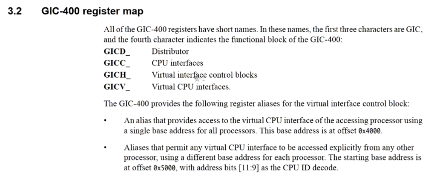
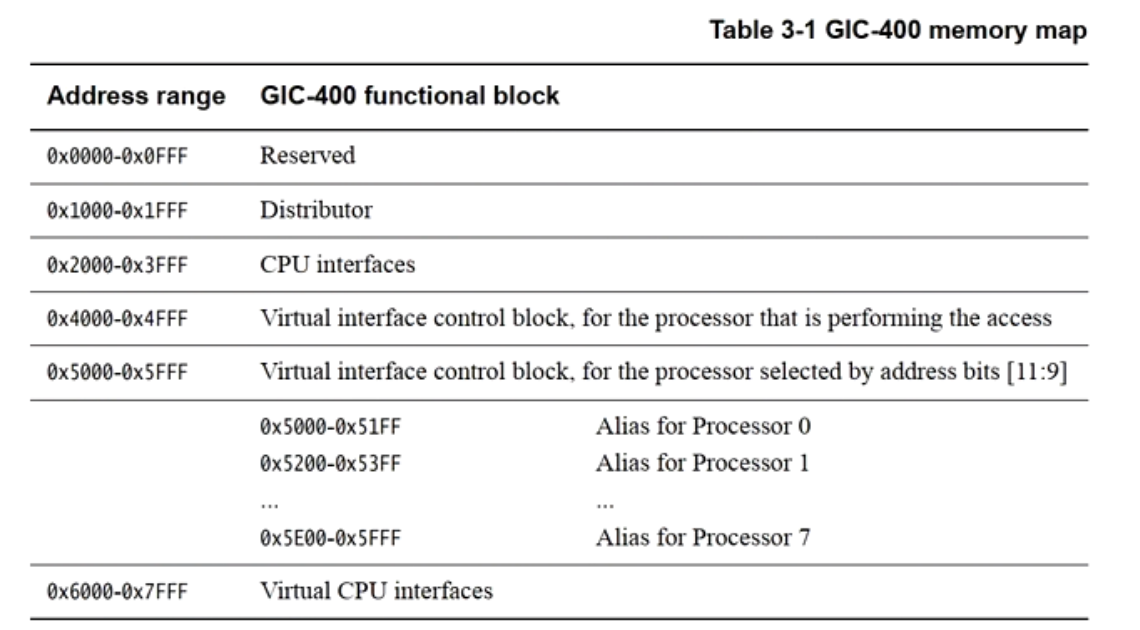
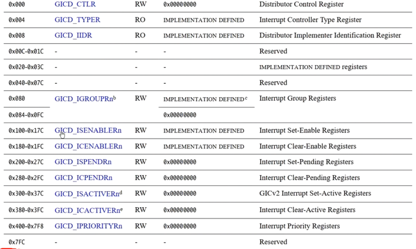
Access: Raspberry Pi GIC400’sbase address+ GIC-400 memory map offset + register offset
GIC400 initialization flow
- Set the base addresses of the distributor and CPU interface register groups
- ReadGICD_TYPERregister, calculate the maximum number of interrupt sources supported by the current GIC.
- Initialize distributor
- Disable distributor, setGICD_CTLR(This step can be skipped because it is already disabled at reset.)
- Set SPI interrupt routing
- The routing of the first 32 interrupts is fixed by the GIC chip, so first readGICD_ITARGETSRnthe preceding value to get all CPUs that can be routed
- will SPI (Shared Peripheral Interrupt) interrupt routing is set to distribute the interrupt to all routable CPUs, because SPI interrupts are shared interrupts, set the SPI’sGICD_ITARGETSRn
- Set the trigger type of SPI interrupts, e.g., level-triggered, setGICD_ICFGRn
- Deactivate and disable all SPI interrupt sources
- Enable SGI interrupts (0-15), which will be used by SMP
- Enable distributor, setGICD_CTLR
- Initialize CPU interface
- Set default interrupt priority for the first 32 interrupt sources, setGICD_IPRIORITYRn
- SetGICC_PMR, set the interrupt priority mask level
- Enable CPU interface, setGICC_CTLR
Register interrupt
- Initialize peripherals
- Find the interrupt number of this peripheral in the GIC-400. For example, the interrupt number of the PNS timer is 30.
- SetGICD_ISENABLERnregister to enable this interrupt number
- Enable device-related interrupts, for example, the generic timer on the Raspberry Pi, you need to enable the ARM_TIMER in the LOCAL register_the relevant enable bit in the CNTRL0 register
- Enable the I bit in the CPU’s PSTATE.
Interrupt response
- Interrupt occurs
- Exception vector table
- Jump to the GIC interrupt function, gic_handle_irq()
- ReadGICC_IARregister, get the interrupt number
- Perform the corresponding interrupt handling according to the interrupt number. For example, if the read interrupt number is 30, it indicates the PNS generic timer, then jump to the generic timer’s handler function.
GIC interrupt experiment 1: Implement generic timer

GIC-400 initialization
- SetdistributorandCPU interfacebase address of the register group
123456789101112131415161718192021222324252627282930313233343536373839404142 | // Directly using n / 4 or n / 16 will get the register index.// Then multiply by 4 in the address calculation (each register is 4 bytes).int gic_init(void);void gic_enable_irq(int irq); |
- ReadGICD_TYPERregister, calculate the maximum number of interrupt sources supported by the current GIC.

Initializedistributor

Initialize distributor 
gic_distributor_init Initialize CPU interface

gic_cpu_init Enable PNS_TIMER_IRQ routing

- Test


GIC Interrupt Experiment 2: Implementing System Timer on Raspberry Pi

GICv3 Interrupt Controller
What improvements does GICv3 have over GICv2?
- GICv3 is compatible with GICv2
- Supports more CPUs, >8
- Supports message-based interrupts (Message Signaled Interrupt,MSI)
- SupportsITS(Interrupt Translation Service) service
- Supports more hardware interrupt numbers, >1020
- To better support the ARMv8 exception model, it supportsinterrupt groups(Interrupt grouping)
- To optimize access latency,provides a system register method to access the CPU Interface
Interrupt types supported by GICv3
- Private Peripheral Interrupt(PPI)
- PPI refers to interrupts specific to a local CPU, such as internal CPU timers. Different CPUs can use the same PPI interrupt number.
- PPIs can be in Group 0 and Group 1
- Can be edge-triggered or level-sensitive
- Shared Peripheral Interrupt(SPI)
- SPI is typically used for peripheral interrupts and can be routed to any CPU.
- SPIs can be in Group 0 and Group 1
- Can be edge-triggered or level-sensitive
- Software Generated Interrupt(SGI)
- SGI is typically a software-triggered interrupt used for inter-core communication, such as IPIs (Inter-Processor Interrupts).
- SGIs can only be edge-triggered
- New:Locality-specific Peripheral Interrupt(LPI)
- In Non-secure Interrupt Group 1
- Edge-triggered
- Uses ITS service
- Has no active state
- Message-based interrupt

Wired interrupts and message-based interrupts


- Both SPI and LPI support message-based interrupts.
- SPI message-based interrupts do not require ITS; instead, writing GICD_SETSPI_NSR the interrupt number to a register triggers the interrupt.
- LPI message-based interrupts need to go through the ITS.
Interrupt number allocation

Interrupt state machine
- Inactive Inactive state
- Pending The interrupt has been triggered, but has not yet been acknowledged by the CPU.
- Active The interrupt is acknowledged and handled by the CPU.
- Active & Pending When an interrupt is being acknowledged and handled by the CPU, if the same interrupt triggers again, the new interrupt is set to active & pending.
- LPIThere are no active and active & pending states.
Question: What if, while the GIC is acknowledging an interrupt, another identical interrupt triggers? What happens then?
There are two cases to consider:
- If the GIC is acknowledging the first interrupt, i.e., the first interrupt is in the active state, and then the second identical interrupt triggers, the second interrupt’s state becomes active & pending, thus avoiding losing the interrupt.
- If the first interrupt is still in the pending state, and another identical interrupt arrives, they will merge into one.

Interrupt affinity routing hierarchy (Affinity routing)
- GICv3 supports 4-level routing
- Level 0 faces the redistributor


GIC-500 interrupt affinity routing

- GIC-500 supports two-level affinity routing
- Level 0 is the core
- Level 1 is the cluster
- GIC-500 supports up to 128 cores and 32 clusters.
0.0.0.1 represents core 1 in cluster 0.
0.0.1.1 represents core 1 in cluster 1.
- Interrupt groups and security modes.
- ARMv8 supports secure and non-secure modes.
- GICv3 supports interrupt delivery from EL1 to EL3, so each interrupt source needs to set the corresponding interrupt group and security mode.
- Group0 is used for EL3.
- Secure Group1: used for Trust OS on EL2.
- Non-secure Group1: used for VMM or OS.

Group0 uses FIQ, Group1 uses IRQ or FIQ depending on the situation.


Example

Note: Whether an interrupt is routed to EL3 depends on the FIQ and IRQ fields of the SCR_EL3 register.
- In non-secure mode:
- Non-secure Group1 interrupts are handled directly in the Rich OS.
- Secure Group1 and Group0 FIQ interrupts are routed to EL3.
- In secure mode.
- Secure Group1 IRQ interrupts are handled directly in the Trusted OS.
- Non-secure Group1 and Group0 FIQ interrupts are routed to EL3.
Special interrupt numbers.

Use case 1 for interrupt 1021.

- CPU is running Trusted OS in secure mode, and an interrupt from a non-secure OS arrives. It needs to trap to EL3 via FIQ to handle it.
- CPU traps to the secure monitor at EL3. The secure monitor reads the IAR register and gets 1021, indicating that this interrupt is expected to be handled in non-secure mode, so it switches to the Rich OS in non-secure mode.
- The CPU switches to the Rich OS in non-secure mode to handle this interrupt.
Use case 2 for interrupt 1021.

- CPU is running Trusted OS in secure mode, and an interrupt from a non-secure OS arrives. It needs to trap to EL3 via FIQ to handle it. However, because SCR_EL3.FIQ=0, it can only be handled in EL2.
- The Trusted OS at EL2 executes an SMC system call to trap to EL3.
- The Secure Monitor reads the IAR register and reads the value 1021, indicating that this interrupt is intended to be handled in non-secure mode, and switches to the Rich OS in non-secure mode.
- The CPU switches to the Rich OS in non-secure mode to handle this interrupt.
GICC and ICC
**ICC(Interrupt Controller CPU interface)**Specifically in the GIC the interface part that directly interacts with the CPU, via System Registers Access
Why are the CPU interface registers of GICv2 calledGICC_*, while GICv3’s are calledICC_*?
The core of the answer lies in:GICv2 and GICv3 have undergone a fundamental change in the implementation of the CPU interface. — from memory-mapped I/O (MMIO) transformed to System Registers. ARM uses naming differences to clearly distinguish the two architectures.
Interrupt priority
- GICv3 supports 8-bit priority, up to 256 levels.
- When two security modes are supported, it supports at least 32 interrupt priorities and at most 256.
- When one security mode is supported, it supports at least 16 interrupt priorities.
- Interrupt priority
- The smaller the value, the higher the interrupt priority. 0 indicates the highest priority, 255 indicates the lowest priority, idle priority.
GICR_IPRIORITYR<n>Set PPI and SGI interrupt priorities.GICD_IPRIORITYR<n>Set SPI interrupt priority.- The LPI configuration table stores the interrupt priority of the LPI.
Interrupt Priority Group Register (ICC_BPR0_EL1/ICC_BPR1_EL1)
- Each interrupt in the GIC has a 8-bit priority value (priority field), the smaller the value, the higher the priority (e.g., 0x00 is the highest priority, 0xFF is the lowest).
- When the CPU Interface decides whether to preempt the currently executing interrupt , it compares the priorities of the new interrupt and the current interrupt.
But the GIC does not simply compare the entire 8-bit value — it does so by Binary Point Register(BPR) dividing the priority into two parts:
| field | meaning |
|---|---|
| Group Priority | the high-order part, used to determine whether preemption is allowed |
| Subpriority | the low-order part, used only for ordering when the group priorities are the same |
ICC_BPR0_EL1: used for Group 0 interruptICC_BPR1_EL1: used for Group 1 interrupt
Note: the grouping for group1 and group0 is slightly different.

Interrupt priority threshold and running interrupt priority
- Interrupt threshold
- register:ICC_PMR_EL1(Priority Mask Register)
- PMR determines the priority threshold of the target CPU. The GIC sends an interrupt to the CPU only when the priority of a pending interrupt is higher than this interrupt priority threshold.
- PMR being 0 means all interrupts sent to the CPU are masked.
- Running priority
- register:ICC_RPR_EL1(Running Priority Register)
- Read-only register, returns theGroup Priority of the highest-priority interrupt being processed on the current CPU。
Interrupt priority preemption
- GICv3Supports interrupt preemption, when an interrupt priority simultaneously satisfies the following conditions
- priority is higher than the CPU interface’s priority threshold PMR
- Group priority is higher than the running priority being processed
GICv3 internal architecture

- Distributor: priority queuing, dispatches SPI and SGI to the redistributor
- Redistributor: connects to the CPU interface. One redistributor per CPU.
- CPU interface: sends interrupts to the CPU, acknowledges interrupts, etc.
- ITS: Interrupt Translation Service, converts LPI interrupt requests to interrupt numbers and sends them to the redistributor.
ITS service (Interrupt Translation Service)
- ITS function: converts the device (device_id)'s Event_ID is converted into:
- hardware interrupt number (INTID)
- target redistributor
- ITS translation process
- Use Device_ID to query the device table
- Use Event_ID to query the Interrupt Translation Table
- Physical interrupt number INTID
- interrupt collection number
- Use ICID to query the Collection table to obtain the target redistributor
- ITS five tables
- Interrupt Configuration Table (Configuration Table)
- Interrupt Pending Table (Pending Table)
- Device Table
- Interrupt Translation Table(ITT)
- Collection Table


Configuration table and pending table
Interrupt Configuration TableUsed to store the priority and enable bit of each LPI interrupt
- Each table entry occupies 8 bits
- Configuration table base address: GICR_PROPBASER.Physical_Address
- Number of entries: 2^(GICR_PROPBASER.IDbits)

Interrupt Configuration Table

- Interrupt pending Used to indicate the pending state of each LPI interrupt
- Each table entry occupies 1 bit
- Each redistributor has an interrupt pending table

Creation of Device Table
Device Table is created by OS software
- Allocate memory and create the table
- Set the base address of the table to GITS_BASER.Physical_Address
The important parameters of the Device Table are in
GITS_BASER<n>the registers- Table type: GITS_BASER.Type
- Size of table entry: GITS_BASER.Entry_Size (8 bytes)
- Size of each page in the table: GITS_BASER.Page_Size(eg, 64KB)
- Whether a level-2 page table is required: GITS_BASER_Indirect
- Set table base address: GITS_BASER.Physical_Address
- Number of table entries needed: 2^(device_id bit width), device_id bit width is in GITS_TYPER.devbits
Device Table supports one-level or two-level tables
The content of the Device Table entry is determined by:
- Software sends commands to the hardware via the command queue, and the hardware populates the table entries.
- Map deviceID to the ITT table via the MAPD command.


- Device Table entries are called DTEs and are used to point to the ITT table.

- ITT entries are called ITEs, which describe the relationship between EventID and the final physical interrupt ID.

Creation of the Interrupt Translation Table
- ITT entries are used to map EventID -> physical interrupt number INTID and ICID
- Key parameters of ITT
- ITT entry size: GITS_TYPER.ITT_entry_size (e.g., 16 bytes)
- Number of ITT entries: the number of vectors requested when allocating interrupts.
- Base address of the ITT table: allocated by the OS
- The content of ITT entries is determined by:
- Software sends commands to hardware through the command queue, and the hardware completes them.
- Map deviceID to the ITT table via the MAPD command.
Creation of the Collection Table
Collection Table entries are used to map:ICID -> redistributor
This table does not need to be allocated in memory.
The content of Collection Table entries is determined by:
- Software sends commands to hardware through the command queue, and the hardware completes them.
- Software informs: the physical address of the redistributor or GICR._TYPER.Processor_Number
- Map ICID -> redistributor via the MAPC command.
- During GIC initialization, traverse all redistributors and call the MAPC command to initialize.
1234567
gic_smp_init()-> 遍历所有present CPU()-> gic_starting_cpu()-> its_cpu_init()-> its_cpu_init_collections()-> its_cpu_init_collection()-> its_send_mapc()发送MAPC命令初始化collection table
CTE, the entry of the Collection table

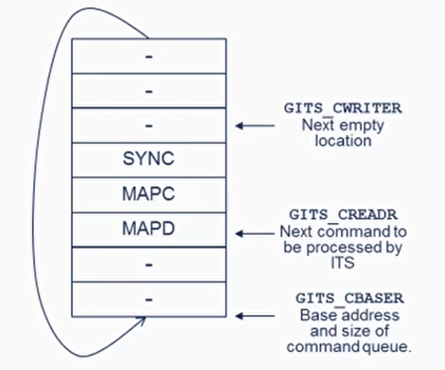
ITS Command Queue
- Three registers related to the command queue
- GITS_CBASER: specifies the size and base address of the command queue; the base address must be 64KB aligned, and the size must be an integer multiple of 4KB.
- GITS_CREADR: the next command to be processed by the ITS
- GITS_CWRITER: the next command to be written
- Commonly used commands
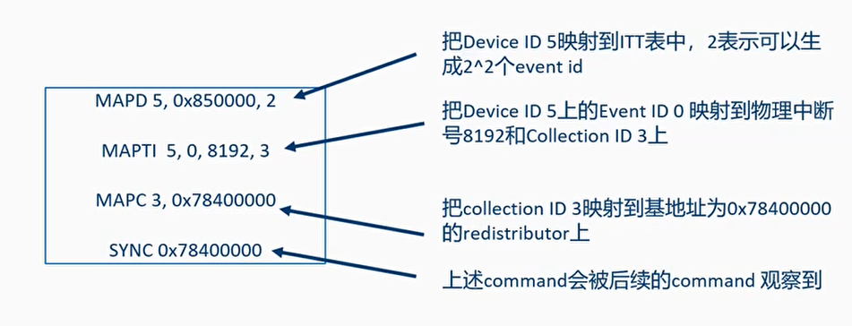
- MAPD: maps device ID to the ITT table
MAPD <DeviceID>, <ITT_addr>, <size>
- MAPI: maps eventid and deviceid to the ITT
MAPI <DeviceID>, <EventID>, <Collection ID>
- MAPTI: maps eventid, deviceid, and hardware interrupt number to the ITT
MAPTI <DeviceID>, <EventID>, <INTID>, <Collection ID>
- MAPC: maps collection id to the target redistributor
MAPC <Collection ID>, <Target Redistributor>
- MAPD: maps device ID to the ITT table
Example
Assume a device has Device ID 5, and we want to map Event ID=0 to physical interrupt number 8192, with the ITT table base address 0x850000. The corresponding Collection ID is 3, and the corresponding target redistributor’s physical address is 0x78400000.
In the Linux kernel, vector is often used to represent event ID
Implementation of ITS in Linux

IRQ domain (interrupt controller domain)
- The possibility of multiple levels of interrupt controllers in a system
- Traditional interrupt controller - GIC
- Can be abstracted as interrupt controllers: GIC, ITS, GPIO, etc.
- Virtual interrupt controller, platform irqdomain
- IRQ Domain is viewed as a software abstraction of the IRQ Controller

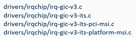
ITS driver framework


API for creating MSI interrupts


Example of using MSI interrupts in a platform device - SMMUv3

Flowchart for platform device requesting MSI interrupt allocation

Flowchart for PCI device MSI interrupt allocation


How do I/O devices trigger interrupts?
For GICv3 interrupt control, an I/O device needs to write the event ID to the GITS_TRANSLATER register to trigger an MSI interrupt.

The Linux kernel encapsulates a struct msi_msg data structure, which includes the address of this register and the data to be written.
12345 | struct msi_msg { u32 address_lo; u32 address_hi; u32 data;}; |
In irq_The chip’s ops has an ITS_irq_compose_msi_msg callback function, used to fill this msi_msg, that is, the GITS_the physical address of the TRANSLATER register is written into msi_in the msg->address field
When the device driver uses platform_msi_domain_alloc_irqs() to register MSI, it will from the msi_from the msg data structure, obtain the GITS_the physical address of the TRANSLATER register and eventID, then write to the IO device’s own registers (e.g., SMMU_EVENTQ_IRQ_CFG0 and CFG1).
When the device wants to trigger MSI, it automatically writes eventID into its own register to trigger the interrupt.
Take SMMU as an example:

ITS Debug Tips
- The latest QEMU supports ITS. You can use QEMU + Linux kernel to single-step debug ITS and MSI
- Add “irq to the kernel command line_gic_v3_its.dyndbg=+pflmt irqdomain.dyndbg=+pflmt” to enable the relevant dynamic debug:

- You can in its_domain_ops callback add “dump_stack()” to print the calltrace of the calling functions