Timeline
Timeline
2025-10-16
init
This article introduces the exception model in the ARM64 architecture, including the definition of exception levels (EL0~EL3), exception-related terminology, the classification of synchronous and asynchronous exceptions, and the hardware and software processing flow of exception entry and return. The article details the state saving automatically completed by the CPU hardware when an exception occurs (e.g., PSTATE is saved to SPSR_ELx, return address saved to ELR_ELx, update ESR_ELx, etc.), and the operating system needs to set up the exception vector table and exception handling functions. At the same time, the article summarizes three cases of exception return addresses (asynchronous exceptions, non-system-call synchronous exceptions, system calls), and introduces the routing rules for exception handling, including that synchronous exceptions can be handled at the current EL, asynchronous exceptions can be routed to EL1/EL2/EL3, and HCR_The influence of EL2 and SCR_EL3 registers on routing configuration. Finally, the article cites Table D1-10 in the ARMv8.6 specification, illustrating the target privilege levels of exceptions under different configurations.
Reference documents:

Exception levels of ARM64 (Exception Level)
- EL0 Non-privileged mode, e.g., applications
- EL1 Privileged mode, e.g., OS kernel
- EL2 Virtualization monitor, e.g., hypervisor
- EL3 Secure mode, e.g., secure monitor
Terminology (Exception terminology)
- Taking an exception: The CPU responds to an exception (traps to exception handling)
- Returning from an exception: Return from an exception
- Exception levels: Exception level
- Precise exception: Precise exception
- Synchronous and asynchronous exception: Synchronous and asynchronous exceptions
Types of exceptions
- Synchronous exception
- System calls, svc, hvc, SMC, etc.
- Exceptions caused by the MMU
- SP and PC alignment checks
- Unallocated instructions
- Unallocated instruction opcodes
- Instructions that require a higher privilege level than the current exception level.
- Disabled instructions.
- Any instruction when the PSTATE.IL field is set
- Debug exception
- Asynchronous exception
- IRQ interrupt
- FIQ interrupt
- SError(System error)
Synchronous exceptions are predictable and reproducible exceptions triggered by the execution of a specific instruction; asynchronous exceptions are unpredictable exceptions triggered by external events (such as interrupts).
Exception Entry
Process state or PSTATE is an abstraction of process state information
- When an exception occurs,CPU hardwarewhat does it do?
- PSTATE is saved to SPSR_ELx (The Saved Program Status Register)
- The return address is saved to ELR_ELx
- The DAIF fields of the PSTATE register are all set to 1, which effectively disables debug exceptions, system errors (SError), IRQ interrupts, and FIQ interrupts.
- The ESR_ELx (Exception Syndrome Register) is updated, containing the reason for the synchronous exception or SError.
- SP is switched to SP_ELx
- Switch to the corresponding EL, then jump to the exception vector table for execution.
- After an exception occurs,operating systemwhat does it need to do?
The operating system needs to set up the exception vector table, so that the CPU jumps to the appropriate exception vector table entry based on the type of exception that occurred.
Each entry in the exception vector table stores a branch instruction (e.g.,
b <handler>), which jumps to the corresponding exception handler.
The Exception Syndrome Register (ESR_ELn) contains information that allows the exception handler to determine the cause of the exception. It is updated only for synchronous exceptions and SError, not for IRQ or FIQ, because these interrupt handlers typically obtain status information from the Generic Interrupt Controller (GIC) registers.
Exception return
- The operating system executes aneretstatement
- Restore the PC pointer from the ELR_ELx (Exception Link Register) register.
- Restore the processor state from the SPSR_ELx (The Saved Program Status Register) register.

Exception return address
- Two return address registers
- x30: return address of the subroutine. Use the ret instruction to return.
- ELR_ELx: exception return address. Use the eret instruction to return.
- ELR_ELxThe register stores the exception return address.
- For asynchronous exceptions, the return address is the next instruction when the interrupt occurs, or the first instruction that was not executed.
- For synchronous exceptions that are not system calls, the return address is the instruction that triggered the synchronous exception.
- For system calls, it returns the next instruction after the svc/hvc instruction.
Asynchronous exception (interrupt)
The hardware has already set ELR to the next instruction to be executed,
eretJust go back and continue executing; no additional modification is needed.
Synchronous exception (not a system call)
The hardware sets ELR to the instruction that triggered the exception
If you have fixed the cause of the exception (e.g., a page fault), theneretit will directly re-execute this instruction.
If you want to skip it (do not retry), you need to manuallyELR_ELx += 4
system call(svc)
The hardware sets ELR to the next instruction after svc, so
eretit will directly return to the next instruction.
Exception handling routing
When an exception occurs at a specific “Exception Level (EL)”, to which Exception Level should the CPU jump to handle it?
- When an exception occurs, it can behandled at the current EL, or it can be handled at a higher EL.
- EL0 cannot be used to handle exceptions.
- Synchronous exceptions can be handled at the current EL., for example, when a synchronous exception occurs at EL1.
- ForAsynchronous exceptions can be routed to EL1, EL2, or EL3 for handling., which requires configuringHCR(Hypervisor Configuration Register) andSCRregisters related to the Secure Configuration Register.
- If the exception is caused by an instruction fetch at EL0, it is treated as an EL1 exception, unless the HCR_EL2.TGE bit is set to 1 and the processor is in a non-secure state, in which case it is treated as an EL2 exception.

Refer to Table D1-10 in ARMv8.6.
- SCR_EL3: Secure Configuration Register
- HCR_EL2: Hypervisor Configuration Register
The table in this figure (Table D1-10) isthe interrupt/exception routing rule table for the ARM architecture when EL3 (Secure Monitor Mode) and EL2 (Virtualization Monitor Mode) are implemented simultaneously., and is mainly used to define the target privilege level (EL0~EL3) to which the processor ultimately jumps after an interrupt (IRQ/FIQ) or exception (such as an Abort exception) is triggered under different system states (register configurations).

- Row 1: SCR=0, NS EEL2a=0, EA IRQ FIQ=0, RW=0
- Input conditions: Security configuration is default (SCR=0), non-secure EL2 exception entry is disabled (NS EEL2a=0), no active interrupts/exceptions (EA IRQ FIQ=0), read/write permission is 0; HCR TGE and E2H are arbitrary values (X).
- Routing result:
- Triggered from EL0: jumps to “FIQ IRQ Abt” (i.e., the native handling entry for the corresponding interrupt/exception, not intercepted by a higher EL);
- Triggered from EL1: same as EL0, jumps to “FIQ IRQ Abt”;
- Triggered from EL2:
n/a(Not applicable, because when NS EEL2a=0, EL2 does not enable this scenario); - Triggered from EL3: jump to ‘C’ (usually refers to the exception handling entry in Secure state; in ARM architecture, ‘C’ often represents the secure-related default target).
- Row 2: SCR=0, NS EEL2a=0, EA IRQ FIQ=0, RW=1
- Input conditions: Only RW (read/write permission) changes from 0 to 1; the rest is the same as Row 1.
- Routing result:
- Triggered from EL0/EL1: jump to ‘EL1’ (i.e., the exception is intercepted and handled by EL1 (kernel mode), rather than the native interrupt entry, because RW=1 corresponds to higher-privilege kernel handling logic);
- Triggered from EL2:
n/a(same as Row 1, EL2 not enabled); - Triggered from EL3: jump to ‘C’ (Secure state entry unchanged).
- Row 3: SCR=0, NS EEL2a=0, EA IRQ FIQ=1
- Input conditions: EA IRQ FIQ=1 (an active interrupt/exception is triggered), other configurations are the same as the previous two rows; HCR TGE and E2H are arbitrary values.
- Routing result:
- Triggered from EL0/EL1: jump to ‘EL3’ (active interrupt/exception is intercepted by the highest security level EL3, consistent with the ARM security architecture logic that ‘high-priority exceptions are handled by EL3’);
- Triggered from EL2:
n/a(EL2 not enabled); - Triggered from EL3: jump to ‘EL3’ (an exception triggered by EL3 itself is handled within EL3, without jumping to other levels).
- Row 4: SCR=0, NS EEL2a=1, EA IRQ FIQ=0, HCR TGE=0, E2H=0, RW=0
- Input conditions: NS EEL2a=1 (Non-secure EL2 exception entry enabled), no active interrupt/exception (EA IRQ FIQ=0), virtualization mode disabled (HCR TGE=0), EL2 does not intercept EL1 exceptions (E2H=0).
- Routing result:
- Triggered from EL0: jump to ‘FIQ IRQ Abt’ (native interrupt entry);
- Triggered from EL1: jump to ‘FIQ IRQ Abt’ (EL2 does not intercept, because E2H=0);
- Triggered from EL2: jump to ‘C’ (an exception triggered by Non-secure EL2 is routed to the Secure state entry ‘C’);
- Triggered from EL3: jump to ‘C’ (handled internally in Secure state, target unchanged).
Stack selection
- Each exception level EL has a corresponding stack pointer register SP_ELx.
- SP_EL0, SP_EL1, SP_EL2, SP_EL3
- **The stack must be 16-byte aligned.**The hardware can detect whether the stack pointer is aligned.
- When an exception occurs and jumps to the target exception level, the hardware automatically selects SP_ELx.
- The operating system is responsible for allocatingand ensuring that the stack corresponding to each exception level EL is available.
Execution mode
Execution mode for exception handling
- When an exception occurs, it switches to a higher EL. Which mode does this EL run in? AArch64 or AArch32
- HCR_EL2.RW(Hypervisor Configuration Register) Records which mode EL1 should run in.
- 1 means aarch64
- 0 means aarch32
- HCR_EL2.RW(Hypervisor Configuration Register) Records which mode EL1 should run in.

- After an exception occurs, the execution mode can change.
- An aarch32 application is running. At this time, an interrupt arrives, and it may jump to EL1 in the aarch64 execution state to handle the interrupt.
Execution mode for exception return
- When returning from an exception, the SPSR register (Saved Program Status Register) records:
- Which EL to return to? SPSR.M[3:0]
- The execution mode of the target EL to return to?SPSR.M[4]
- 0 means aarch64
- 1 means aarch32

| M[3:0] | Target mode | Description |
|---|---|---|
0000 | EL0t | EL0, using SP_EL0 |
0100 | EL1t | EL1, using SP_EL0 |
0101 | EL1h | EL1, using SP_EL1 |
1000 | EL2t | EL2, using SP_EL0 |
1001 | EL2h | EL2, using SP_EL2 |
1100 | EL3t | EL3, using SP_EL0 |
1101 | EL3h | EL3, using SP_EL3 |
Experiment 1: Switch to running in EL1

Hint
To switch from EL2 to EL1, you need to do the following things:
Set the HCR_EL2 (Hypervisor Configuration Register) register. The most important thing is the RW field at bit 31, which indicates which execution state EL1 will run in, AArch32 or AArch64.(Similarly, the execution state of EL2 is determined by SCR_EL3.)
- HCR_EL2 is a General System Control Register.

HCR_EL2 
HCR_EL2.RW Set SCTLR_EL1 (System Control Register), to set the endianness and disable the MMU.

SCTLR_EL1.EE 
SCTLR_EL1.E0E 
SCTLR_EL1.M Set the SPSR_EL2 (Saved Program Status Register) register, set the mode M field to EL1h, and also disable all DAIF in PSTATE.
- SPSR_ELxBelongs toSpecial-purpose Register

SPSR_EL2 
SPSR_EL2.M 
PSTATE.DAIF at EL2 
SPSR_EL1 
SPSR_EL.M
| M[3:0] | Target mode | Description |
|---|---|---|
0000 | EL0t | EL0, using SP_EL0 |
0100 | EL1t | EL1, using SP_EL0 |
0101 | EL1h | EL1, using SP_EL1 |
1000 | EL2t | EL2, using SP_EL0 |
1001 | EL2h | EL2, using SP_EL2 |
1100 | EL3t | EL3, using SP_EL0 |
1101 | EL3h | EL3, using SP_EL3 |

Set the exception return register elr_el2 so that it returns to the el1_entry assembly function.
Executeeret
(3, 4 are actually the classic steps of an exception return, from EL2 back to EL1.)
First, determine which exception level to jump to based on the current exception level.

Note that the elr_el2 register must be set before executing eret.

Exception vector table (Exception vectors)
Each exception level EL has its own exception vector table, except EL0.
The base address of the exception vector table needs to be set to VBAR_ELx(Vector Base Address Register) the registers
VBAR_EL1 register:

VBAR_ELx Bits 0-10 are reserved, thereforeThe address is aligned to 2K.
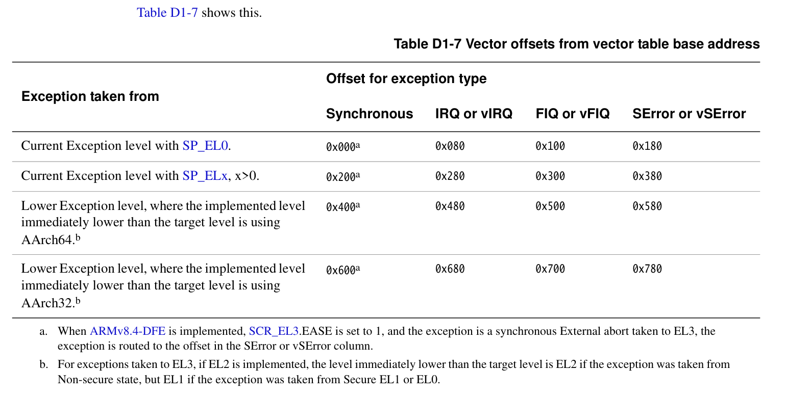
Row (Exception taken from)
Defines the “current execution state” when an exception is triggered, divided into 4 types of scenarios:
- Current Exception level with SP_EL0: The current exception level uses
SP_EL0stack pointer (e.g., when an exception is triggered while using the user-level stack pointer at EL1). - Current Exception level with SP_ELx, x>0: The current exception level uses
SP_ELx(x≥1, e.g., EL1 usesSP_EL1, EL2 usesSP_EL2etc., kernel-level stack pointer) when an exception is triggered. - Lower Exception level(AArch64): Triggered from a lower exception level, and the “lower level” is in AArch64 execution state (e.g., when switching from EL0/EL1 to a higher EL, and the original level is 64-bit mode).
- Lower Exception level(AArch32): Triggered from a lower exception level, and the “lower level” is in AArch32 execution state (e.g., switching from EL0/EL1 in 32-bit mode to a higher EL).
- Current Exception level with SP_EL0: The current exception level uses
Column (Offset for exception type)
Classified by exception type, corresponding to different offsets:
- Synchronous: Synchronous exception (e.g., instruction execution errors, software-triggered exceptions, etc., occurring synchronously with the instruction stream).
- IRQ or vIRQ: Normal interrupt (IRQ) or virtual interrupt (vIRQ, in virtualization scenarios).
- FIQ or vFIQ: Fast interrupt (FIQ, usually higher priority) or virtual fast interrupt (vFIQ, virtualization scenarios).
- SError or vSError: System error (SError, e.g., serious errors like bus errors) or virtual system error (vSError, virtualization scenarios).
Offset value (e.g., 0x000, 0x080, etc.): Based on the combination of row (trigger state) and column (exception type), the offset relative to the vector table base address is given. The processor can find the entry address of the exception handler by base address + offset.

- Overall structure of the exception vector table
Before AArch64 EL1 In execution levels at and above, the exception vector table (Vector Table) is stored at VBAR_ELx (Vector Base Address Register) register pointed to address.
This table contains a total of 4 “blocks” (blocks), corresponding to different exception sources:
- From the current SP (SP0) triggered exceptions
- From the current SP (SPx) triggered exceptions (x≠0, e.g., SP_EL1)
- From a lower privilege level using AArch64 (e.g., EL0) exceptions
- From a lower privilege level using AArch32 (e.g., EL0) exceptions
Each block also contains 4 exception types:
- Synchronous exception (synchronous exceptions, e.g., SVC instructions, data access exceptions)
- IRQ (normal interrupt)
- FIQ (fast interrupt)
- SError (system error, usually a hardware exception)
So in total:
4 blocks × 4 exception types = 16 table entries
Size of each entry
ARMv8-A specifies:
- The size of each entry is fixed at 128 bytes.(0x80) (size of 32 instructions).
- 16 entries × 128 bytes = 2048 bytes = 2KB。
- So the size of the entire vector table is 2KB。
In other words, the exception vector table must be 2KB alignedregion.
The exception vector table actually consists of 4 groups of 4 entries.
Exception handling in the Linux 5.0 kernel
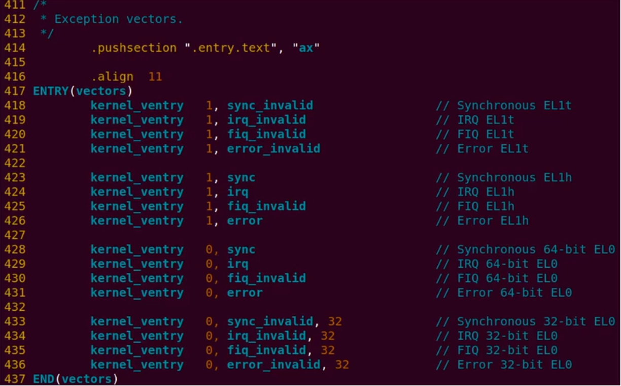
.align 11 is to make the exception vector table2K-aligned
kernel_ventry is a macro, the simplified code is as follows

align 7 means aligning by 2 to the power of 7, which is 128 bytes.
The sub instruction subtracts an S from the stack pointer sp._FRAME_SIZE, where S_FRAME_SIZE is called the register frame size, which is the size of the struct pt_regs data structure.
“\()” means concatenation.
For example: when an EL1 IRQ interrupt occurs, this statement becomes “b el1_irq”.
kernel_entryIt is the first-level entry that the exception vector table jumps to, and its responsibilities are:
- Save context: Save the CPU state (general-purpose registers) to the stack.
- Set up stack frame: Prepare stack space for the exception handling function (C code).
- Switch Stack(If needed): For example, when entering kernel mode from user mode, the stack needs to be switched to the kernel stack.
- Call the C-layer exception dispatch function。
Take the FIQ occurring at EL1 as an example


Save exception context
- stack frame: In the Linux kernel, a … is defined. struct pt_regs A data structure that describes the arrangement of registers saved on the kernel stack, typically used to save exception context.
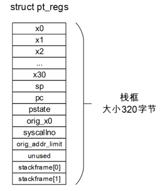
orig_x0, syscallno, orig_addr_limit, unused, stackframe[0], stackframe[1] are all things defined and saved by software

Experiment 2: Build an exception vector table and create a synchronous exception

FAR Fault Address Register (at EL1)
Its function is:
- when Synchronous Exception occurred when, the processor will [handle] the exception-causing… virtual addresswrite to
FAR_ELxIn the corresponding register. EL1It corresponds to the kernel mode (operating system layer), soFAR_EL1What is saved is Virtual address when an exception occurs at EL1。
Common Scenarios
- Page Fault
If the CPU triggers an exception when accessing a non-existent or illegal virtual address,FAR_EL1This address will be saved, and the kernel can use it to decide whether to allocate a new page or kill the process. - Alignment Fault (unaligned access exception)
If the access address does not conform to alignment rules,FAR_EL1that address is also saved. - Watchpoint/Breakpoint exception
FAR_EL1may also be used to store the address that triggered the exception.
Related registers
ESR_EL1(Exception Syndrome Register)
Save the exception’s cause code(such as page fault, permission error, misalignment, etc.).FAR_EL1
Save the specific virtual address。
entry.S
123456789101112131415161718192021222324252627282930313233343536373839404142434445464748495051525354555657585960616263646566676869707172737475767778798081828384858687888990919293949596979899100 | #define BAD_SYNC 0#define BAD_IRQ 1#define BAD_FIQ 2#define BAD_ERROR 3 .macro inv_entry el, reason // Save exception context, not yet implemented // kernel_entry el mov x0, sp mov x1, #\reason mrs x2, esr_el1 b bad_mode .endm // Exception vector table .macro vtentry label .align 7 b \label .endm/** ARM64The exception vector table occupies a total of2048bytes,divided into four groups,each entry occupies128bytes* .align 11indicates that when2048Alignment*/.align 11.global vectorsvectors:/* Current EL with SP0* using the current exception level SP_EL0 an exception is triggered(For example EL1 use SP_EL0)*/ vtentry el1_sync_invalid vtentry el1_irq_invalid vtentry el1_fiq_invalid vtentry el1_error_invalid/* Current EL with SPx* the system is currently running inEL1used whenEL1the stack pointerSP* indicates that an exception occurred in the kernel mode of the system* currently only implementsIRQinterrupt*/ vtentry el1_sync_invalid vtentry el1_irq_invalid vtentry el1_fiq_invalid vtentry el1_error_invalid/* Lower EL using AArch64* user-modeaarch64program exception occurs*/ vtentry el0_sync_invalid vtentry el0_irq_invalid vtentry el0_fiq_invalid vtentry el0_error_invalid/* Lower EL using AArch32* in user modeaarch32program exception occurs*/ vtentry el0_sync_invalid vtentry el0_irq_invalid vtentry el0_fiq_invalid vtentry el0_error_invalidel1_sync_invalid: inv_entry 1, BAD_SYNCel1_irq_invalid: inv_entry 1, BAD_IRQel1_fiq_invalid: inv_entry 1, BAD_FIQel1_error_invalid: inv_entry 1, BAD_ERRORel0_sync_invalid: inv_entry 0, BAD_SYNCel0_irq_invalid: inv_entry 0, BAD_IRQel0_fiq_invalid: inv_entry 0, BAD_FIQel0_error_invalid: inv_entry 0, BAD_ERROR// occupies two bytesstring_test: .string "t"// because string_test causes it to be not 4-byte aligned.global trigger_alignmenttrigger_alignment: ldr x0, =0x80002 ldr x1, [x0] ret |
kernel.cdefined in

Beforekernel_maintriggered intrigger_alignment
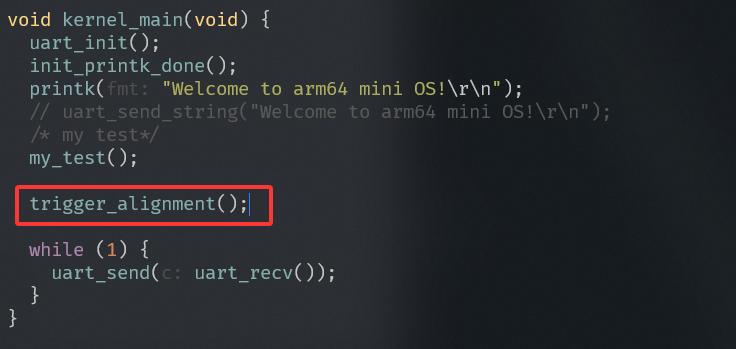
Beforeboot.Sset up the exception vector table in

Experiment 3: Fix the bug: Find the instruction that triggers the exception on Raspberry Pi 4


This instruction loads the value at the address PC+MY_LABEL into x6
Equivalent to:
1 | x6 = *(PC-relative 地址 + MY_LABEL) |
For LDR Xt,The target address must be 8-byte aligned (because Xt is a 64-bit register)
It can be changed to w6, which only requires 4-byte alignment, because MY_LABEL is defined as 0x20
Exception analysis
ESR_ELx (Exception Syndrome Register)
ESR_ELx is updated only for synchronous exceptions and SError, not for IRQ or FIQ, because these interrupt handlers typically obtain status information from the registers of the Generic Interrupt Controller (GIC).

- The ESR register contains a total of four fields (domains).
- Bits 32~63 are reserved bits.
- Bits 26~31 areException Class (EC for short), this fieldIndicates the type of exception that occurred, and is also used toIndex the ISS field
- Bit 25, IL, indicates the instruction length of the synchronous exception instruction, Instruction Length
- Bit 0~24,ISS (Instruction Specific Syndrome) specific exception instruction encoding. This exception instruction encoding table depends on the different exception types,Different exception types have different encoding formats

Common exception type corresponding encodings

The first indicates an instruction exception from a lower exception level, the second indicates an instruction exception at the current exception level

Encoding method of the ISS field


FAR (Fault Address Register)

FAR registerStores the virtual address at the time the exception occurred
Experiment 4: Parsing data abort information


esr.h
12345678910111213141516171819202122232425262728293031323334353637383940414243444546474849505152535455565758596061626364656667686970717273747576777879808182838485868788899091929394959697 | /* Unallocated EC: 0x02 *//* Unallocated EC: 0x09 - 0x0B *//* Unallocated EC: 0x0d *//* Unallocated EC: 0x0F - 0x10 *//* Unallocated EC: 0x14 *//* Unallocated EC: 0x19 - 0x1E *//* Unallocated EC: 0x23 *//* Unallocated EC: 0x27 *//* Unallocated EC: 0x29 - 0x2B *//* Unallocated EC: 0x2D - 0x2E *//* Unallocated EC: 0x36 - 0x37 *//* Unallocated EC: 0x39 *//* Unallocated EC: 0x3B *//* Unallocated EC: 0x3D - 0x3F */ |
Function: Parse the value of the ESR_ELx register to facilitate exception handling.
Structure:
- High 6 bits → EC(Exception Class)
- IL, ISV → instruction length/validity
- ISS → Instruction Specific Syndrome
- FSC → data access exception code
- WNR, EA, CM → access attributes
kernel.c
123456789101112131415161718192021222324252627282930313233343536373839404142434445464748495051525354555657585960616263646566676869707172737475767778798081828384858687888990919293949596979899100101102103104105106107108109110111112113 | static const char *const bad_mode_handler[] = {"Sync Abort", "IRQ", "FIQ", "SError"};static const char *data_fault_code[] = { [0] = "Address size fault, level0", [1] = "Address size fault, level1", [2] = "Address size fault, level2", [3] = "Address size fault, level3", [4] = "Translation fault, level0", [5] = "Translation fault, level1", [6] = "Translation fault, level2", [7] = "Translation fault, level3", [9] = "Access flag fault, level1", [10] = "Access flag fault, level2", [11] = "Access flag fault, level3", [13] = "Permission fault, level1", [14] = "Permission fault, level2", [15] = "Permission fault, level3", [0x21] = "Alignment fault", [0x35] = "Unsupported Exclusive or Atomic access",};static const char *esr_get_dfsc_string(unsigned int esr) { return data_fault_code[esr & 0x3f];}static const char *esr_class_str[] = { // GCC extension, indicating that the array indices from 0 to ESR_ELx_EC_MAX all initialized to "UNRECOGNIZED // EC"。 [0 ... ESR_ELx_EC_MAX] = "UNRECOGNIZED EC", [ESR_ELx_EC_UNKNOWN] = "Unknown/Uncategorized", [ESR_ELx_EC_WFx] = "WFI/WFE", [ESR_ELx_EC_CP15_32] = "CP15 MCR/MRC", [ESR_ELx_EC_CP15_64] = "CP15 MCRR/MRRC", [ESR_ELx_EC_CP14_MR] = "CP14 MCR/MRC", [ESR_ELx_EC_CP14_LS] = "CP14 LDC/STC", [ESR_ELx_EC_FP_ASIMD] = "ASIMD", [ESR_ELx_EC_CP10_ID] = "CP10 MRC/VMRS", [ESR_ELx_EC_CP14_64] = "CP14 MCRR/MRRC", [ESR_ELx_EC_ILL] = "PSTATE.IL", [ESR_ELx_EC_SVC32] = "SVC (AArch32)", [ESR_ELx_EC_HVC32] = "HVC (AArch32)", [ESR_ELx_EC_SMC32] = "SMC (AArch32)", [ESR_ELx_EC_SVC64] = "SVC (AArch64)", [ESR_ELx_EC_HVC64] = "HVC (AArch64)", [ESR_ELx_EC_SMC64] = "SMC (AArch64)", [ESR_ELx_EC_SYS64] = "MSR/MRS (AArch64)", [ESR_ELx_EC_IMP_DEF] = "EL3 IMP DEF", [ESR_ELx_EC_IABT_LOW] = "IABT (lower EL)", [ESR_ELx_EC_IABT_CUR] = "IABT (current EL)", [ESR_ELx_EC_PC_ALIGN] = "PC Alignment", [ESR_ELx_EC_DABT_LOW] = "DABT (lower EL)", [ESR_ELx_EC_DABT_CUR] = "DABT (current EL)", [ESR_ELx_EC_SP_ALIGN] = "SP Alignment", [ESR_ELx_EC_FP_EXC32] = "FP (AArch32)", [ESR_ELx_EC_FP_EXC64] = "FP (AArch64)", [ESR_ELx_EC_SERROR] = "SError", [ESR_ELx_EC_BREAKPT_LOW] = "Breakpoint (lower EL)", [ESR_ELx_EC_BREAKPT_CUR] = "Breakpoint (current EL)", [ESR_ELx_EC_SOFTSTP_LOW] = "Software Step (lower EL)", [ESR_ELx_EC_SOFTSTP_CUR] = "Software Step (current EL)", [ESR_ELx_EC_WATCHPT_LOW] = "Watchpoint (lower EL)", [ESR_ELx_EC_WATCHPT_CUR] = "Watchpoint (current EL)", [ESR_ELx_EC_BKPT32] = "BKPT (AArch32)", [ESR_ELx_EC_VECTOR32] = "Vector catch (AArch32)", [ESR_ELx_EC_BRK64] = "BRK (AArch64)",};static const char *esr_get_class_string(unsigned int esr) { return esr_class_str[esr >> ESR_ELx_EC_SHIFT];}void parse_esr(unsigned int esr) { unsigned int ec = ESR_ELx_EC(esr); printk("ESR info:\n"); printk(" ESR = 0x%08x\n", esr); printk(" Exception class = %s, IL = %u bits\n", esr_get_class_string(esr), (esr & ESR_ELx_IL) ? 32 : 16); if (ec == ESR_ELx_EC_DABT_LOW || ec == ESR_ELx_EC_DABT_CUR) { printk(" Data abort:\n"); if ((esr & ESR_ELx_ISV)) { printk(" Access size = %u byte(s)\n", 1U << ((esr & ESR_ELx_SAS) >> ESR_ELx_SAS_SHIFT)); printk(" SSE = %lu, SRT = %lu\n", (esr & ESR_ELx_SSE) >> ESR_ELx_SSE_SHIFT, (esr & ESR_ELx_SRT_MASK) >> ESR_ELx_SRT_SHIFT); printk(" SF = %lu, AR = %lu\n", (esr & ESR_ELx_SF) >> ESR_ELx_SF_SHIFT, (esr & ESR_ELx_AR) >> ESR_ELx_AR_SHIFT); } printk(" SET = %lu, FnV = %lu\n", (esr >> ESR_ELx_SET_SHIFT) & 3, (esr >> ESR_ELx_FnV_SHIFT) & 1); printk(" EA = %lu, S1PTW = %lu\n", (esr >> ESR_ELx_EA_SHIFT) & 1, (esr >> ESR_ELx_S1PTW_SHIFT) & 1); printk(" CM = %lu, WnR = %lu\n", (esr & ESR_ELx_CM) >> ESR_ELx_CM_SHIFT, (esr & ESR_ELx_WNR) >> ESR_ELx_WNR_SHIFT); printk(" DFSC = %s\n", esr_get_dfsc_string(esr)); } else { printk("Not supported yet\n"); }}void bad_mode(struct pt_regs *regs, int reason, unsigned int esr) { printk("Bad mode for %s handler detected, far:0x%x esr:0x%x - %s\n", bad_mode_handler[reason], read_sysreg(far_el1), esr, esr_get_class_string(esr)); parse_esr(esr);}extern void trigger_sync_data_abort(void);extern void trigger_sync_instruction_alignment(void); |
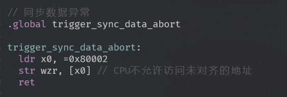
Code that triggers data exception: