
Timeline
Timeline
2026-07-02
init
This article introduces the working principle of the IPCC (Inter-Processor Communication Controller) hardware module in STM32MP157, discusses the process of realizing signal notification between Cortex-A7 and Cortex-M4 cores through shared memory and hardware interrupt mechanisms, and summarizes the channel allocation, software framework application, and related register configuration of IPCC.
IPC( Inter -Process Communication, Inter-Process Communication) refers to the interaction of data between two processes (in a broad sense, including processes of heterogeneous cores), which is achieved through the inter-processor communication controller IPCC(Inter-Process Communication controller , IPC controller). IPCC belongs to the hardware part and is used for signal exchange between two CPUs. The mailbox depends on IPCC. The IPCC hardware module of STM32MP157 has 6 bidirectional channels, each channel is divided into two sub-channels, so the 6 bidirectional channels have a total of 12 sub-channels. The figure shows the structural block diagram of communication between the A7 core and the M4 core through IPCC.
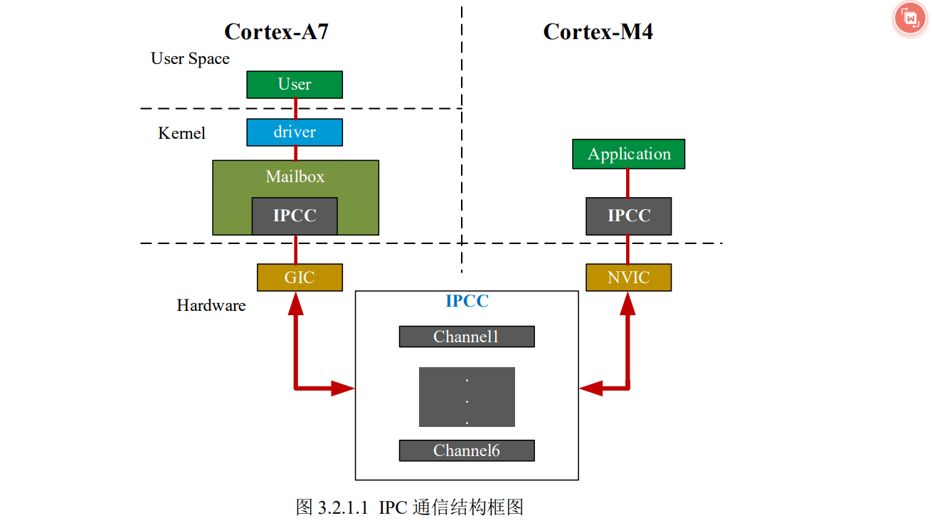
When a data packet is placed in shared memory, the CPU needs to interrupt or ‘notify’ the other CPU that there is a new data packet to be processed in the shared memory. The other CPU processes it after receiving the signal, which is accomplished using the IPCC hardware interrupt mechanism.。
The interrupt controller of the A7 core is GIC, and the interrupt controller of the M4 core is NVIC. The role of IPCC is like a sentry, controlling when data can be received and when data can be sent. The entire process is controlled by IPCC.
IPCC only provides a mechanism for information exchange between processors; it does not have a data transmission function., that is to say,the data to be exchanged between processorsis not transmitted in the IPCC,but is transmitted in the shared memory.。
IPCC Channels
The working modes of the 6 IPCC communications can be divided into simplex, half-duplex, and full-duplex:
- There are 6 channels from CPU1 to CPU2 (P1_TO_P2 sub-channel, P1 represents CPU1, P2 represents CPU2)
- There are 6 channels from CPU2 to CPU1 (P2_TO_P1 sub-channel, P1 represents CPU1, P2 represents CPU2)
As shown in the table below, in the IPCC communication model officially configured by ST, these 6 channels are used as different software frameworks, among which:
- Channel 3 is in simplex mode and is used as the RemoteProc framework, through which the main processor can load the firmware of the coprocessor and control the lifecycle of the coprocessor;
- Channel 2 is in full-duplex mode and is used as the RPMsg framework, which is used to transmit messages from A7 to M4;
- Channel 1 is in full-duplex mode and is used as the RPMsg framework, which is used to transmit messages from M4 to A7.
| Channel | Mode | Usage | Software client framework: Cortex-A7 (Non-secure) | Software client framework: Cortex-M4 |
|---|---|---|---|---|
| Channel 1 | Full-duplex | RPMsg transmission from Cortex-M4 to Cortex-A7: 1. Cortex-M4 uses this channel to indicate a message is available 2. Cortex-A7 uses this channel to indicate the message has been processed | RPMsg framework | OpenAMP |
| Channel 2 | Full-duplex | RPMsg transmission from Cortex-A7 to Cortex-M4: 1. Cortex-A7 uses this channel to indicate a message is available 2. Cortex-M4 uses this channel to indicate the message has been processed | RPMsg framework | OpenAMP |
| Channel 3 | Simplex | Cortex-M4 shutdown request | RemoteProc framework | CprocSync cube utility |
| Channel 4/5/6 | Unused |
Simplex communication: Refers to signals being transmitted in only one direction, capable of only sending or receiving
Half-duplex communication: Signals can be transmitted in both directions, but at any given moment, only sending or receiving is allowed (Single-wire bus and I2C are both half-duplex communications)
Full-duplex communication: Full-duplex communication refers to the simultaneous transmission of data in both directions
As can be seen, in the framework configured by ST:
- The RemoteProc software framework solves the problem of remote processor lifecycle
- The RPMsg software framework solves the problem of inter-core communication
These two are the concerns in multi-core processor communication!
Under the Linux kernel, ST has already ported the RemoteProc and RPMsg software frameworks. In the OpenAMP library used by M4, there are also corresponding RemoteProc and RPMsg software frameworks. M4 mainly relies on the existing software frameworks in the OpenAMP library to communicate with A7.
Note: To facilitate the main core’s control over the coprocessor, the OpenAMP framework was designed on the Linux side. At the same time, to be compatible with the Linux-side OpenAMP framework, the relevant M4 vendors also designed an OpenAMP framework. The two can be interfaced, but there are still some differences, even though they share the same name.
The A7 and M4 of STM32MP157 actually transfer data through Channel 1 and Channel 2:

IPCC Registers
There are 8 registers related to IPCC. The register area is divided into two regions, with each processor occupying one region to prevent read-write access conflicts. As shown in the table below, the first 4 registers are occupied by Processor 1, and the last 4 registers are occupied by Processor 2.
IPCC provides dedicated interrupts for the processors. Each processor has its own status mask register bits, and set or clear register bits for each channel.
| Register | Description | Bit (n represents 1~6) |
|---|---|---|
| IPCC_C1CR | Enable/Disable Processor 1 TX channel free interrupt/RX channel occupied interrupt | TXFIE、RXOIE |
| IPCC_C1MR | Mask/Unmask Processor 1 TX channel X free interrupt/RX channel X occupied interrupt | CHnFM、CHnOM |
| IPCC_C1SCR | Processor 1 TX/RX Channel X status bit Set/Clear | CHnS、CHnC |
| IPCC_C1TOC2SR | Channel occupied/free | CHnF |
| IPCC_C2CR | Enable/Disable Processor 2 TX channel free interrupt/RX channel occupied interrupt | TXFIE、RXOIE |
| IPCC_C2MR | Mask/Unmask Processor 2 TX channel X free interrupt/RX channel X occupied interrupt | CHnFM、CHnOM |
| IPCC_C2SCR | Processor 2 TX/RX Channel X status bit Set/Clear | CHnS、CHnC |
| IPCC_C2TOC1SR | Channel occupied/free | CHnF |
IPCC_C1CR
IPCC Processor 1 Control Register
| 31 | 30 | 29 | 28 | 27 | 26 | 25 | 24 | 23 | 22 | 21 | 20 | 19 | 18 | 17 | 16 |
|---|---|---|---|---|---|---|---|---|---|---|---|---|---|---|---|
| Res | Res | Res | Res | Res | Res | Res | Res | Res | Res | Res | Res | Res | Res | Res | TXFIE |
| rw |
| 15 | 14 | 13 | 12 | 11 | 10 | 9 | 8 | 7 | 6 | 5 | 4 | 3 | 2 | 1 | 0 |
|---|---|---|---|---|---|---|---|---|---|---|---|---|---|---|---|
| Res | Res | Res | Res | Res | Res | Res | Res | Res | Res | Res | Res | Res | Res | Res | RXOIE |
| rw |
- Bits 17~31 and bits 1~15, reserved bits, must be kept at the reset value.
- Bit 16, TXFIE: Processor 1 Transmit (TX) channel free interrupt enable bit, associated with IPCC_C1TOC2SR, when this bit is:
- 1: Enable Processor 1 Transmit (TX) channel free interrupt;
- 0: Disable Processor 1 Transmit (TX) channel free interrupt.
- Bit 0, RXOIE: Processor 1 Receive (RX) channel occupied interrupt enable bit, associated withIPCC_C2TOC1SR, when this bit is:
- 1: Enable Processor 1 Receive (RX) channel occupied interrupt;
- 0: Disable Processor 1 Receive (RX) channel occupied interrupt.
IPCC_C1MR
IPCC Processor 1 Mask Register
| 31 | 30 | 29 | 28 | 27 | 26 | 25 | 24 | 23 | 22 | 21 | 20 | 19 | 18 | 17 | 16 |
|---|---|---|---|---|---|---|---|---|---|---|---|---|---|---|---|
| Res | Res | Res | Res | Res | Res | Res | Res | Res | Res | CH6FM | CH5FM | CH4FM | CH3FM | CH2FM | CH1FM |
| rw | rw | rw | rw | rw | rw |
| 15 | 14 | 13 | 12 | 11 | 10 | 9 | 8 | 7 | 6 | 5 | 4 | 3 | 2 | 1 | 0 |
|---|---|---|---|---|---|---|---|---|---|---|---|---|---|---|---|
| Res | Res | Res | Res | Res | Res | Res | Res | Res | Res | CH6OM | CH5OM | CH4OM | CH3OM | CH2OM | CH1OM |
| rw | rw | rw | rw | rw | rw |
Bits 22 to 31 and bits 6 to 15, reserved bits, must be kept at reset value.
Bits 16 to 21,CH1FM~CH6FM, Processor 1 transmit (TX) channel X idle interrupt mask bit, associated with IPCC_C1TOC2SR.CHxF, when this bit is:
- 1: transmit (TX) channel X idle interrupt is masked;
- 0: transmit (TX) channel X idle interrupt is not masked.
Bits 0 and 5,CH1OMCH6OM, Processor 1 receive (RX) channel X occupied interrupt mask bit, associated withIPCC_C2TOC1SR.CHxF, related to, when this bit is:
- 1: receive (RX) channel X occupied interrupt is masked;
- 0: receive (RX) channel X occupied interrupt is not masked.
IPCC_C1SCR
IPCC Processor 1 Status Set/Clear Register
| 31 | 30 | 29 | 28 | 27 | 26 | 25 | 24 | 23 | 22 | 21 | 20 | 19 | 18 | 17 | 16 |
|---|---|---|---|---|---|---|---|---|---|---|---|---|---|---|---|
| Res | Res | Res | Res | Res | Res | Res | Res | Res | Res | CH6FM | CH5FM | CH4FM | CH3FM | CH2FM | CH1FM |
| rw | rw | rw | rw | rw | rw |
| 15 | 14 | 13 | 12 | 11 | 10 | 9 | 8 | 7 | 6 | 5 | 4 | 3 | 2 | 1 | 0 |
|---|---|---|---|---|---|---|---|---|---|---|---|---|---|---|---|
| Res | Res | Res | Res | Res | Res | Res | Res | Res | Res | CH6OM | CH5OM | CH4OM | CH3OM | CH2OM | CH1OM |
| rw | rw | rw | rw | rw | rw |
- Bits 22 to 31 and bits 6 to 15, reserved bits, must be kept at reset value.
- Bits 16 to 21, CH1S~CH6S, Processor 1 transmit (TX) channel X status set bit, associated withIPCC_C1TOC2SR.CHxF , related to, when this bit is set:
- 1: Processor 1 transmit (TX) channel X status bit is set, which sets CHnF to 1, indicating the channel is occupied;
- 0: No action.
- Bits 0 to 5, CH1C~CH6C, Processor 1 receive (RX) channel X status clear bit, associated withIPCC_C2TOC1SR.CHxF, associated with, when this bit is set:
- 1: Processor 1 receive (RX) channel X status bit is cleared;
- 0: No action
IPCC Functional Description
The IPCC controls processor communication through interrupts, known as Inter-Processor Interrupts (IPI). There are two interrupt lines on each processor, which are:
- One for RX channel occupied (transmitting processor publishes data);
- One for TX channel idle (receiving processor reads communication data).
Each channel has an interrupt mask:
- Channel occupied mask (bit CHnOM);
- Channel free mask (bit CHnFM).
In the context of computers, microcontrollers, or hardware peripherals (such as communication controllers like DMA, Mailbox, IPCC, etc.),“Mask” means to “turn off” or “filter out” an interrupt signal, preventing it from being reported to the CPU。
Each sub-channel has two operating modes:
- Simplex mode (each channel has its own communication data storage location);
- Half-duplex mode (a single channel associated with a bidirectional communication data information storage location).
The communication data is located in shared memory (note that shared memory is not part of the IPCC), and for each communication, the IPCC module provides achannel status flag bit CHnF(n can take values 1~6, representing the corresponding channel):
- When CHnF=0, it indicates that the associated channel is free(it can also be considered that the communication data has been read by the receiving processor, and the channel is now in a free state),at this time, the sending processor can occupy this channel to send data;
- When CHnF=1, it indicates that the associated channel has been occupied(i.e., the communication data has been published by the sending processor),at this time, the receiving processor can access the channel to read the data.
IPCC provides a non-blocking signaling mechanism for channel management:
- Message availability interrupt;
- Channel flow control (e.g., generating a TX channel free interrupt is called flow on, and when the channel is occupied, it is called flow off).
Applications benefit from message exchange based on non-blocking interrupts and channel flow control for inter-core communication, and each sub-channel has a transmission direction:
- Sent from CPU1 and received by CPU2;
- Or sent from CPU2 and received by CPU1.
Simplex transmit mode
The figure below shows a schematic diagram of the IPCC simplex transmit mode.
- When the channel status flag indicates channel occupied (CHnF=1), it is because the receiver has not released the channel from the previous message. At this time, the channel idle interrupt is unmasked, and then it waits for the TX idle interrupt.
- Once the receiver releases the channel, a channel idle interrupt (stream on) is generated. When the channel idle interrupt is generated, the channel idle interrupt is masked, and the message can be written to the data buffer. Subsequently, the channel status flag is set to occupied, which triggers the channel occupied interrupt on the receiver side.

Simplex reception mode
The following figure shows a schematic diagram of the IPCC simplex transmission mode. When a channel occupied interrupt is generated, the receiver determines which channel is occupied and masks the corresponding channel occupied interrupt. Subsequently, data can be read from the shared memory. Once the data is read, the channel status flag CHnF is cleared (CHnF=0), and the channel occupied interrupt is unmasked.

Half-duplex transmission mode
The following figure shows a schematic diagram of the IPCC half-duplex transmission mode.
The half-duplex process allows a message to be transmitted from the sender to the receiver using a single shared buffer, and then the response (Response pending) is sent back from the receiver to the sender.
Sender data transmission process:
- The software variable response pending=1 indicates that the sender is waiting for the receiver’s response.
- response pending=0 indicates that the receiver’s response has been received.
First, the sender checks the channel status flag. If the channel status flag indicates that the channel is occupied (CHnF=1), meaning the receiver has not yet sent a response to the previous message, the sender waits for the response. If the channel is idle, the sender can write the message into the shared memory.
Subsequently, the channel status flag is set to occupied, which triggers the RX channel occupied interrupt on the receiver side. Once the channel status flag CHnF=1, the channel idle interrupt is unmasked. The channel idle interrupt indicates whether the response sent by the receiver is available. When the channel idle interrupt is generated (response ready), the sender determines which channel to release and masks the corresponding channel idle interrupt. Subsequently, the response can be read from the shared memory.
Receiver response process:
The receiving processor waits for whether the software variable response pending equals 1. If it equals 1, the receiver writes the response into the shared memory (publishes the response). Once the response is published, the channel status flag CHnF is cleared by CHnC, so CHnF becomes 0, and the receiver unmasks the channel occupied interrupt (CHnOM = 0).

Half-duplex reception mode
The following figure shows a schematic diagram of the IPCC half-duplex reception mode.
- Receiver reading data: When a channel occupied interrupt is generated, the receiver determines which channel is occupied and masks the corresponding channel occupied interrupt, then receives data from the shared memory. The channel is only released after the receiver sends the response to the shared memory.
- Sender reading response: To receive the response, the channel idle interrupt is unmasked. The sending processor checks which channel becomes idle, masks the related channel idle interrupt, and then reads the response from the shared memory.

IPCC provides a non-blocking signaling mechanism for 6 bidirectional channels to publish and retrieve communication data in an atomic manner. The non-blocking method allows processors to exchange information in a non-blocking way, such as reading data. When the conditions are not met and the result cannot be obtained immediately, the process is suspended, and then it checks periodically whether the conditions are met. If met, the read operation is performed; if not, it does not read. This is the non-blocking method.
The communication process described above can be represented by the following figure. The communicating processors can all access the shared memory. Around the shared memory, an interrupt line can be configured in the direction from the main processor to the coprocessor and from the coprocessor to the main processor, namelyInter-processor interrupt (PPI, referred to as core interrupt), the inter-core interrupt initiator first writes the message data into the shared memory, then initiates the inter-core interrupt. The interrupted core thread reads the shared memory in the interrupt service routine to obtain the data notified by the initiator.

Mailbox Framework
The Mailbox framework is closely linked to IPCC. Mailbox is a driver architecture that relies on the hardware platform for implementation. For example, the Mailbox on the STM32MP157 platform relies on the IPCC peripheral, and its Mailbox framework is shown in the figure below: (Mailbox is a message transmission tool that relies on IPCC at the lower level, but IPCC does not transmit data. Mailbox can transmit message data based on IPCC.)

How does the upper-layer application know that the data has been completely sent or received? This task is handled by the Mailbox framework. The implementation of Mailbox is divided into the Mailbox controller and the Mailbox client:
The Mailbox controller is mainly responsible for configuring and processing message queues or interrupt requests (IRQ) from the IPCC peripheral, and providing a common API for the Mailbox client responsible for sending or receiving notification messages.
The Mailbox client is mainly responsible for sending or receiving notification messages. It sends or receives notification messages through the channel provided by the Mailbox controller, which is the IPCC channel.
Users can define the Mailbox client themselves. As shown in the figure above, the Mailbox controller under Linux isstm32_ipcc, which configures and controls the IPCC peripheral and can provide Mailbox services.stm32_rprocis the remote processor platform driver. It mainly handles platform resources associated with the remote processor (such as registers, watchdog, reset, clock, and memory), can register corresponding callback functions into the Remoteproc framework, and can also forward notification messages to the remote processor through the Mailbox framework.
The general workflow of the Mailbox framework is:
- First, register the Mailbox controller;
- Before the Mailbox client sends data, it first requests a channel;
- The client sends data;
- The Mailbox client records the data;
- The Mailbox controller calls back the data received from the lower layer to the upper-layer application;
- When the data is sent, the Mailbox controller notifies the upper layer that the current data has been sent completely;
- The Mailbox client releases the channel.
Regarding the Mailbox framework, in the Linux kernel source codedrivers/mailboxdirectory there are related drivers.